Spectec 4057 Series User manual

4057 SERIES USER GUIDE

1
Contents
DEVICE OVERVIEW ............................................................................................................................................................................2
4057B PINOUT .........................................................................................................................................................................................2
DEFINITIONS..............................................................................................................................................................................................2
LCD USER INTERFACE OVERVIEW ..................................................................................................................................................................2
LCD SETUP MODE ..............................................................................................................................................................................3
ENTERING LCD SETUP MODE .......................................................................................................................................................................3
MAIN MENU .............................................................................................................................................................................................3
EXITING LCD SETUP MODE ..........................................................................................................................................................................3
PASSWORD ENTRY......................................................................................................................................................................................3
INPUT SETUP .............................................................................................................................................................................................3
OPTIONS SETUP .........................................................................................................................................................................................4
OUTPUT TYPE SETUP...................................................................................................................................................................................6
DIGITAL OUTPUT SETUP (HZ SELECTION ONLY).............................................................................................................................................6
EU SETUP .................................................................................................................................................................................................7
K-FACTOR SETUP........................................................................................................................................................................................8
ANALOG SETUP..........................................................................................................................................................................................9
UPDATING FIRMWARE...............................................................................................................................................................................10
USB SETUP MODE............................................................................................................................................................................11
USB USER INTERFACE OVERVIEW................................................................................................................................................................11
INSTALLATION INSTRUCTIONS......................................................................................................................................................................11
MENU BAR .............................................................................................................................................................................................11
MODE SETUP...........................................................................................................................................................................................12
INPUT SOURCE SETUP................................................................................................................................................................................12
UNIT SELECTION SETUP .............................................................................................................................................................................12
DAC OUTPUT SETUP.................................................................................................................................................................................12
DIGITAL OUTPUT SETUP.............................................................................................................................................................................13
DUTY CYCLE SETUP...................................................................................................................................................................................13
INVERT OUTPUT SETUP..............................................................................................................................................................................13
K-FACTOR SETUP......................................................................................................................................................................................13
DISPLAY SETTINGS SETUP...........................................................................................................................................................................14
LOADING CONFIGURATION ONTO 4057B .....................................................................................................................................................14
Rev. B
2
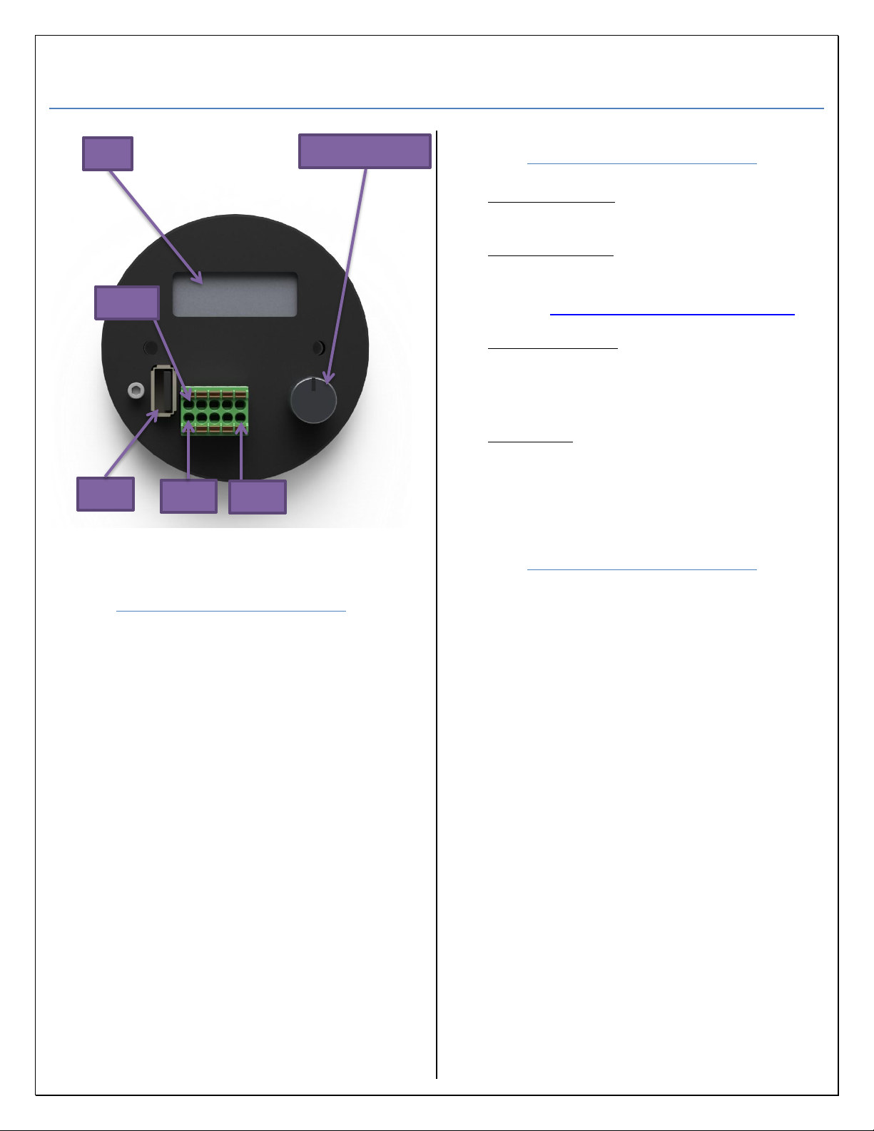
Device Overview
Figure 1: 4057B
4057B Pinout
Pin 1: DC input (12V-30V)
Pin 2: Common (-)
Pin 3: FTC or FTV output
Pin 4: Mag Coil + (VRS)
Pin 5: RF Coil
Pin 6: RF Coil
Pin 7: Mag Coil –(VRS)
Pin 8: Digital Output
Pin 9: Common (-)
Pin 10: Digital Input
DO NOT DISCONNECT POWER FROM
DEVICE WHILE IN LCD SETUP MODE
CONFIGURATION MAY NOT BE SAVED.
PRESSING DOWN ON THE SELECTION
DIAL TO TURN ON THE SCREEN WILL
TAKE YOU TO THE MAIN MENU.
IF THE DISPLAY TURNS OFF WHEN IN
LCD SETUP MODE SETTINGS MAY NOT BE
SAVED. MAKE SURE TO EXIT TO
OVERVIEW SCREENS TO SAVE SETTINGS.
Definitions
LCD Setup Mode: Configuration is done
through the LCD using the selection dial (Figure 1).
USB Setup Mode: Configuring the device is
done by a file that is generated by the “4057 Series
Configuration Software”. (Can be downloaded from
our website. WWW.SPECTECSENSORS.COM)
Overview Screens: Rotating the selection dial
allows the user to view how the device is
configured and view the current condition of the
input and outputs.
Main Menu: This is the root menu for setting up
the device when in LCD setup mode (Figure 2).
LCD User Interface
Overview
Rotate the selection dial to move the cursor (*)
on screen. Rotating clockwise moves the cursor to
the next on-screen option, rotating counter
clockwise moves the cursor to the previous option.
Pressing down on the control dial makes a selection.
Values use a black cursor and can be changed by
using the selection dial. Simply rotate the selection
dial to move the black cursor until it highlights the
value to be changed. Momentarily press down on
the control dial to make the selection. Rotate the
dial clockwise to increase the value and counter
clockwise to decrease the value. Momentarily press
down on the control dial to set the value and allow
the cursor to move to the next option.
If the LCD has turned off (typically after 1
minute of inactivity) simply rotate the selection dial
to turn on the screen. This can also happen when in
LCD Setup Mode and if so, the device will return to
the Overview Screens and the user will need to redo
the device configuration.
Pin 1
Selection Dial
LCD
Pin 10
USB
Pin 5
3
LCD Setup Mode
Entering LCD Setup Mode
1) Apply power to the 4057B.
2) When you see “Push Button to Enter Setup”
momentarily press down on the selection
dial. If you do not see the above message,
rotate the selection dial until you do.
3) Enter password when applicable. See
Password Entry for instructions.
4) The menu in Figure 2 will appear.
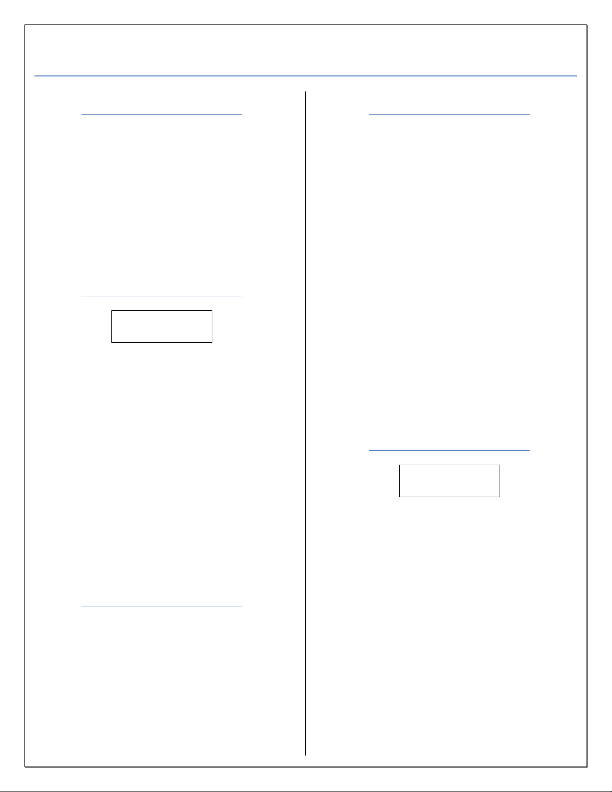
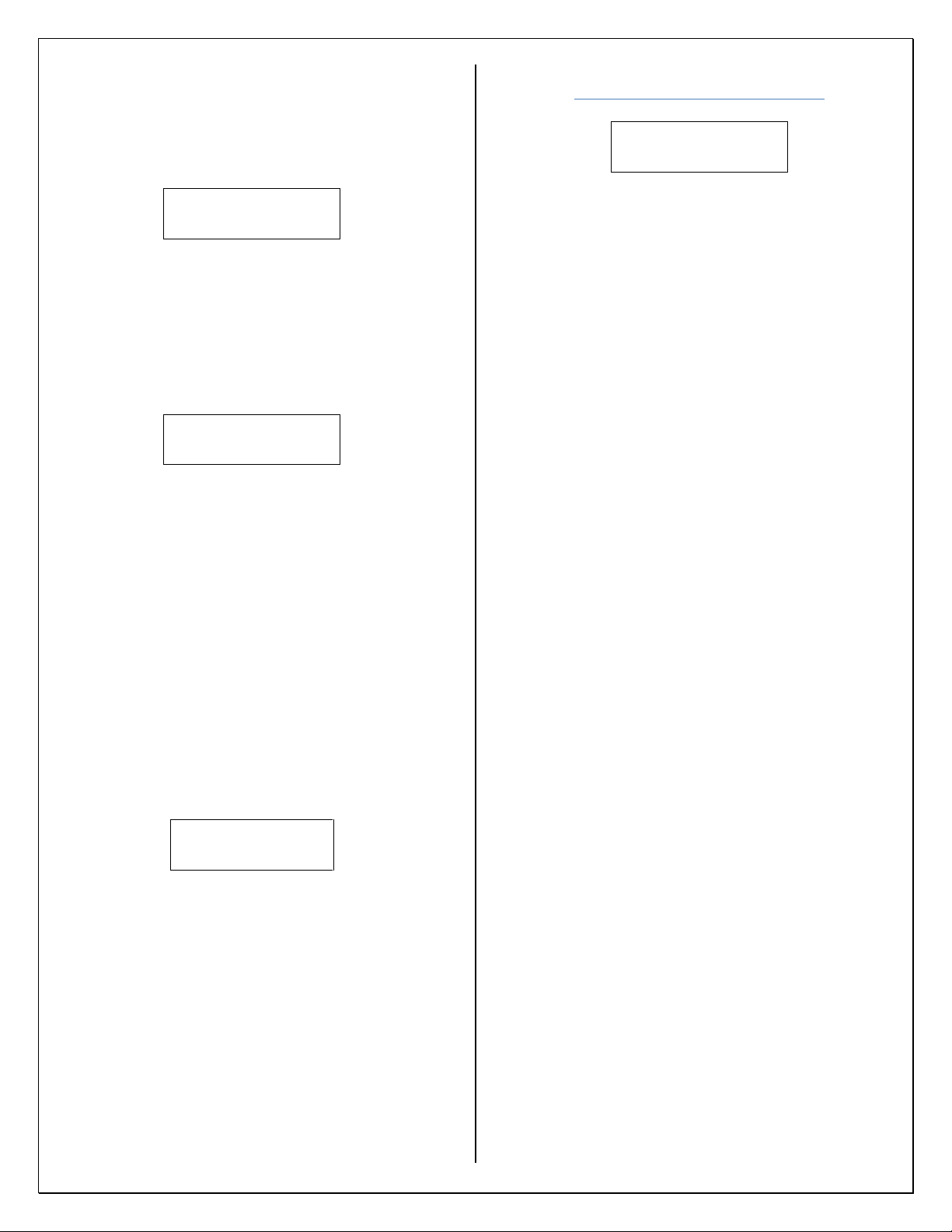
Main Menu
Input* Output
Options Exit
Figure 2: Main Program Menu.
“Input” allows user to select from input
sources: Digital, Mag, or RF see Input Setup.
“Output” configures the Digital and
DAC output pins. see Output Type Setup and
Analog Setup.
“Options” configures the display,
password, date and time, and device reset
see Options Setup.
“Exit” selection exits program mode and
saves configuration settings see Exiting LCD
Setup Mode.
Exiting LCD Setup Mode
1) Return to the Main menu (Figure 2).
2) Rotate the selection dial until the cursor
moves to the “Exit” option.
3) Momentarily press down on the selection
dial to exit.
4) All settings are saved.
Password Entry
1) When enabled you will be prompted for a
password (Figure 11) when entering LCD
setup mode. You will start at the first digit
automatically.
2) Rotate the dial until the value you want is
displayed.
3) Momentarily press down on the selection
dial to set the value.
4) You will be taken automatically to the next
digit. Repeat steps 2 and 3 until all four
digits are set.
5) After setting the fourth digit you can rotate
the selection dial and choose from or .
will take you to the main menu if the
password is correct (Figure 2) or will
clear the password allowing you to re-enter
the password if you made a mistake. See
Options Setup for instructions on setting up a
password.
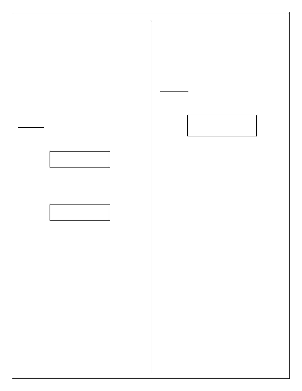
Input Setup
Mag* RF
Digital
Figure 3: Input Menu.
1) Move cursor next to desired input.
2) Momentarily press down on selection dial.
3) After selection is made you will be returned
to main menu (Figure 2).
“Digital” enables the digital input
(default).
“Mag” enables the magnetic pickup
input (VRS).
“RF” enables the RF input (RF4 or
RF10 depending on model).
ALL INPUT OPTIONS ARE DISPLAYED
EVEN IF MODEL PURCHASED DOES NOT
HAVE THAT INPUT OPTION AVALIABLE.

4
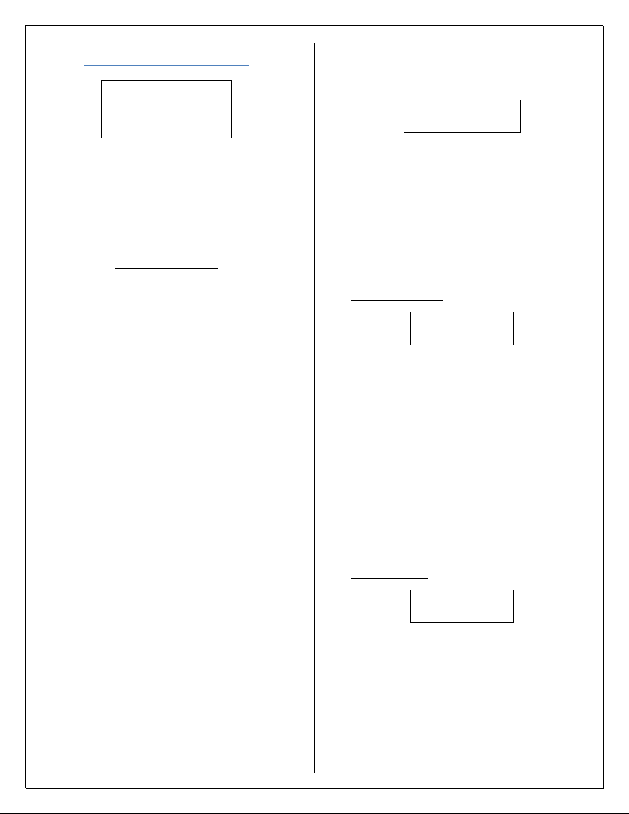
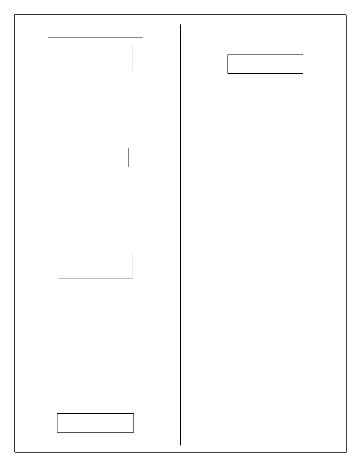
Options Setup
Factory Display*
Reset
Password Date/Time
Figure 4: Options Menu.
“Factory Reset” sets the unit back to
factory defaults including the password.
“Display” allows the user to change the
timer for the backlite and display (Figure 7).
“Password” allows user to set up a 4-
digit numeric password. When entering the
main menu (Figure 2) the user will be
prompted for the password. Overview
screens can still be viewed without entering
the password.
“Date/Time” sets date and time (24-
hour format).
Factory Reset:
1) After selecting factory reset you will see the
following screen.
Default Settings
yes no*
Figure 5: Factory Reset.
2) Selecting yes will take you to the following
screen and no will take you to the main
menu (Figure 2).
Confirm Reset
yes no*
Figure 6: Confirm Reset.
3) You will be prompted to confirm your
choice. Yes will reset the device to factory
defaults and no will take you to the main
menu (Figure 2) and will not affect any
settings.
Display:
BackLite
LCD time*
Figure 7: Display Options.
BackLite Setup:
After selecting BackLite you will see Figure
8. You can set the timer from 000 to 255.
000 will permanently turn the backlight off
and 255 will permanently turn it on. Values
001-254 will cause the back light to turn off
after set time of inactivity. If a value >255 is
entered the device will default to 255.
Factory default is for 30 seconds.
Backlight Timer
030 sec
Figure 8: BackLite.
1) To set up the timer select the appropriate
digit by rotating the selection dial to
highlight the digit you want to change.
2) Momentarily press down on the selection
dial.
3) Rotate the dial until the digit changes to the
desired value then momentarily press down
on the selection dial again to set the value.
4) Repeat steps 2-4 to set up the remaining
digits.
5) After entering the value move the cursor to
and momentarily press down on the
selection dial. This will take you back to the
main menu (Figure 2).
LCD Timer Setup:
After selecting LCD time, you will see
Figure 9. You can set the timer from 010 to
255. The minimum time that can be set is
010. Setting it to 255 will permanently turn
on the display. The values 010-254 will
cause the LCD to turn off after set time of
inactivity. The LCD timer cannot be set
<010, if it is it will default to 010. If a value
of >255 is entered the device will default to
255. Factory default is set for 60 seconds.
LCD Timer
060 sec
Figure 9: LCD Timer.
5
1) To set up the timer select the appropriate
digit by rotating the selection dial and
highlighting the digit you want to change.
2) Momentarily press down on the selection
dial.
3) Rotate the dial until the digit changes to the
desired value then momentarily press down
on the selection dial again to set the value.
4) Repeat steps 2-4 to set up the remaining
digits.
5) After entering the value move the cursor to
and momentarily press down on the
selection dial. This will take you back to the
main menu (Figure 2).
Password:
1) After selecting password, the following
screen will be displayed (Figure 10).
Password Enable
yes no
Figure 10: Password Enable.
2) Selecting yes will take you to password
entry (Figure 11). No will take you back to
main menu (Figure 2).
Password
____
Figure 11: Password Entry.
3) You will be taken to the first digit
automatically. Rotate the dial until the value
you want is displayed.
4) Momentarily press down on the selection
dial to set the value.
5) You will be taken automatically to the next
digit.
6) Repeat steps 3 and 4 until all four digits are
set.
7) After setting the fourth digit you can rotate
the selection dial and choose from or .
will set the password and take you back
to the main menu (Figure 2) or will reset
the password and will allow you to re-enter
the password if you made a mistake or want
to change it. Momentarily press down on the
selection dial to choose.
8) If you need to disable the password return to
Password Enable (Figure 10) and choose no.
This will remove and disable the password.
DO NOT FORGET TO RECORD YOUR
PASSWORD IN A SECURE LOCATION. IF
YOU LOSE YOUR PASSWORD THE DEVICE
WILL HAVE TO BE SENT BACK TO THE
FACTORY TO BE RESET AND ALL
SETTINGS WILL BE LOST.
A FACTORY RESET WILL DISABLE THE
PASSWORD.
Date/Time:
1) After selecting Date/Time, the following
screen will be displayed (Figure 12).
Enter Date MDY/Time 24
Date: 01/30/18
Time: 23:59:59
Figure 12: Date & Time Entry.
2) To set the date and time select the
appropriate digit by rotating the selection
dial and highlighting the digit you want to
change.
3) Momentarily press down on the selection
dial.
4) Rotate the dial until the digit changes to the
desired value then momentarily press down
on the selection dial again to set the value.
5) Repeat steps 2-4 to set up the remaining
digits.
6) After entering the value move the cursor to
or and momentarily press down on the
selection dial. Both will set the date/time
and take you back to the main menu (Figure
2).
THERE IS NO BATTERY BACKUP, IF THE
UNIT IS UNPLUGGED OR LOOSES POWER
THE DATE AND TIME WILL BE RESET.
6
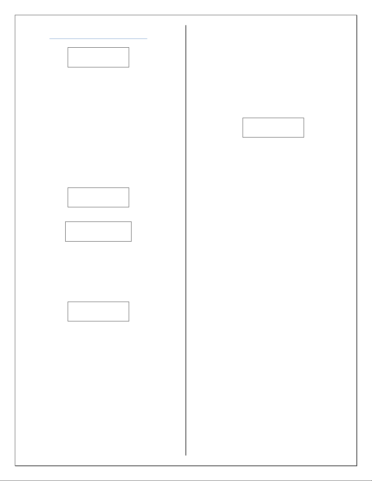
Output Type Setup
Hz rpm gpm
BPH LPM LPH
fps Mph m/s kph
K factor
Figure 13: Output Type Menu.
These options can be broken down into
three categories: Hz, EU, and K-factor.
1) “Hz” This option gives the ability to set up a
digital output with a multiplier or divider
functionality and an analog output. Selecting
this option will display Figure 14.
Back*
Analog Digital
Figure 14: Output Setup.
“Back” Returns you to the Main Menu
when finished setting up outputs. (Figure 2)
“Analog” Configuration settings for the
DAC output. See Analog Setup.
“Digital” Configuration settings for the
digital output. See Digital Output Setup (Hz
Selection only).
2) “EU”= (rpm, gpm, BPH, LPM, LPH, fps,
Mph, m/s, kph) these options allow the user
to set up a conversion that gives an output
based on a target count. These units will be
referred to as EU (engineering units) for the
rest of this document. See EU Setup.
Abbreviation definitions for EU:
rpm = Revolutions per minute
gpm = Gallons per minute
BPH = Barrels per hour
LPM = Liters per minute
LPH = Liters per hour
fps = Feet per second
Mph = Miles per hour
m/s = Meters per second
kph = Kilometers per hour
3) “K-factor” The user can set up a linear
scaler with 2-16 points. See K-factor Setup.
Digital Output Setup
(Hz Selection only)
Multiply* Disable
Divide
Figure 15: Digital Output (Hz).
“Multiply” Increase the number of input
targets.
“Divide” Decrease the number of input
targets. This option also allows for a custom
duty cycle and an invert output option.
“Disable” No digital output when this
option is selected.
Multiplier Setup:
Multiply by
000001.000
Figure 16: Multiply Selection.
1) “000001.000” To set up a multiplier value
select the appropriate digit by rotating the
selection dial and highlighting the digit you
want to change.
2) Momentarily press down on the selection
dial.
3) Rotate the dial until the digit changes to the
desired value.
4) Momentarily press down on the selection
dial to set value.
5) Repeat steps 2-4 to set up remaining digits.
6) When done select “” to return to output
setup (Figure 14).
Divider Setup:
Divide by
000001.000
Figure 17: Divide Selection.
1) “000001.000” To set up a divider value
select the appropriate digit by rotating the
selection dial and highlighting the digit you
want to change.
2) Momentarily press down on the selection
dial.
3) Rotate the dial until the digit changes to the
desired value.
7
4) Momentarily press down on the selection
dial to set the digit.
5) Repeat steps 2-4 to set up remaining digits.
6) When done select “” to move to next step.
(Figure 18).
Custom Duty Cycle
Yes No
Figure 18: Custom Duty Cycle.
“Yes” Allows for a custom duty
cycle (see Figure 19).
“No” No custom duty cycle, defaults
to 50%. The user will then be taken to
the invert option (see Figure 20).
Custom Duty Cycle
50%
Figure 19: Custom Duty Cycle Setup.
1) To set up a custom duty cycle, select one of
the two digits by rotating the selection dial
and highlighting the digit you want to
change.
2) Momentarily press down on the selection
dial.
3) Rotate the dial to change to desired value.
4) Momentarily press down on the selection
dial to set the digit.
5) Repeat steps 2-4 if change is needed for the
other digit.
6) When done select and momentarily press
down on the selection dial to take you to the
invert output option (Figure 20).
Invert Output
Yes* No
Figure 20: Invert Output Setup.
This option allows you to invert the
output when compared to the input. After
selecting yes or no you will be taken back to
the output setup screen (Figure 14). If a
divider is being used it may not be
detectable that the output is inverted.
EU Setup
Pulses per unit time:
000001→
Figure 21: Target Count.
1) After selecting one of the EUs you will be
prompted for “Pulses per unit time”. This is
the number of pulses needed to equal 1EU.
(Figure 21)
a. Example: If you want a pulse for
every revolution for a 60-tooth gear
you would select rpm (Figure 13)
and enter 60 into the screen above.
This would result in a pulse for every
revolution per minute and display the
current rpm on the overview screens.
The DAC output is converted as
well.
2) To set up a value, select the appropriate digit
by rotating the selection dial and
highlighting the digit you want to change.
3) Momentarily press down on the selection
dial.
4) Rotate the dial until the digit changes to the
desired value.
5) Momentarily press down on the selection
dial to set the digit.
6) Repeat steps 2-5 to set up the remaining
digits.
7) After entering the value move the cursor to
the arrow and momentarily press down on
the selection dial.
8) You will be taken back to the output setup
(Figure 14).
8
K-factor Setup
Gpm BPH LPM
LPH GPH m^3/h
m^3/min cfm ft^3/h
Figure 22: Unit Selection.
1) Select needed unit of measure to be
displayed.
2) Set the number of K-factors needed by
rotating the dial and highlighting the two-
digit number you see in Figure 23. The
minimum number of K-factors you can have
is 2 and the maximum is 16.
Number of Kfactors
02
Figure 23: Number of K-factor Entry.
3) Momentarily press down on the selection
dial to set the value.
4) Use selection dial to move to the next step in
setup by selecting and pressing down on
the selection dial.
5) The next screen will prompt you for the
frequency range and the K-factor value for
that range.
Enter Freq/Kfactor # 1
Freq: 00000.000
kFac: 00000.000
Figure 24: Freq\K-factor Entry.
6) To enter the values, rotate the selection dial
to select the appropriate digit.
7) Momentarily press down on the selection
dial.
8) Rotate the selection dial to change the value.
9) Momentarily press down on the selection
dial to set the digit. Then rotate the dial to
the next digit that needs adjusted.
10)The arrows in the lower right and left
corners are used to navigate to the next ()
or previous () Freq. and K-factor.
11)After all the values have been entered you
will be prompted to enable or disable the
digital output (Figure 25).
Digital Output Enable*
Disable
Figure 25: Digital Output
12)After choosing to enable or disable the
digital output you will be prompted to
enable or disable the analog output.
DAC Output Enable*
Disable
Figure 26: Analog Output
13)If you select Enable, see Analog Setup for
instructions on how to set up the DAC.
Selecting Disable will take you back to the
main menu (Figure 2).
Abbreviation definitions for K-factor:
Gpm = Gallons per minute
BPH = Barrels per hour
LPM = Liters per minute
LPH = Liters per hour
GPH = Gallons per hour
m^3/h = Cubic meters per hour
m^3/min = Cubic meters per minute
cfm = Cubic feet per minute
ft^3/h = Cubic feet per hour
9
Analog Setup
FTV FTC*
Disable Back
Figure 27: Analog Menu.
“FTV” Frequency to voltage setup.
“FTC” Frequency to current setup.
“Disable” Disables the analog output.
“Back” Takes you back to output setup
(Figure 14).
1) Use the selection dial to choose FTV or
FTC. After making your selection press
down on the selection dial. You will see one
of the following screens.
0-5V 0-10V*
Back
Figure 28: FTV Range Selection.
4-20mA 0-20mA*
0-24mA Back
Figure 29: FTC Range Selection.
“Back” Returns you to the analog menu
(Figure 27).
2) After choosing the output type and range
you will see the following (Figure 30).
Minimum __
000000.000
Figure 30: FTV/FTC Minimum.
“___” Hz or the EU that was selected
will be displayed here.
IF THIS IS BEING SETUP FOR AN EU ALL
ENTERED VALUES MUST BE IN THAT EU
FORMAT. EXAMPLE: IF YOU HAVE
SELECTED RPM AND YOUR MINIMUM
VALUE IS 32 RPM THE ENTERED
MINIMUM SHOULD LOOK LIKE 000032.00.
3) To set up your minimum value select the
appropriate digit by rotating the selection
dial and highlighting the digit you want to
change.
4) Momentarily press down on the selection
dial.
5) Rotate the selection dial until the digit
changes to the desired digit.
6) Momentarily press down on the selection
dial again to set the value.
7) Repeat steps 3-6 to set up the remaining
digits.
8) After setting up the min range selecting
will take you to max entry (Figure 31).
Maximum __
100000.000
Figure 31: FTV/FTC Maximum.
“___” Hz or the EU that was selected
will be displayed here.
9) To set up your maximum value select the
appropriate digit by rotating the selection
dial and highlighting the digit you want to
change.
10)Momentarily press down on the selection
dial.
11)Rotate the dial until the digit changes to the
desired value.
12)Momentarily press down on the selection
dial to set the value.
13)Repeat steps 9-12 to set up remaining digits.
14)After setting up the max range selecting
will take you back to output setup (Figure
14).

10
Updating Firmware
USER CONFIGURATION WILL BE RESET
(INCLUDING PASSWORD) AND THE
DEVICE WILL NEED TO BE
RECONFIGURED UPON COMPLETION OF
A FIRMWARE UPDATE.
DO NOT POWER DOWN DEVICE DURING
FIRMWARE UPDATE.
If needed contact factory for latest
firmware. It may be available on our website
for download. If the files are zipped extract
them before copying them onto a USB
thumb drive.
1) Copy files onto the root directory of a USB
thumb drive (it is recommended to use a
blank USB thumb drive).
2) Power down the 4057B.
3) Insert thumb drive containing update.
4) Press and hold down the selection dial.
5) Power up the device.
6) Release selection dial once update has
started.
7) After updating is complete the 4057B will
start up in the updated application.
8) Power down the device and remove thumb
drive.
9) Power up device and reconfigure.
10)Verification of update can be done by
checking firmware version under “Push
Button to Enter Setup” in the overview
screens.

11
USB SETUP MODE
Figure 1B: 4057 Series Configuration Software
USB User Interface
Overview
Configuration of the 4057 can be done through
the USB port by using the 4057 Series
Configuration Software. Using this simple user
interface allows quick set up times and batch
programming of devices that have the same
parameters.
Installation Instructions
1) Download install file from the product page
at WWW.SPECTECSENSORS.COM
2) Open file from saved location.
3) Double click on file to install.
4) You will be prompted to agree to the EULA.
5) The next window will prompt you for a
desktop shortcut.
6) On the final window click install to finish.
THE PASSWORD CANNOT BE SET UP
FROM THE CONFIGURATION SOFTWARE.
IT MUST BE DONE THROUGH THE LCD
SETUP MODE.
Menu Bar
Figure 2B: File
“File” Here you will find Open Config,
Save As, and Load Defaults.
“Open Config”You can open and edit a
previously saved configuration file.
“Save As”Here you can save the
configuration and then transfer the file to a
USB thumb drive to program the 4057. (See
Loading Configuration)
“Load Defaults”Resets all the options
in the configuration software back to factory
defaults.
Figure 3B: Help
“Help” gives access to this user manual
and information about the developer.
WHEN SAVING THE CONFIGURATION,
YOU CAN NAME IT ANYTHING YOU WANT
BUT WHEN YOU PROGRAM THE 4057 THE
FILE MUST USE THE FOLLOWING NAME
AND FILE EXTENSION FOR THE 4057 TO
RECOGNIZE THE FILE: in_cfg.csv

12
Mode Setup
Figure 4B: Mode Selection
“Scalar" Enables set up of multiplier,
divider, DAC, and engineering units.
“K-factor” Enables set up of 2-16 point
linear K-factor.
Input Source Setup
Figure 5B: Input Source
“Digital” Enables the digital input
(default).
“Mag (VRS) Sensor” Enables the
magnetic pickup input (VRS).
“RF Sensor” Enables the RF input (RF4
or RF10 depending on model).
Unit Selection Setup
Figure 6B: EU
Here you can select Hz or an EU
(Engineering Unit). If an EU is selected you
will need to fill in the target count. This is
the number of pulses needed to equal 1 EU.
See Output Type Setup in the LCD setup
section for definition of EU.
Example: If you want a pulse for every
revolution for a 60-tooth gear you would
select rpm from the drop down and enter 60
into the target count field. This would result
in a pulse for every revolution. The DAC
output is converted as well.
DAC Output Setup
Figure 7B: DAC Output
Options for the analog output are located
here.
IF THIS IS BEING SET UP FOR AN EU ALL
ENTERED VALUES MUST BE IN THAT EU
FORMAT. EXAMPLE: IF YOU HAVE
SELECTED RPM AND YOUR MINIMUM
VALUE IS 32 RPM THE ENTERED
MINIMUM SHOULD LOOK LIKE 32.0

13
Digital Output Setup
Figure 8B: Digital Output
“Multiply” Select this option to increase
the number of input targets.
“Divide” Select this option to decrease
the number of input targets. This option also
allows for a custom duty cycle and an invert
output option.
“Disable” There is no digital output
when this option is selected.
The above options are only available for
the scalar mode (Figure 4B) and Hz unit
(Figure 6B).
Duty Cycle Setup
Figure 9B: Duty Cycle
A custom duty cycle is only available for
a scalar setup with the divider function
enabled.
“Automatic” selection keeps the digital
output at a 50% duty cycle.
“Manual” selection allows the user to
set up a custom duty cycle for the digital
output.
Invert Output Setup
Figure 10B: Invert Output
Checking this box will invert the digital
output when compared to the input.
The invert option is only available for a
scalar setup with the divider function
enabled. If a divider is being used it may not
be detectable that the output is inverted.
K-factor Setup
Figure 11B: K-factor
“Num points” Changing this value
determines the number of K-factors to be
entered. You can have 2-16 K-factor points.
“Unit” assigns a unit of measure to the
K-factor that will be displayed on the LCD.
“Freq/Range” Enter the range for the
corresponding K-factor in this field.
“K-Factor” Enter the K-factor for the
corresponding frequency/range in this field.
14
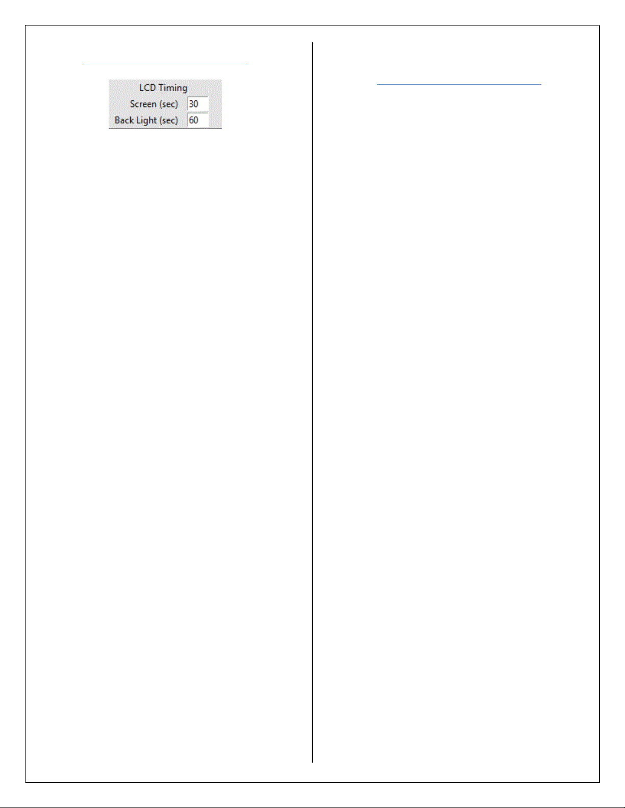
Display Settings Setup
Figure 12B: Display Settings
“Screen” controls the display. You can
set this timer from 010 to 255. The
minimum time that can be set is 010. Setting
it to 255 will permanently turn on the
display. The values 010-254 will cause the
display to turn off after set time of
inactivity. The timer cannot be set to <010,
if it is it will default to 010. If a value of
>255 is entered the device will default to
255.
“Back Light” controls the light. You
can set this timer from 000 to 255. The value
000 will permanently turn the light off and
255 will permanently turn it on. Values 001-
254 will cause the back light to turn off after
set time of inactivity. If a value of >255 is
entered the device will default to 255.
Loading Configuration
Onto 4057B
1) Copy in_cfg.csv that was created with the
configuration software onto the root
directory of a blank USB thumb drive.
2) Apply power to the 4057B and wait until the
device has booted.
3) Make sure the device is not in program
mode but in overview screens.
4) Plug the thumb drive into the USB port on
the 4057B.
5) If the 4057B is password protected you will
be prompted to enter the password before
the unit allows you to program it (See
Password Entry).
6) After a few seconds the device is ready.
Scroll through the overview screens to
verify your configuration has been applied.
7) Remove the USB thumb drive.
8) Power cycle the device.
WHEN LOADING THE CONFIGURATION
ONTO THE 4057B THE FILE MUST USE THE
FOLLOWING NAME AND FILE EXTENSION
FOR THE 4057 TO RECOGNIZE THE FILE:
in_cfg.csv
A FILE WILL BE GENERATED ON THE USB
(output_cfg.csv). THIS FILE CAN BE USED TO
CONFIRM CONFIGURTAION OF THE
DEVICE OR CAN BE SENT TO SPECTEC
FOR EVALUTAION IF AN ISSUE OCCURS.
Table of contents
Other Spectec Industrial Equipment manuals

Popular Industrial Equipment manuals by other brands


HYDAC FILTER SYSTEMS
HYDAC FILTER SYSTEMS LVU-CD-10 Operating and maintenance instructions

resideo
resideo Braukmann Installation and operating manual

ABB
ABB TPS52 Series Operation manual

Afag
Afag GE-25-P Assembly and operating instructions

PKP
PKP DV04 Series instruction manual

Rottler
Rottler SG8 Operation and maintenance manual