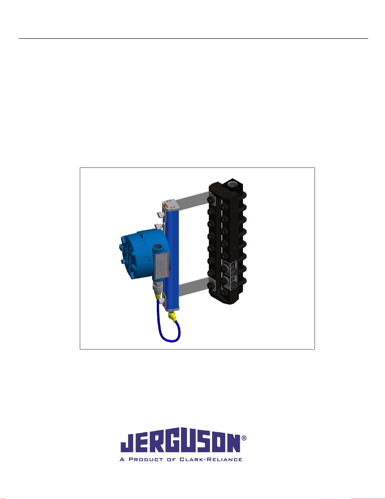
Jerguson LUMASTAR EPL-100 Guide

TM
®
Installation, Operation, & Maintenance Instructions
IOM J500.32
6/1/2021
Jerguson LumaStar
(EPL-100, EPL-316, & 24VDC Options)

IOM J500.32
Jerguson®LumaStar™2021.05
2
16633 Foltz Parkway ● Strongsville, OH 44149 USA ● Telephone: +1 (440) 572-1500 ● Fax: +1 (440) 238-8828
www.clark-reliance.com ● sales@clark-reliance.com
Table of Contents
1. INTRODUCTION……………………………………………………………………..3
2. WARRANTY………………………………………………………………………….3
3. ABOUT THIS MANUAL……………………………………………………………..3
4. INSPECTION & DELIVERY………………………………………………………...3
5. PRODUCT DESCRIPTION…………………………………………………………3
6. 115 / 230 VAC Models EPL-100 & EPL-316…………………………………..4-9
6.1 SPECIFICATIONS…………………………………………………………………………………4-5
6.2 COMPONENTS……………………………………………………………………………………....5
6.3 INSTALLATION WIRING…………………………………………………………………………5-6
6.4 MAINTENANCE……………………………………………………………………………………6-7
6.5 TROUBLESHOOTING………………………………………………………………………….......8
6.6 LABELS……………………………………………………………………………………………….9
7. BARRIER DRIVEN 24VDC Models EPL-100 & EPL-316…………………10-15
7.1 SPECIFICATIONS………………………………………………………………………………….10
7.2 COMPONENTS……………………………………………………………………………………..11
7.3 INSTALLATION WIRING……………………………………………………………………...11-14
7.4 TROUBLESHOOTING……………………………………………………………………………..15
8. BRACKET INSTALLATION (ALL MODELS)……………………………….16-20
8.1 UNIVERSAL BRACKET……………………………………………………………………….16-18
8.2 ALTERNATE BRACKET………………………………………………………………………….19
8.3 REFLEX GAGE BRACKET……………………………………………………………………….20
9. SPARE PARTS (ALL MODELS)………………………………………………....21

IOM J500.32
Jerguson®LumaStar™2021.05
3
16633 Foltz Parkway ● Strongsville, OH 44149 USA ● Telephone: +1 (440) 572-1500 ● Fax: +1 (440) 238-8828
www.clark-reliance.com ● sales@clark-reliance.com
1.Introduction
Clark-Reliance®is a global leader in the level indication and control, sight-flow indication, and filtration and
separation industries. We are dedicated to offering the largest and broadest range of instrumentation products
and being the single source for every type of level measurement and control to meet the varying demands of the
process industry.
Jerguson Gage and Valve, a leading supplier of level gaging products, offers the world’s largest selection of liquid
level glass gages, magnetic level gages, liquid level switches and level transmitters. Since 1905, Jerguson gages
and valves have been installed in a wide variety of liquid level applications, from basic chemical storage tanks to
the most advanced nuclear aircraft carriers. With complete product offerings in both traditional glass gages and
magnetic gages, Jerguson meets a diverse set of customer needs.
2. Warranty
Clark-Reliance warranties its manufactured goods as being free from defects in material and workmanship for one
(1) year from the date of shipment. If any of the goods are found by the seller to be defective, such goods will be
replaced or repaired at the seller's cost. Refer to the Clark-Reliance Terms & Conditions for full warranty details.
3. About This Manual
This manual is designed to aid and guide in the installation, operation, and maintenance of the Lumastar family of
illuminators. Authorized personnel must read and understand all instructions before attempting to install, operate
or maintain this equipment. Only persons certified to perform work described herein should attempt any actions
suggested. Safety precautions and company safety standards should always be observed when performing the
activities described in this manual.
4. Inspection & Delivery
Upon receiving the LumaStar, check all components carefully for damage incurred during shipping. Sign for the
shipment noting “damaged” and immediately notify the shipping firm of any such damage and request damage
inspection. Confirm illuminator model number (on nameplate), power requirements, and hazardous area
approvals meet the application specifications. Unit should be stored in an area protected from the elements and
corrosive fumes, in a secure manner where they can neither fall, nor be struck by other objects. Care should be
taken to protect the window and the end connections from damage.
5. Product Description
The Jerguson LumaStar family of products are constructed to the highest of standards. Equipped on a Jerguson
armored glass gage, this product can greatly enhance visibility of the liquid level contained within. These products
are designed to be maintenance free for an estimated service life of 100,000 hours of continuous use. The power
supply enclosures are explosion proof, and the lighting circuit is intrinsically safe. A single power supply can cover
up to a 4-section size 9 gage (~58’’ of visible range).
These illuminators must be installed, operated, and maintained with reasonable care and due regard for the
applications and environment if they are to provide reliability for their service lifetime.
IOM J500.32
Jerguson®LumaStar™2021.05
4
16633 Foltz Parkway ● Strongsville, OH 44149 USA ● Telephone: +1 (440) 572-1500 ● Fax: +1 (440) 238-8828
www.clark-reliance.com ● sales@clark-reliance.com
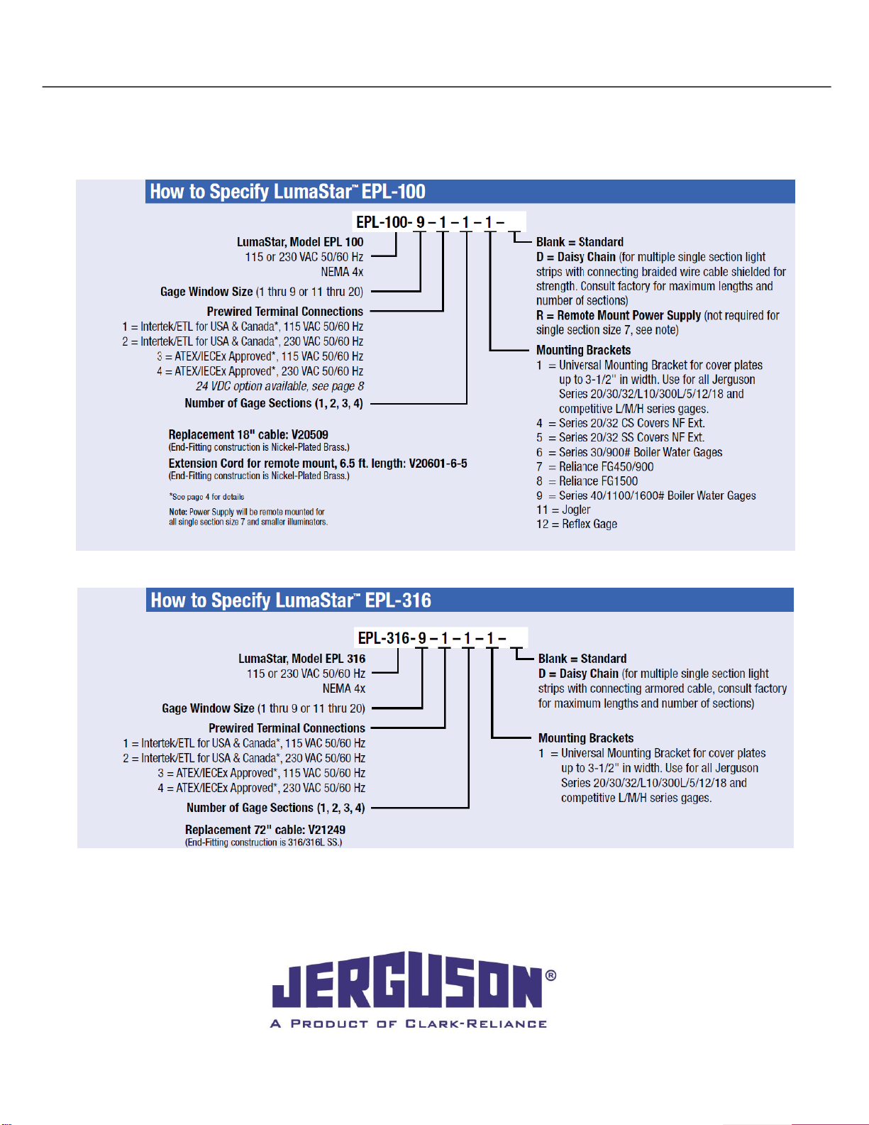
6. 115 / 230 VAC Models EPL-100 & EPL-316
6.1 Specifications
Note: Power Supply is remote mount for all sizes on EPL-316

IOM J500.32
Jerguson®LumaStar™2021.05
5
16633 Foltz Parkway ● Strongsville, OH 44149 USA ● Telephone: +1 (440) 572-1500 ● Fax: +1 (440) 238-8828
www.clark-reliance.com ● sales@clark-reliance.com
6.2 Components
There are three main components that make up the LED illuminator: the light strip, the power supply, and the cord
connecting these two main pieces. The cord may have more than one piece depending on the required distance
between the illuminator and the power supply. The power supply is constructed of aluminum or stainless steel, a
conduit sealing device and a stainless steel I.S. connector. The light bar is constructed of aluminum or stainless
steel, glass and silicone. Questions regarding acceptable applications should be directed to The Clark-Reliance®
Corporation.
6.3 Installation Wiring
CAUTION: All lights are tagged with the service conditions for that particular unit. These specifications
are located on the Jerguson tag on the power supply housing and are contained in the “Specifications”
section of this manual. Do not use or refer to specifications listed on red label on the power supply
housing. They are specifications for generic use. Review the ratings prior to installation and again prior
to start-up, to ensure proper operation in the installed environment. Should there be any doubt as to the
applicability of a unit for the installed environment, consult the factory before placing the unit into
service.
All installation steps should be performed by a qualified technician and should be executed in accordance with all
applicable national and local codes.
The light and power supply should be checked to ensure that they contain no foreign matter, and that the end
connections are clean, undamaged, and in line with existing conduit.

IOM J500.32
Jerguson®LumaStar™2021.05
6
16633 Foltz Parkway ● Strongsville, OH 44149 USA ● Telephone: +1 (440) 572-1500 ● Fax: +1 (440) 238-8828
www.clark-reliance.com ● sales@clark-reliance.com
Step by step instructions:
See Drawing CI-26677 for safety information for hazardous locations.
CAUTION: Before working with the power supply, verify that the area is free of flammables and the AC
power circuit is off.
1. Loosen cover locking screw and open the cover of the power supply housing. Insert the AC Line wires into
the housing and connect to the “AC IN” terminal block. Ground screws are located both inside and outside
the enclosure.
CAUTION:The DC output is pre-wired. If this connection is removed during installation, reconnect the
“AC IN” and “DC OUT” to the proper positions. Failure to do so will result in permanent damage to the
power supply.
2. If the cord will not reach the power supply, contact your local representative for the required extension cable.
3. Replace the cover on the power supply housing.
4. Switch “ON” the power supply making sure the Illuminator is functioning properly, with all LEDs illuminated.
5. If the LED’s do not illuminate, remove the cover on the power supply once the power has been turned on. A
red power indicating LED will be lit if it is wired correctly. See Figure 1.
6. If the LED in the power supply is not lit, check the power source and the connections before continuing. See
Section 6.5 Troubleshooting
The LED illuminator can run continuously. The operating life of LED lights can exceed 100,000 hours under
normal conditions.
6.4 Maintenance
Fuse Replacement
This power supply is fused for AC protection. In the event of a large voltage surge, the fuse may release,
causing no output voltage. Replace fuse, referring to Clark-Reliance part # E-F-DIN-0250 T
1. Loosen cover locking screw and open the cover of the power supply housing.
2. Remove and replace bad fuse. Refer to Figure 1 for fuse location.
Replacing Power Supply
1. Loosen cover locking screw and open the cover of the power supply housing. Disconnect AC power in and
remove AC wires from enclosure.
2. Remove assembly from gage and relocate to desired work area.
3. Disconnect power cord between power supply and light bar assembly.
4. Trim gasket material at top end cap to match slot opening and slide out bracket and mounting hardware.
5. Loosen power supply screws and slide power supply off light bar assembly.
6. Slide new power supply onto light bar assembly.
7. Insert bracket and mounting hardware for top bracket back into slot.
8. Securely tighten the power supply screws and the top bracket screw.
9. Install power cord between power supply and light strip making sure connectors are fully connected.
IOM J500.32
Jerguson®LumaStar™2021.05
7
16633 Foltz Parkway ● Strongsville, OH 44149 USA ● Telephone: +1 (440) 572-1500 ● Fax: +1 (440) 238-8828
www.clark-reliance.com ● sales@clark-reliance.com
Routine Inspection
Keep window on the front of the light clean using a clean damp cloth. Avoid using chemical cleaners that may
damage the silicone seals. If cleaner is required, do not spray directly onto the light. Apply a small amount to the
rag and carefully wipe the glass only. Never use harsh abrasives, wire brushes, metal scrapers, or any material
that could scratch the window. The window may be cleaned while the unit is in operation.
The light may be removed while the unit is in operation during inspection or maintenance of the customer’s gage
glass. The Illuminator may also be disconnected from the power supply, if desired. Disconnect the cord at the
supplied screw connector adjacent to the power supply. The plant power going to the power supply does not
need to be disconnected.
CAUTION: Incorrectly connecting the AC Input to the DC Output will caused permanent damage to the
power supply and possibly create the ignition of hazardous atmospheres.
WARNING: Substitution of components may impair intrinsic safety.
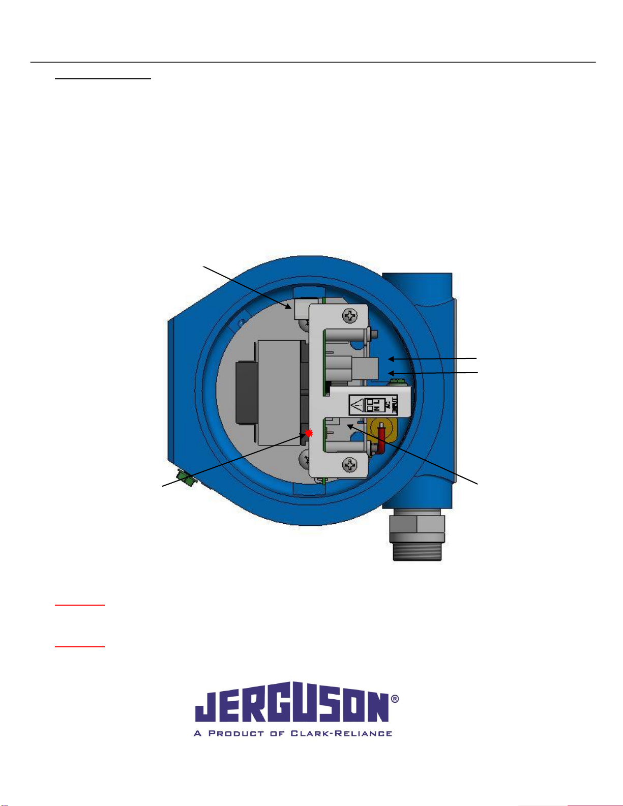
Fuse
Power Indicating
LED
AC Neutral
Pre-wired DC
Output
AC Line
Associated Equipment [Exia]
Figure 1

IOM J500.32
Jerguson®LumaStar™2021.05
8
16633 Foltz Parkway ● Strongsville, OH 44149 USA ● Telephone: +1 (440) 572-1500 ● Fax: +1 (440) 238-8828
www.clark-reliance.com ● sales@clark-reliance.com
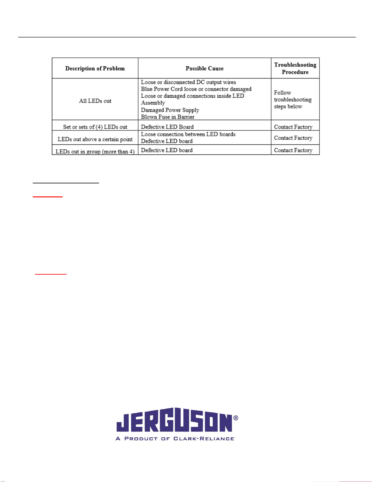
6.5 Troubleshooting
Troubleshooting Steps
CAUTION: Some of these troubleshooting steps are performed with live voltage applied. The assembly
should be moved to a safe area before beginning work. A qualified and properly trained technician must
perform these steps.
1. Remove enclosure cover and look to see if red LED power indictor is on. If red LED is on, go to step 4.
2. Check AC wiring to make sure it is properly installed and tightened in connector.
3. Using a meter, verify AC line voltage at AC connector.
4. Disconnect AC power. Using a small pair of needle-nose pliers, gently remove fuse from holder.
5. Check fuse for continuity with an Ohm meter. If there is continuity, re-install fuse. If there is no continuity,
replace fuse.
6. Check DC output wiring to make sure it is properly installed and tightened.
7. Reconnect AC power.
8. Using a voltmeter set to DC; measure the voltage across the output connector. Voltage should be
between 9VDC and 15VDC.
9. Unscrew and remove blue power cord. Inspect the 4 pins inside end connector to make sure they are
straight and undamaged. If pins are bent, use a small pair of needle-nose pliers to straighten bent pins.
If pins are missing, contact factory.
10. Reconnect power cord making sure connectors are fully seated and tightened.
11. If all steps above check OK, contact factory for support.

IOM J500.32
Jerguson®LumaStar™2021.05
9
16633 Foltz Parkway ● Strongsville, OH 44149 USA ● Telephone: +1 (440) 572-1500 ● Fax: +1 (440) 238-8828
www.clark-reliance.com ● sales@clark-reliance.com
6.6 Labels

IOM J500.32
Jerguson®LumaStar™2021.05
10
16633 Foltz Parkway ● Strongsville, OH 44149 USA ● Telephone: +1 (440) 572-1500 ● Fax: +1 (440) 238-8828
www.clark-reliance.com ● sales@clark-reliance.com
7. Barrier Driven 24VDC Models EPL-100 & EPL-316
7.1 Specifications
IOM J500.32
Jerguson®LumaStar™2021.05
11
16633 Foltz Parkway ● Strongsville, OH 44149 USA ● Telephone: +1 (440) 572-1500 ● Fax: +1 (440) 238-8828
www.clark-reliance.com ● sales@clark-reliance.com
7.2 Components
There are 4 main components required for the LED illuminator system: the light bar, a 24VDC power supply,
zener diode barrier, and cord with optional field-wireable connector. The cord may have more than one piece
depending on the customer requirements. Questions regarding acceptable applications should be directed to The
Clark-Reliance Corporation.
7.3 Installation Wiring
CAUTION: Review the ratings prior to installation and again prior to start-up, to ensure proper operation
in the installed environment. Should there be any doubt as to the applicability of a unit for the installed
environment, consult the factory before placing the unit into service.
All installation steps should be performed by a qualified technician and should be executed in accordance with all
applicable national and local codes.
The light and field-wireable connector / enclosure should be checked to ensure that they contain no foreign
matter, and that the end connections are clean and undamaged.
Step by step instructions:
See Drawing CI-26677 for safety information for hazardous locations.
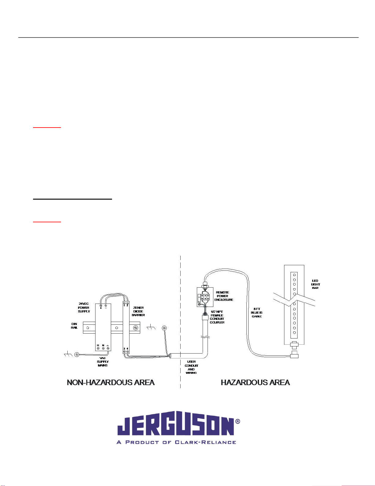
CAUTION:Before wiring LED illuminator, verify that the power circuit is off. The power supply and zener
diode barrier should be located in a non-hazardous area. The power supplied to the LED illuminator is
intrinsically safe. See figure 2.
Figure 2
IOM J500.32
Jerguson®LumaStar™2021.05
12
16633 Foltz Parkway ● Strongsville, OH 44149 USA ● Telephone: +1 (440) 572-1500 ● Fax: +1 (440) 238-8828
www.clark-reliance.com ● sales@clark-reliance.com
Enclosure Option
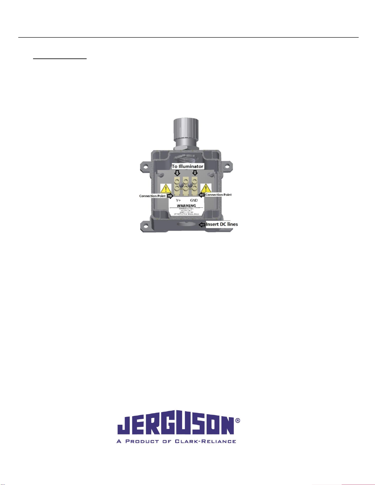
1. Open the cover of the connection enclosure. Insert the DC Line wires into the housing and connect to the
terminal block noting the polarity of the wire. The terminal block has been labelled with V + and GND to
aid installation. The DC output is pre-wired to the light bar. If this connection is removed during
installation, reconnect the white wire to V+ and green wire to GND. Failure to do so could result in
permanent damage to the power supply. Terminal torque value 4.5 LBF-IN. Wire size of #12-20 awg input
and Maximum of wire size of #18 awg output. See figure 3.
2. The cord length from the remote mount enclosure to the LED illuminator is 8 foot. Wire length from the
power supply and zener diode barrier to the remote mount enclosure is up to 1800 feet using 2 strand
#18 wire AWG. Longer distances available depending on wire choice. See specifications.
3. Replace the cover on the power supply housing.
4. Switch “ON” the power supply making sure the Illuminator is functioning properly, with all LED’s
illuminated.
5. Refer to the troubleshooting section in this manual if a portion or all of the LEDs do not illuminate.
Figure 3
IOM J500.32
Jerguson®LumaStar™2021.05
13
16633 Foltz Parkway ● Strongsville, OH 44149 USA ● Telephone: +1 (440) 572-1500 ● Fax: +1 (440) 238-8828
www.clark-reliance.com ● sales@clark-reliance.com
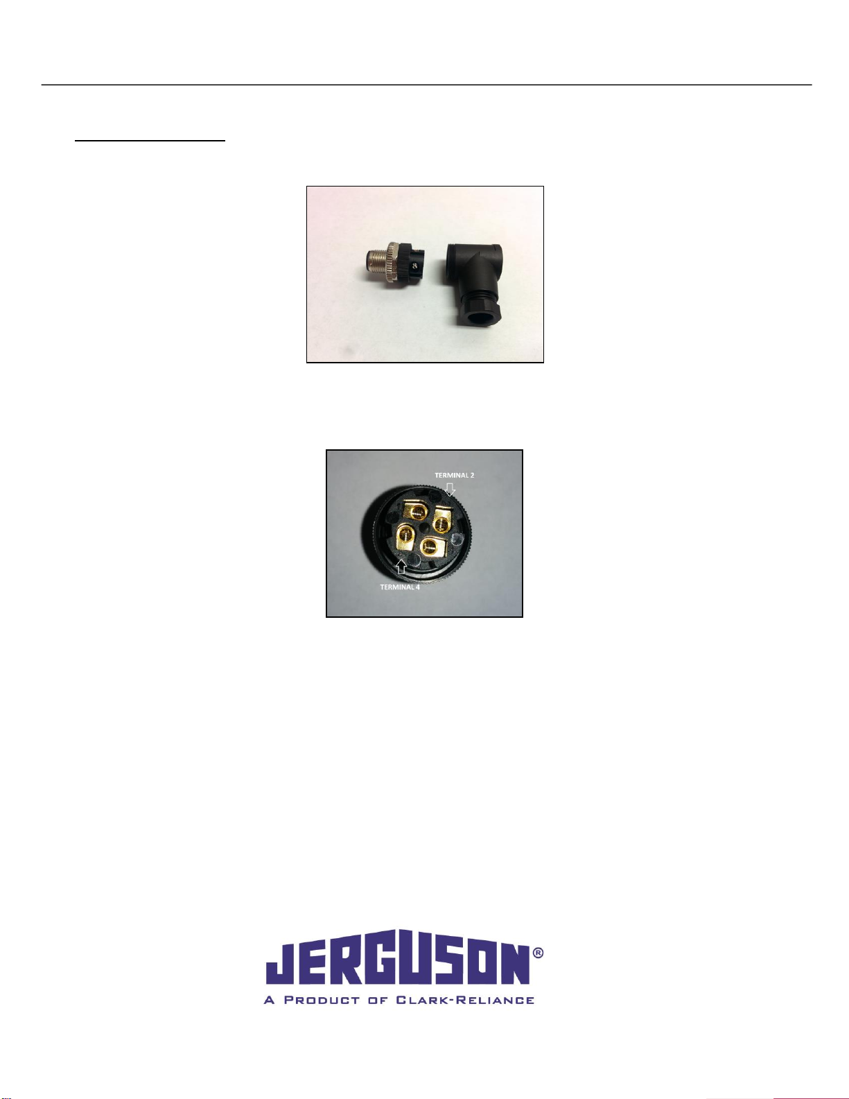
Field-Wireable Option
1. Disassemble the field-wireable connector. See figure 4.
2. Connect DC lines to the field-wireable connector, V+ to pin #2 and connect GND to pin #4. See figure 5.
3. Wire length from the power supply and zener diode barrier using 2 strand #18 wire AWG is up to 700 feet.
Longer distances available depending on wire choice. Maximum wire size of #18 AWG and cord size of 6-
8mm. See specifications.
4. Reassemble the connector and attached to led illuminator.
5. Switch “ON” the power supply making sure the Illuminator is functioning properly, with all LED’s
illuminated.
6. Refer to the troubleshooting section in this manual if a portion or all of the LEDs do not illuminate.
Figure 4
Figure 5

IOM J500.32
Jerguson®LumaStar™2021.05
14
16633 Foltz Parkway ● Strongsville, OH 44149 USA ● Telephone: +1 (440) 572-1500 ● Fax: +1 (440) 238-8828
www.clark-reliance.com ● sales@clark-reliance.com
Selecting Wire & Barrier
Selecting a wire with a lower capacitance (F) will yield longer distances. Use the following equations and diode
parameters below to determine the distance of wire between the LED illuminator and zener diode barrier. Pick the
shortest distance from the two following equations:
IMPORTANT: FARAD and HENRY units must be consistent throughout the equations. E.g.: all (uF),
not a mixture of (uF) and (F).
Cable Max Distance 1 = Total Allowable Capacitance (F) / [2 x Wire Capacitance (F)]
Cord Max Distance 2 = Total Allowable Inductance (H) / [2 x Wire Inductance (H)]
Diode Values for approved zener diode barriers:
Part Number
Manufacture
Manufacture Part
Number
Allowable
Capacitance (µF)
Diode Inductance
(mH)
V22098-1
R. STAHL
9001/01-280-110-101
.083
1.2
V22098-2
MTL
7728P+
.083
1.82
V22098-3
PEPPERL + FUCHS
Z728.H
.083
1.82
V22098-4
ALLEN BRADLEY®
937ZH-DPBN-1
.083
1.82
V22098-5
TURCK
MZB28P
.083
2.5
Routine Inspection
Keep window on the front of the light clean using a clean damp cloth. Avoid using chemical cleaners that may
damage the silicone seals. If cleaner is required, do not spray directly onto the light. Apply a small amount to the
rag and carefully wipe the glass only. Never use harsh abrasives, wire brushes, metal scrapers, or any material
that could scratch the window. The window may be cleaned while the unit is in operation.
IOM J500.32
Jerguson®LumaStar™2021.05
15
16633 Foltz Parkway ● Strongsville, OH 44149 USA ● Telephone: +1 (440) 572-1500 ● Fax: +1 (440) 238-8828
www.clark-reliance.com ● sales@clark-reliance.com
7.4 Troubleshooting
Troubleshooting Steps
CAUTION: Some of these troubleshooting steps are performed with live voltage applied. The assembly
should be moved to a safe area before beginning work. A qualified and properly trained technician
must perform these steps.
1. Verify Power supply has power.
2. Using a voltmeter set to DC; measure the voltage on the input of the barrier. Voltage should be 24VDC.
If no power is present, check wiring and repair or replace power supply.
3. Using a voltmeter set to DC; measure the voltage on the output of the barrier. Voltage should be
between 11VDC and 15VDC with the illuminator connected. 24VDC with no illuminator connected. If no
power is present replace barrier.
WARNING: DO NOT MEASURE VOLTAGE ACROSS INPUT AND OUTPUT. UNSAFE LEVEL OF CURRENT
COULD BE SENT INTO A HAZARDOUS LOCATION.
4. Verify wires are connected properly and no connections are loose.
5. Inspect wires for damage or loose connections. Replace as needed.
6. Unscrew blue power cord at LED bar. Inspect the 4 pins inside end connector to make sure they are
straight and undamaged. If pins are bent, use a small pair of needle-nose pliers to straighten bent pins.
If pins are missing, contact factory.
7. Reconnect power cord making sure connectors are fully seated and tightened.
8. If all steps above check OK, contact factory for support

IOM J500.32
Jerguson®LumaStar™2021.05
16
16633 Foltz Parkway ● Strongsville, OH 44149 USA ● Telephone: +1 (440) 572-1500 ● Fax: +1 (440) 238-8828
www.clark-reliance.com ● sales@clark-reliance.com
8. Bracket Installation (All Models)
8.1 Universal Bracket
*NOTE: Illuminators pictured are for reference only. The mounting instructions are the same across all Jerguson
Lumastarmodels. Model EPL-316 mounts in the same manner except the power supply is always remote
mounted.
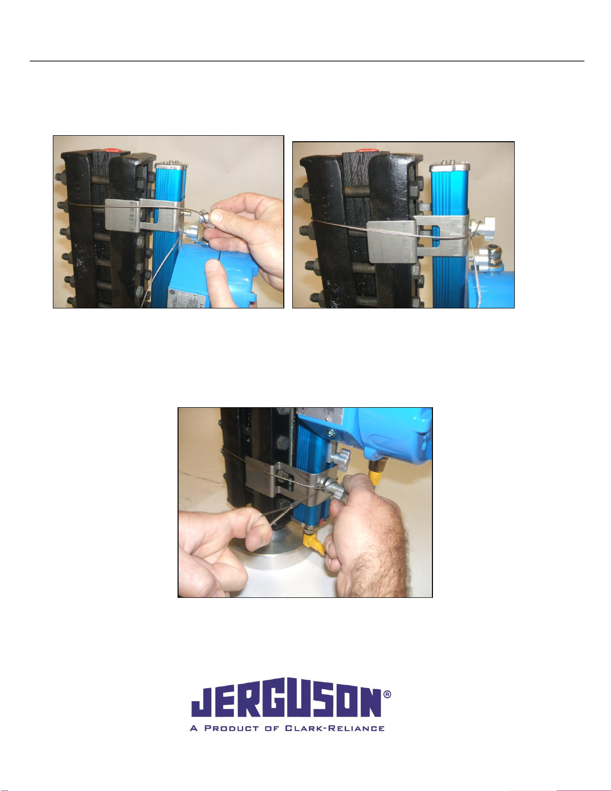
1. Check to make sure brackets are properly assembled on the illuminator. The cable should be fed through
the stud protruding from behind the illuminator, locking in the bracket as shown above in Figure 7. One end
of the cable should be crimped into an oval for pulling leverage and the other should be crimped securely
around a thumb nut.
Figure 6
Figure 7
Figure 8
IOM J500.32
Jerguson®LumaStar™2021.05
17
16633 Foltz Parkway ● Strongsville, OH 44149 USA ● Telephone: +1 (440) 572-1500 ● Fax: +1 (440) 238-8828
www.clark-reliance.com ● sales@clark-reliance.com
2. Press Jerguson®LumaStar™assembly against rear of gauge as shown in Figure 9, aligning the bracket
cutouts over the gauge bolt heads as shown. Align the brackets with the 2nd set of bolts in from each end of
the gage, when possible. Note that all one-section size 7 models and smaller will require the power supply
to be remote mounted.
F
3. While holding the top bracket in place, grab the thumb nut end of the cable, wrap around entire gauge and
thread onto the stud until the bracket is secure. When wrapping the cable around the gauge, make sure to
feed the cable above the bolt as shown above in Figure 10.Snug the cable and secure the thumb nut, but
do not fully tighten the thumb nut at this time.
4. Align bottom bracket, using the 2nd bolt if possible. Wrap thumb nut end of the cable around the entire gauge
and begin to thread. Pull the cable loop as tight as possible and fully tighten the thumb nut down as shown
in Figure 11. The lower bracket should now be tight and secure.
Figure 9
Figure 10
Figure 11

IOM J500.32
Jerguson®LumaStar™2021.05
18
16633 Foltz Parkway ● Strongsville, OH 44149 USA ● Telephone: +1 (440) 572-1500 ● Fax: +1 (440) 238-8828
www.clark-reliance.com ● sales@clark-reliance.com
5. After the lower bracket has been tightened, go back to the top bracket and loosen the thumb nut enough to
allow the cable to slide through freely. Pull cable as tight as possible, and fully tighten thumb nut as shown
in Figure 12.
6. The Jerguson®LumaStar™is now properly installed. Feel free to tuck any excess cable inside itself or allow
it to hang freely. This adjustable assembly is appropriate for any gauge with a cover width not exceeding
4.375 inches (111 mm).
Figure 12
Figure 13
Figure 14
IOM J500.32
Jerguson®LumaStar™2021.05
19
16633 Foltz Parkway ● Strongsville, OH 44149 USA ● Telephone: +1 (440) 572-1500 ● Fax: +1 (440) 238-8828
www.clark-reliance.com ● sales@clark-reliance.com
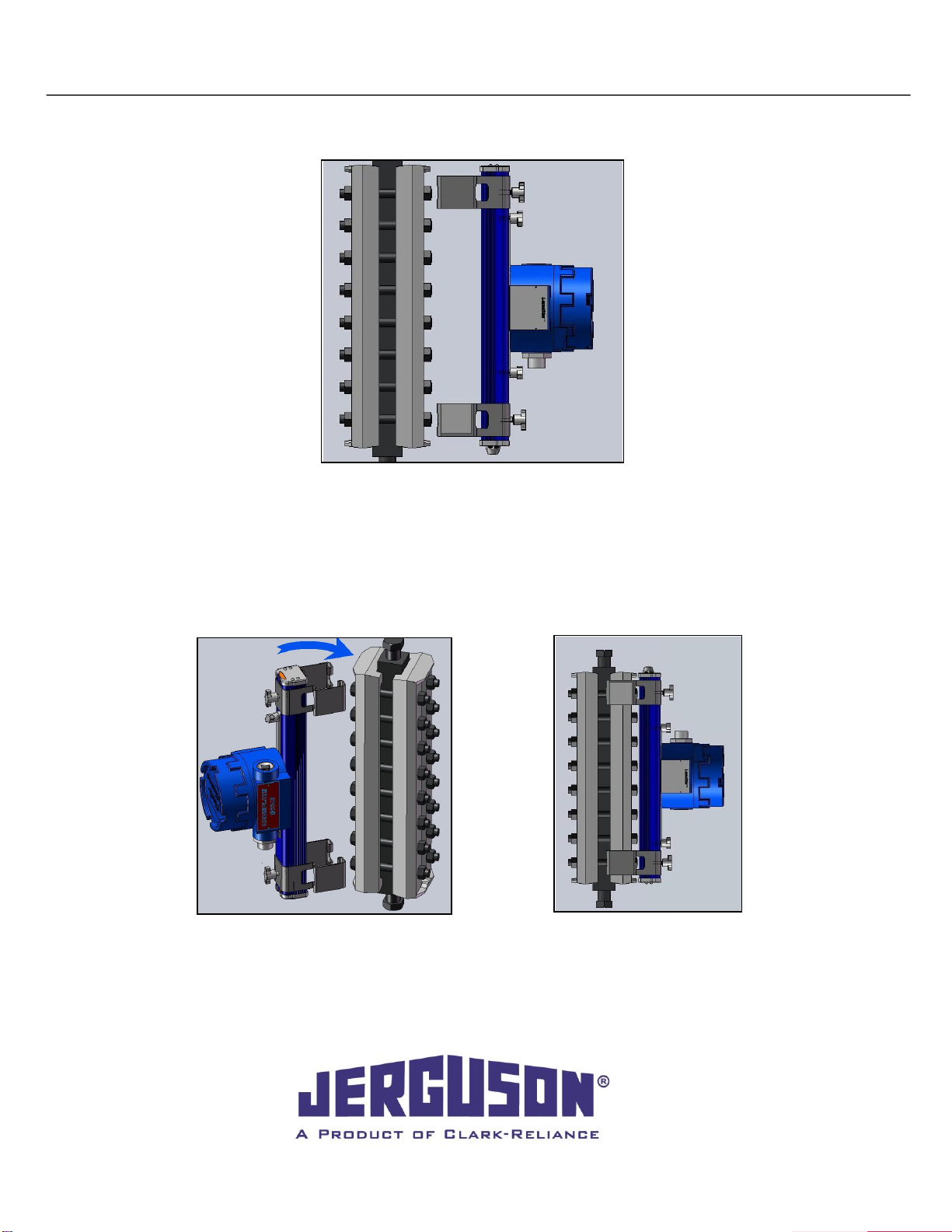
8.2 Alternate Bracket
1. Align Jerguson®LumaStar™assembly with rear (side with bolt heads) of gauge. Loosen bracket thumb
nuts and adjust the position of the brackets to line up with their respective bolts on the gauge. Tighten
the thumb nuts to secure in place. When possible, use the 2nd set of bolts from the edge of the cover
plate. Note that all one-section size 7 models and smaller will require the power supply to be remote
mounted.
2. Align one side of the brackets as shown in Figure 16, so that the clip of the brackets are gripping around
the side of the gauge. Roll the entire assembly over until it is flush with the rear flat of the gauge and
press until the bracket clips have locked into place as shown in Figure 17.
Figure 15
Figure 16
Figure 17
IOM J500.32
Jerguson®LumaStar™2021.05
20
16633 Foltz Parkway ● Strongsville, OH 44149 USA ● Telephone: +1 (440) 572-1500 ● Fax: +1 (440) 238-8828
www.clark-reliance.com ● sales@clark-reliance.com
8.3 Reflex Gage Bracket
.
NOTE: installation onto a Reflex Gauge requires removal of nuts on the gauge. Do not install illuminator
with gauge in service.
1. Install the brackets onto the illuminator leaving the bracket thumb screws loose. The brackets should
move freely up and down in the illuminator channel.
2. Remove top and bottom nuts from the Reflex Gauge on the side of the gauge that the illuminator is to be
installed on.
3. Position brackets onto studs, reinstall gauge nuts and tighten to the torque specified for your gauge.
4. Position illuminator so it is centered on the Reflex Gauge and tighten the bracket thumb screws. The
illuminator should be mounted as shown in Figure 18.
Reflex Bracket Mounting
Figure 18
Other manuals for LUMASTAR EPL-100
2
This manual suits for next models
1
Table of contents
Other Jerguson Industrial Equipment manuals


Popular Industrial Equipment manuals by other brands


Armorgard
Armorgard ducktrack DR1 user manual

SCHUNK
SCHUNK ROTA 2B Assembly and operating manual

Wilo
Wilo Wilo-Flumen OPTI-TR 20-1 Installation and operating instructions

Mold-Masters
Mold-Masters Hot Runner troubleshooting guide

Alfa Network
Alfa Network LU-VE Arctigo ISD Assembly instructions

Siemens
Siemens PolyBlend PB200-2 manual


