Rottler SG8 User manual

August 8, 2019
MANUFACTURING
SG8
SEAT AND GUIDE MACHINE
OPERATIONS AND MAINTENANCE
MANUAL
MANUFACTURED BY:
ROTTLER MANUFACTURING COMPANY
8029 South 200th Street
Kent Washington 98032 USA
Phone: (253) 872-7050
Fax: (253) 395-0230
NOTE: WHEN ORDERING REPLACEMENT PARTS,
PLEASE GIVE THE MODEL AND SERIAL NUMBER.
ORDER BY PART NUMBER.
THERE IS A MINIMUM ORDER OF $25.00

CHAPTER 1 INTRODUCTION / SAFETY / INSTALLATION:2-1
Introduction:................................................................................................................................................2-1
Limited Warranty:.......................................................................................................................................2-1
Safety Information:.....................................................................................................................................2-2
Electrical Power:.........................................................................................................................................2-2
Machine Operator:......................................................................................................................................2-2
Eye Safety:.................................................................................................................................................2-2
Work Area: .................................................................................................................................................2-2
Guards:.......................................................................................................................................................2-2
Overreach:..................................................................................................................................................2-2
Hand Safety:...............................................................................................................................................2-2
Machine Capacity:......................................................................................................................................2-3
Avoid Accidental Starting: ..........................................................................................................................2-3
Careless Acts: ............................................................................................................................................2-3
Job Completion: .........................................................................................................................................2-3
Replacement Parts:....................................................................................................................................2-3
Misuse:.......................................................................................................................................................2-3
Emergency Procedure:...............................................................................................................................2-3
Preparation for Placement:.........................................................................................................................2-3
CHAPTER 2 MACHINE INSTALLATION: 3-1
Location:.....................................................................................................................................................3-1
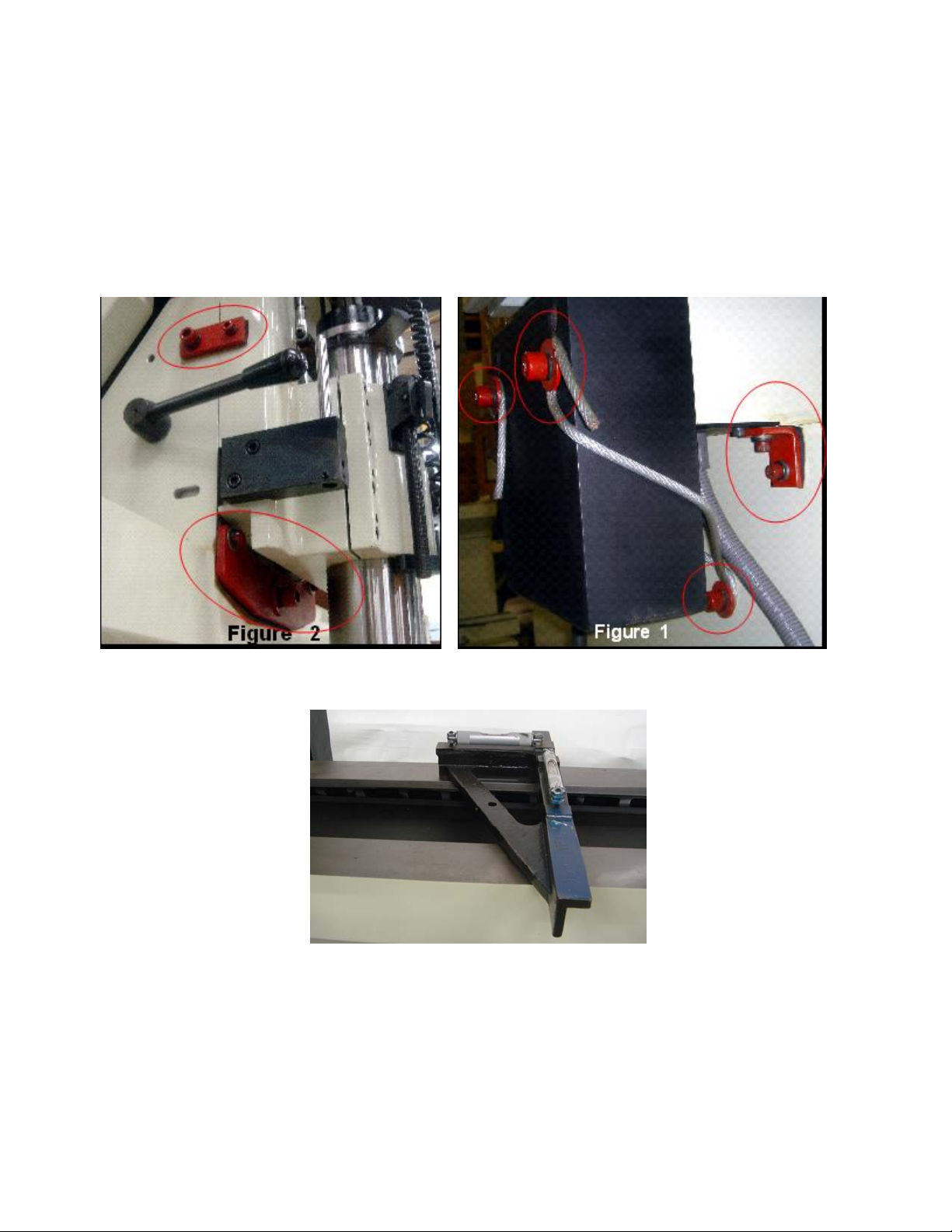
Unpacking: .................................................................................................................................................3-1
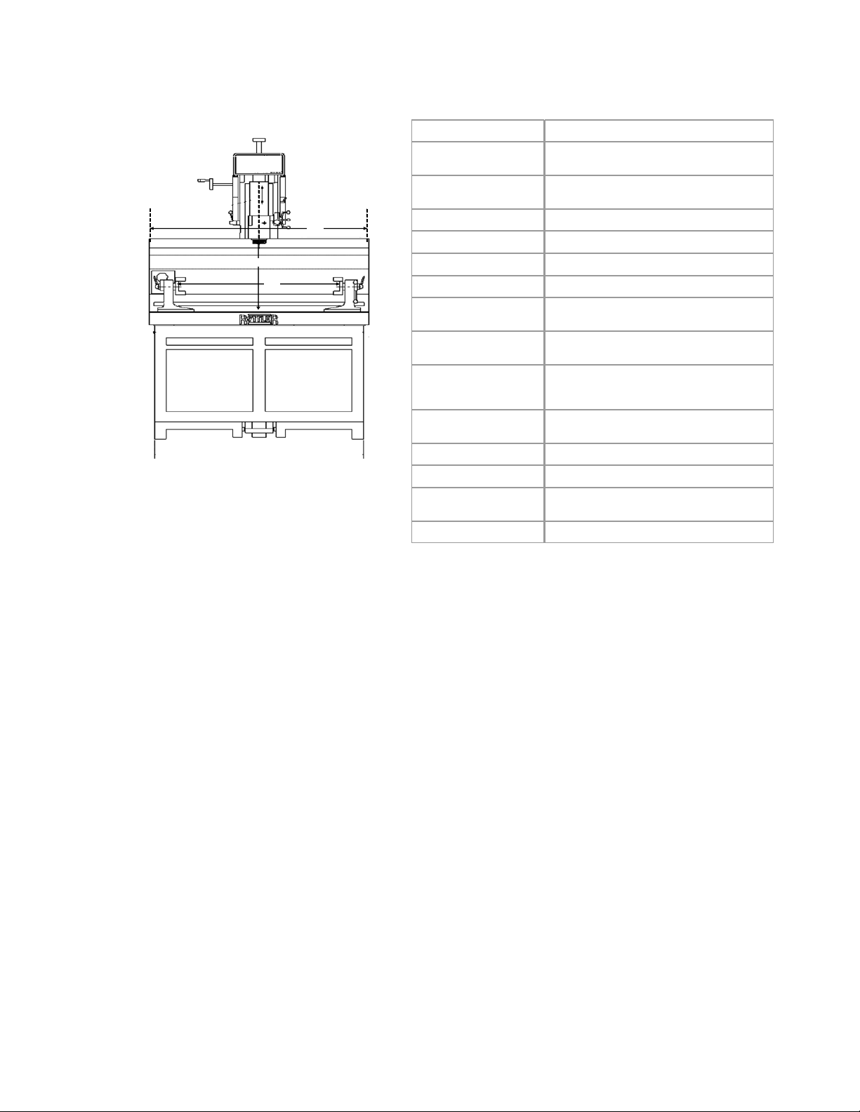
Positioning the Machine:............................................................................................................................3-1
Leveling the Machine: ................................................................................................................................3-2
CHAPTER 3 CONTROL DEFINITIONS:4-3
CHAPTER 4 OPERATING INSTRUCTIONS: 5-1
Mounting Cylinder Heads:..........................................................................................................................5-1
Alignment and Setup:.................................................................................................................................5-2
Front to Rear Cylinder Head Alignment:....................................................................................................5-2
Left to Right Alignment:..............................................................................................................................5-2
Selecting the right Pilot:..............................................................................................................................5-3
Three Angle Seat Cutting:..........................................................................................................................5-3
Cut seat only enough to clean up surface..................................................................................................5-3
Changing the Spindle Adapters: ................................................................................................................5-3
Installing the Spherical self Aligning toolholder:.........................................................................................5-3
CHAPTER 5 SPINDLE TO WORK: 6-4
Fine Feed Engagement:.............................................................................................................................6-4
Core Drilling and Reaming Valve Guides:..................................................................................................6-4
Cutting Counter Bores for Seat Rings:.......................................................................................................6-5
Tapping Operations:...................................................................................................................................6-5
CHAPTER 6 MAINTENANCE: 7-1

Calibrating the Digital Level: ......................................................................................................................7-1
The New Chip collector System:................................................................................................................7-1
CHAPTER 7 TROUBLESHOOTING: 8-1
Eccentricity Problems when Cutting Three Angle Seats:...........................................................................8-1
CHAPTER 8 WIRING DIAGRAM 9-1
Wiring Diagram...........................................................................................................................................9-1
CHAPTER 9 PNEUMATIC DRAWINGS 10-1
CHAPTER 10 MACHINE PARTS11-1
Base, Table and Riser Assembly.............................................................................................................11-1
WORKHEAD ASSEMBLY........................................................................................................................11-3
SPINDLE ASSEMBLY..............................................................................................................................11-1
TRANSMISSION ASSEMBLY .................................................................................................................11-4
HEAD SUPPORT ASSEMBLY ................................................................................................................11-6
CHAPTER 11 FIXED CARBIDE PILOTS ON STOCK 12-1
.375" Shank Diameter Fixed Carbide Pilots.............................................................................................12-1
CHAPTER 12 SEAT AND GUIDE CARBIDE INSERTS: 13-6
Carbide Profile Tips:.................................................................................................................................13-6

A
B
C
Note: Rottler reserves the rights to change any specifications
and over all product design out any notice.
SGF8 Specifications
DRIVE SYSTEM Double reduction two poly "V" belt
MOTOR Motor-180 volt DC 1 HP Baldor
Input voltage; 220V-single phase 50 / 60 Hz
SPINDLE ROTATION
SPEED Variable and reversible from 0 - 400 RPM
SPINDLE TRAVEL 8"
SPINDLE DIAMETER 3.150"
TAPER IN SPINDLE Rottler Special ISO - 30
SPINDLE TILT 15
o
± .01
o
in both directions for a total of 30
o
SPINDLE TO TABLE
CLEARANCE 16 ¼”
MAXIMUM WORK PIECE
HEIGHT A15” with Toolholder over the pilot
13” with Toolholder on the spindle
MAXIMUM CYLINDER
HEAD LENGTH ON 360º
ROLLOVER FIXTURE C
43” on out side locking handles
48" on inside locking handles
(unlimited without fixture)
OVERALL LENGTH ON
UPPER SURFACES 53”
OVERALL HEIGHT 83"
AIR REQUIREMENT 100 P.S.I.
FLOOR SPACE
REQUIREMENTS 33" deep x 93" wide
with tool box and sharpener
SHIPPING WEIGHT 2600 lbs. machine only

Operating Instructions 2-1 SG8 Manual
Chapter 2 Introduction / Safety / Installation:
Introduction:
This manual is divided into sections as listed in the table of contents.
It is required that the new user of the SG8 read this manual, in particular the sections concerning safety,
before operating the machine.
Limited Warranty:
Rottler Manufacturing Company Model SG8 parts and equipment is warranted as to materials and
workmanship. This limited warranty remains in effect for one year from the date of delivery, provided the
machine is owned and operated by the original purchaser and is operated and maintained as per the
instructions in the manual.
Tools proven to be defective within the warranty period will be repaired or replaced at the factory’s option.
We accept no responsibility for defects caused by external damage, wear, abuse, or misuse, nor do we
accept any obligation to provide compensation for direct or indirect costs in connection with cases covered
by the warranty.
Freight charges on warranty items (non-air shipment only) will be paid by Rottler Manufacturing for a period
of 60 days only from the date of installation or set-up by a qualified service technician or sales
representative.
Freight charges after the 60 day period are the customer’s responsibility.

Operating Instructions 2-2 SG8 Manual
Safety Information:
This machine is capable of causing severe bodily injury or death if EXTREME care
is not used when operating!
The operator of the SG8 should be a skilled machinist craftsman who is well versed in the caution, care, and
knowledge required to safely operate metal cutting tools.
The operator and nearby personnel should be familiar with the location and operation of the Emergency Stop
Button.
This manual has been prepared for the owner and those responsible for the maintenance of this machine. It’s purpose
aside from proper maintenance and operations is to promote safety through the use of accepted practice.
READ THE SAFETY AND OPERATING INSTRUCTIONS THOROUGHLY BEFORE OPERATING THE
MACHINE.
In order to obtain maximum life and efficiency from your machine; follow all the instructions in the operating
manuals carefully.
The specifications put forth in this manual were in effect at the time of publication. However, owing to Rottler
Manufacturing’s’ policy of continuous improvement, changes to these specifications may be made at any
time without obligation.
Electrical Power:
Make sure all electrical equipment has the proper overload protection. The SG8 should have a fully
isolated power supply to prevent damage and uncontrolled movement of the machine. If the SG8 is on the
same power lines that are running to other electrical equipment (grinders, welders, and other AC motors)
electrical noise can be induced into the SG8 electrical system. Electrical noise can cause the controller to
see false signals to move. Not supplying a fully isolated supply to the machine may void factory warranty.
Refer to the Power supply section later in this chapter for voltage and amperage requirements of the.
Machine Operator:
The operator of the SG8 should be a skilled machinist craftsman who is well versed in the caution, care, and
knowledge required to safely operate metal cutting tools.
Eye Safety:
Wear an approved safety face shield, goggles or safety glasses to protect eyes when operating the machine.
Work Area:
Keep the floor around the machine clean and free of tools, tooling, stock scrap and other foreign material and oil,
grease or coolant to minimize the danger of tripping or slipping. ROTTLER recommends the use of anti-skid
floor strips on the floor area where the operator normally stands and that each machine's work area be marked off.
Make certain the work area is well lighted and ventilated. Provide for adequate workspace around the machine.
Guards:
Keep all machine guards in place at all times when machine is in use.
Overreach:
Maintain a balanced stance and keep your body under control at all times.
Hand Safety:
NEVER wear gloves while operating this machine.

Operating Instructions 2-3 SG8 Manual
Machine Capacity:
Do not attempt to use the machine beyond its stated capacity or operations. This type use will reduce the productive
life of the machine and could cause the breakage of parts, which could result in personal injury.
Avoid Accidental Starting:
Make certain the main switch is in the OFF position before connecting power to the machine.
Careless Acts:
Give the work you are doing your undivided attention. Looking around, carrying on a conversation and
horseplay are careless acts that can result in serious injury.
Job Completion:
If the operation is complete, the machine should be emptied and the work area cleaned.
Replacement Parts:
Use only Rottler replacement parts and accessories; otherwise, warranty will be null and void.
Misuse:
Do not use the machine for other than its intended use. If used for other purposes, Rottler Manufacturing
disclaims any real or implied warranty and holds itself harmless for any injury or loss that may result from
such use.
Emergency Procedure:
Assuming one of the following has occurred: Work piece or spindle base not clamped, depth of cut not set
correctly, these mistakes will become obvious the minute the cut starts
PRESS THE EMERGENCY STOP BUTTON (on the front control panel) IMMEDIATELY!
“REMEMBER” metal cutting tools have the speed and torque to severely injure any part of the human body
exposed to them.
Preparation for Placement:
Air supply is connected at the right, rear of the machine, at base of upper casting. Connection can either be a
quick disconnect or permanent threaded connection. Be certain to use an adequately sized air line,
permitting proper operation of float. Air pressure should never drop below 90 PSI at any time. Failure to
provide adequate air supply may cause improper floating and clamping.
At this time, some customers will install a T fitting or manifold at the regulator, allowing another air hose to be
connected, providing a connection point for air tools. The auxiliary hose, if fitted, should be of sufficient
length to easily reach the entire front of the machine.
This machine comes pre-wired and ready to be connected to the power source. The power source should
meet all local and national electrical codes. This service should connect to its own circuit breaker or fuse. In
most cases the machine will require 220 VAC, 15 amp, single-phase service but you should verify voltage
requirements by inspecting the electrical tag located on the rear of the machine.

Operating Instructions 3-1 SG8 Manual
Chapter 3 Machine Installation:
Location:
The productivity of this machine will depend a great deal on it’s proper initial installation, particularly the
means by which cylinder heads are lifted into the machine as well as the material handling to and from other
operations in your shop.
The proper loading arrangement and location for your SG8 machine is extremely important.
A slow travel (6 to 10 feet / min.) power hoist operated from either a bridge crane or a jib crane arrangement
works very well.
Unpacking:
Carefully uncrate the machine. Remove all tooling from storage compartments and unpack. Locate the
leveling bolts and leveling pads. Clean all surfaces with solvent and rags to remove protective shipping
coatings.
Positioning the Machine:
Machine is very top heavy. Extreme caution should be used at all times when lifting
and positioning the machine!
.Move the skidded machine as close as possible to its final location.
Remove shipping bolts securing machine to pallet. Using the forklift cut-outs provided in base of machine,
raise machine above pallet and remove pallet from under machine. When lifting machine alwaysmakesurethat
forks protrude all theway under and extend beyond the base of the machine.
At this time the machine should be lowered and adequately supported so as to allow access inside of cabinet to install
the front leveling bolts. Jam nuts should be installed on the leveling bolts then the bolts should be threaded
through from the top side. Install leveling bolts at rear of machine in the same fashion.
Raise the machine and move carefully to the final location. Be certain to allow sufficient clearance to allow access
for leveling and also for connecting air and electrical lines. Lower machine onto levelingpads makingcertainthat
the leveling bolts engage into counterbore on leveling pads.
Be certain nothing interferes with air or electrical lines running from the floating head assembly to the cabinet.
Determine there is no possibility of air or electrical lines dragging on wall surfaces or adjacent machinery.

Operating Instructions 3-2 SG8 Manual
Leveling the Machine:
Before leveling the machine, loosen and remove the shipping brackets securing the air float Workhead.
(Figures 1 & 2). The air float clamp plate bolts may need to be loosened also. Access to these bolts is gained by tilting the
spindle assembly to the left and loosening the bolts on that side approximately 1 turn. Access to the right side
bolts is obtained by tilting the spindle to the right. Caution: Do not loosen more than necessary to allow the head to
float. Clamp assembly will not clamp tight if bolts are loosened too much. It is best to hold nylock locking nut secure on
topside and loosenbolt with wrench from underside of clamp plate.
Required machinist level. (Starret 98 or better).
Use the level on the upper float surface, level the machine as precisely as possible, front to back and sideto
side. Level is obtained fastest when using a three point leveling method. Toutilize a three point leveling method, use only
the front outside leveling bolts and the middle bolt in the rear. Use a socket wrenchtoturnthelevelingbolts.After
the machine is leveled bring in the other leveling bolts. Be certain all leveling bolts are effectively supporting the
machine. Tighten jam nuts on leveling bolts and recheck level.

Operating Instructions 4-3 SG8 Manual
Chapter 4 Control Definitions:
SGF8 Control Definitions
SPINDLE TILT LOCK
DIAL DEPTH INDICATOR
SPINDLE HANDWHEEL
FINE FEED HANDWHEEL
DIGITAL LEVEL PICKUP
SPINDLE TILT LOCK
POSITIVE DEPTH STOP
POWER OFF SWITCH
DIGITAL LEVEL READOUT
SPINDLE DIRECTION
LAMP SWITCH
HALOGEN LIGHT
SPINDLE TILT HANDWHEEL
SPINDLE START SWITCH
RPM INCREASE SWITCH
RPM DECREASE SWITCH
SPINDLE RPM READOUT
SPINDLE SELF LOCKING NUT
SPINDLE DAMPER

Operating Instructions 5-1 SG8 Manual
Chapter 5 Operating Instructions:
Mounting Cylinder Heads:
Initial clamp height adjustments to the head trunions can be accomplished by measuring the head thickness
then raising the turning clamping block assembly to the appropriate height using the clamping block acme
screws. A 5/16”t-handle allen wrench works well.
Measure the length of the cylinder head. Spread the trunion assemblies apart from each other so that the
cylinder head can be clamped in between the trunions.
Each support has an adjustable stop, located to the front. The stops have indents, allowing a number of
different settings. Position of the stops must be checked for each cylinder head put on the supports. In most
cases we will install the cylinder head deck side down with the exhaust side of the head against the
adjustable stops. This is particularly true of wedge style heads. It is necessary for the clamps to thrust the
cylinder head against the stops when clamped. When heads are mounted in this fashion, the tallest portion
of the combustion chamber will be at the rear of the machine when the head is rotated into the working position.
Try to keep the valve guide center line parallel to the trunion centerline. (Figure 4)

Operating Instructions 5-2 SG8 Manual
Utilize the grooves in the table to align the trunion supports square to the machine.
The Rottler-Klamp head mounting fixture is provided to accommodate cylinder heads that are difficult to mount
directly into the trunions. Some machine operators prefer to use the Rottler-Klamp fixture for the majority of heads
as the mounting is very quick. The Rottler-Klamp frame is mounted between thetrunionsand clampedusingthe
clamping plates. (Figure 5) The cylinder head is then held to the frame with the swivel clamp assemblies through the
appropriate head bolt holes.
Alignment and Setup:
Alignment and setup applies to both the cylinder head and the machine’s floating head. The goal is to
perfectly align the spindle centerline to the centerline of the area of the head to be machined. Most machining
operations on cylinder heads use the valve guide centerline as the referencepoint so we will use that as an example.
Note: think of the digital electronic level as a comparator. Because the leveling pin is square to the
machines spindle, as long as you achieve the same readings front to rear and side to side then the spindle will be in
perfect alignment.
Front to Rear Cylinder Head Alignment:
Position the level on level pin to read front to rear and take a reading. Rotate the cylinder head so that the
valve seats are facing up. Now place the level on a pilot in the cylinder head and position the level to read front to rear.
Loosen the lock levers on the supports. Be certain the fine adjustment lock screw is loosened. Coarse adjustment
is made by turning the work piece manually, until the level reading is withinacoupleofdegreesofthereading on the
leveling post.
Lightly tighten the lock levers on the supports to remove any play. Now tighten the clamp on the fine
adjustment screw. Turn the adjustment knob to achieve the exact reading that was observed on the leveling
post. You can now completely tighten both the left and right support locks.
Note: An optional alignment bar is available that helps establish the front to back alignment on canted
valve cylinder heads. The bar is held against two pilots in two adjacent guides. Use the alignment post to adjust
the angle.
Left to Right Alignment:
Obtain the left to right reading from a pilot mounted in a guide in the cylinder head. Now place the level on the leveling
post . Loosen both of the tilt lock levers on each side of the quill housing. Use the tilt adjusting hand wheel to
adjust the reading to be the same as that found on the pilot in the cylinder head. Tighten the tilt lock levers.

Operating Instructions 5-3 SG8 Manual
Selecting the right Pilot:
IMPORTANT: the pilot is the only link between one fixed part - the clamped cylinder head and pilot and a
moving and heavy part, the workhead.
The centering accuracy and the machining accuracy depend on the carbide pilot you select.
Choosing the right pilot will ensure the accuracy of the machining.
The pilot is selected according to the actual guide and not according to the original guide diameter or the
valve stem diameter.
Three Angle Seat Cutting:
Place the ball drive adapter in the spindle.
Align spindle to valve guide.
Place a valve in the setting fixture. Position the pointer on the
valve where you wish to place the top of the seat.
Remove the valve; replace it with the correct pilot.
Select the proper diameter tool holder. Place the carbide insert
in tool holder. Slide tool holder onto ball head.
Place ball head over the pilot in setting fixture. Use radial
adjusting screw to set diameter of cutter to correspond to
position of pointer on setting fixture. Tighten hex socket screws
on bottom of ball head. See figure 9
Remove ball head assembly from setting fixture. Place fixed
carbide pilot in cylinder head.
Center the spherical ball head toolholder over the pilot shank.
Required spindle rotation speed will vary, depending on seat
hardness. As seat hardness increases, so does the required spindle
speed. Some will require full speed.
Special care should be taken in centering the floating head
above the valve guide, to achieve a concentric seat.
Cut seat only enough to clean up surface.
Too much cutting will sink the valve too far in the head. Many
operators prefer to use the spindle fine feed when machining
seats as extreme control of spindle down feed can be
accomplished.
Changing the Spindle Adapters:
Once that you have the toolholder setup, fit the ball head toolholder into the spring free spindle adapter.
The SG8 spindle was engineered to allow ultra fast tooling changes .Make sure the that spindle spring free
locking nut is in the off lock position, line up the two ears of the spindle adapter and insert into the spindle
ISO 30 taper, the locking nut automatically will be on the lock position, to remove turn the self locking nut to
the left position, hold the spindle adapter, it may drop on the machine table. Damage will result.
Installing the Spherical self Aligning toolholder:
Once the spring free adapter is in the spindle, fit the Rottler Spherical Self aligning Toolholder
assembly into
the spindle adapter; make sure to align the locator pins before you fit it into the spindle adapter and push it
until you feel that is lock.

Operating Instructions 6-4 SG8 Manual
Chapter 6 Spindle to Work:
When the cylinder head is clamped properly on the table
and adjusted, move the workhead to the first valve guide
by pushing on the food pedal.
At this point the spindle and workhead should be level
according to the position of the cylinder head.
Most machining operations require the spindle to be directly
centered over the work to be performed. This is usually
accomplished by air floating the workhead above the area
to be machined then manually lowering the spindle to the
pilot shank with the spindle adapter sleeve on the down
position, once that you have the toolholder about ½” in to
the pilot shank release the sleeve to the upper position to
achieve perfect centering according to the position of the
pilot and lower the toolholder into the pilot manually until
reach the proper height or until the carbide tip is a few
thousands from the seat. Do not make contact with the seat surface, the work head should be floating at all
the time; once it’s down release the foot pedal to Note: when machine the seat, the sleeve should be in
upper position. The work head should be in float mode at all times
If the pedal is released too quickly, the float head may bounce. True centering may
not be achieved if this happens. Slowly releasing the air float pedal gives the best results. Removing your
hands completely from the work head during the final seconds of centering will insure that you do not
negatively influence centering accuracy.
Fine Feed Engagement:
To engage the fine feed mechanism it is necessary to push
inward on the spindle feed handwheel while rotating the fine
feed handwheel until engagement is achieved. To disengage the
fine feed simply pull outward on the spindle feed handwheel.
Core Drilling and Reaming Valve Guides:
A special drive adapter is supplied to accept core drills and reamers.
Align core drill with valve guide by inserting core drill pilot in guide as head of machine is floated and centered
Push green button Spindle Start to start the spindle, verify correct rotation. Operate at 85 RPM, feed
with moderate pressure until it clears the bottom of the guide.
Raise Quill to bring core drill above upper end of valve guide. Stop spindle by pushing Spindle Start
button. Select and install correct reamer. Repeat step 2 at 150 RPM.

Operating Instructions 6-5 SG8 Manual
Cutting Counter Bores for Seat Rings:
Align the work piece as explained previously. Cylinder head deck surface must
be up.
Insert correct pilot into the valve guide. Mount the correct milling head cutter
on the milling head Adapter, Install milling head adapter into spindle adapter
Float the machine workhead while feeding the spindle down into the pilot until
milling head is few thousand from contacting the seat, release the foot pedal to
lock the floating head, rest the cutter gently on the surfaces and set the positive
stop with the seat ring between the stop rod and the quill clamp. This will ensure that
quill travel will be limited to the correct amount; or use the following alternative
method:
Set dial indicator for feed depth to zero, being certain the indicator has
sufficient travel to allow the proper depth of cut.
Push the green Spindle Start button to start the spindle rotation. Turn the spindle at
approximately 80 RPM - larger seats may require a slower speed; smaller seats may be run faster. Observe dial
indicator or positive stop. Cut to proper depth.
Swing the indicator out of the way after completing the procedure.
.
Tapping Operations:
Place the Jacobs chuck or Collet Holder in the spindle as explained previously. Install tap in the chuck, and
tighten.
Center over the hole to be tapped
Push green button Spindle Start to start rotation of the spindle and feed down the hole.
Choose a spindle speed sufficient for the tap (approximately 50 RPM), and allow the tap to feed the spindle
as it threads the hole.
When the proper depth is achieved, press to reverse the spindle rotation and left spindle return the
tap off the hole.

Operating Instructions 7-1 SG8 Manual
Chapter 7 Maintenance:
Calibrating the Digital Level:
NOTE: Even though the level has been carefully calibrated at the
factory, it is a good idea to recheck calibration before putting the
machine into service. In the event that the level is dropped or handled
roughly then the following recalibration methods should be
implemented.
The level assembly is referenced to the spindle via the level pin. It is
important to check alignment of pin in reference to the spindle. This is
accomplished by mounting a magnetic base dial indicator to the
machine spindle and sweeping the pin vertically by raising or lowering
spindle to check alignment. Pin alignment should be checked in two positions
at 90 degrees to each other. If the pin alignment needs correcting, do
so with the set screws located at base of pin block.
Install level on pin. Orient level to read left to right. Tilt head left or right
until level reads 0.00. Now rotate level 180 degrees. The reading
should be 0.00, if not then it will be necessary to calibrate the
inclinometer to the level body. This is accomplished by loosening the
inclimeter’s two retaining screws and pivoting the inclimeter until it
repeats when level is rotated 180 degrees. Example: level reads 0.04
to the left, when rotated 180 degrees to the right it should read minus
0.04.
Check the level reading with the pickup oriented front to back. It should read 0.00 if the machine has been
properly leveled with a machinist level.
If the LED does not read 0.00 then chances are the machine’s leveling procedures have not been properly
followed or there are internal problems with the level’s electronics.
The sensitivity of the level is so great that it may not zero totally, even while the machine is not being
touched. The alignment tolerance for installing guides is plus or minus .04 degrees, and for formingthreeangle
seats is plus or minus .08 degrees.
The New Chip collector System:

Troubleshooting 8-1 SG8 Manual
Chapter 8 Troubleshooting:
Eccentricity Problems when Cutting Three Angle Seats:
Spindle floated to improper center location.
Excessive pressure when machining the seat.
Incorrect spindle speed.
Worn or improperly selected pilot.
Worn Valve Guide.

Machine Parts 9-1
SG8 Manual
Chapter 9 Wiring Diagram
Wiring Diagram

Machine Parts 10-1
SG8 Manual
Chapter 10 Pneumatic Drawings

Machine Parts 11-1 SG8 Manual
Chapter 11 Machine Parts
Base, Table and Riser Assembly
BASE, TABLE AND RISER ASSEMBLY
28
27
26
PLATE NO. -1
34
29 35 36
38
37
19
13
22
14 15
16
11
10
98
12
21
18
20
6
7
SGF-8
33
31
30
32
17
24
25
23
2
1
5
4
3
THE
CUTTING
EDGE
This manual suits for next models
1
Table of contents
Other Rottler Industrial Equipment manuals

Rottler
Rottler SM Series User manual

Rottler
Rottler VR9 User manual

Rottler
Rottler P69 User manual

Rottler
Rottler SA Series User manual

Rottler
Rottler DA-4SB Assembly Instructions

Rottler
Rottler SAD Series User manual

Rottler
Rottler HP 7A User manual

Rottler
Rottler SG9A User manual

Rottler
Rottler SG10XY User manual

Rottler
Rottler EM69P CNC 5 AXIS User manual