Spectra Precision LL100N User manual

Laser Levels Online
Spectra RC601 Remote Control
REVISION 1.0
User Guide
© 2021 Laser Levels Online

RC601UK REMOTE CONTROL
2
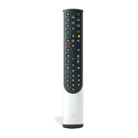
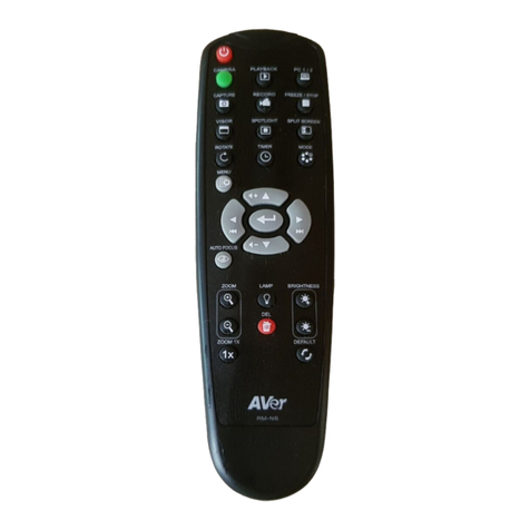
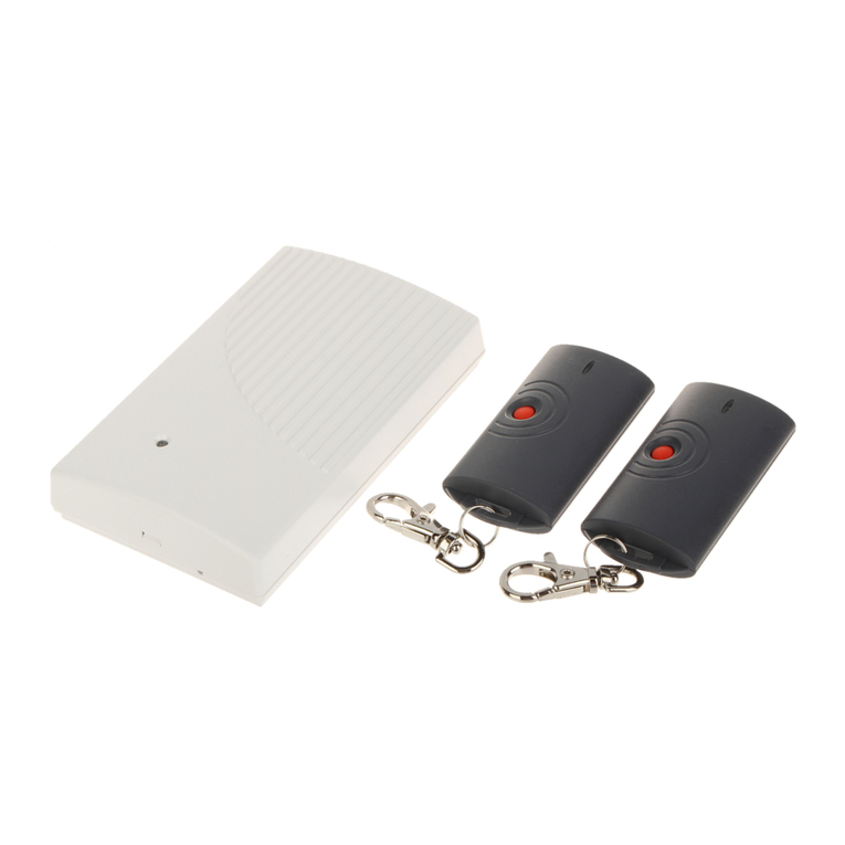
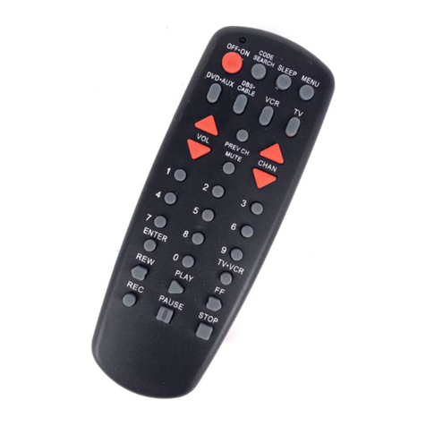
The Spectra RC601UK Infrared Remote Control enables the user to remotely (up to 30m), adjust
the following settings: Rotational speed, Scan angle & position, Manual Override (for single or
dual-axis grade/slope control). It cannot be used to turn the Laser ON or OFF (a feature not
available on any Spectra laser level system).
It is compatible with the Spectra LL100N, Spectra HV101 & Spectra LL300N only.
However, not all remote functions are available on all models of laser.
HV101 Scan Mode
(Stop Dot, 3°, 8°, 45°,
90° & 180° Line)
HV101 Rotational Speed Control.
Zero (Stop Dot), 50, 200, 600rpm
LL100N, HV101 & LL300N
Up / Down / Left & Right Arrows
(Grade / Slope Controls)
LL100N, HV101 & LL300N
Manual Override
(Disables Self Levelling!)

RC601UK REMOTE CONTROL
3
Power Supply & Battery Replacement
●The RC601UK is powered by 1 x 9v PP3 alkaline battery which will be pre-installed.
●When required, unscrew the rear battery compartment and t 1 x 9v PP3 alkaline
replacement battery, taking care to ensure correct polarity.
HV101
Rotational Speed Control
●Press the Rotational Speed Control button on the face of the laser or on the remote to cycle
through the 4 rotational speeds.
●The rotational speeds are Zero (Stop Dot), 50, 200, 600rpm.
●For Indoor work, we suggest using slower speeds, where the laser beam is easier to see by
eye; but for Outdoor Groundworks – run the HV101 at its maximum speed of 600rpm; which
gives the best working range when used with the supplied Laser Detector.
●The default rotational mode is 600rpm when the laser self levels after being turned on.
The following general guidance is only applicable to: Spectra HV101.
Scan Mode
●Press the Scan Mode button on the face of the laser or on the remote to cycle through the 6
scan modes. Each mode adjusts the angle of the beam.
●The scan modes allows the user to set a Stop Dot, 3°, 8°, 45°, 90° & 180° Line
●The scan mode is typically only used indoors and enables the user to see the beam better in
a specic position.
●The Detector cannot pickup the Laser beam when in scan mode.
●Pressing the Rotational Speed Control button once will turn o scan mode and return the
laser to rotating at 600rpm.

RC601UK REMOTE CONTROL
4
LL100N, HV101 & LL300N
The following general guidance is applicable to: Spectra LL100N, HV101 & LL300N.
Manual Override
●Press the Manual Override button on the remote once and the self levelling system will be
turned o. The Laser will continue to rotate but the laser will no longer be outputting a level
datum.
●This mode is typically enabled when the laser is being used to do Gradients and Slopes (See
Gradients & Slopes section on page 6 for further details).
●Pressing the Manual Override button once more will turn the self levelling system back on.
The Laser head will stop and adjust to a level datum and then begin rotating at 600rpm. The
laser is now running in self levelling mode once more.
Up / Down / Left & Right Arrows
●When the LL100N, HV101 or LL300N is in manual mode (Self levelling system has been
turned o), the Up / Down / Left & Right arrows are used to tilt the laser prism in either the X
or Y axis to set a progressive fall or gradient. (See Gradients & Slopes section on page 6 for
further details).
Grading
●The LL100N, HV101 & LL300N are all DUAL GRADE facility laser levels when using the Remote
Control. This means that they can be switched to “Manual” (to override the self levelling
system) allowing the user to set a grade (incline/slope) in the X axis only, Y axis only or both
together. The maximum settable slope is an approx. fall of 1m over 10m.
●For X & Y alignment, please see the case markings on the TOP of the laser head where sights
point in the direction of the axis being set.

RC601UK REMOTE CONTROL
5
LL100N, HV101 & LL300N
The following general guidance is applicable to: Spectra LL100N, HV101 & LL300N.
Setting Single Axis Slope
●This example sets a grade in the X axis.
●Press the ON/OFF button once and the Laser will power on and begin automatically self-
levelling.
●Press the Manual Override button on the remote once and the self levelling system will be
turned o & the red HI / MAN LED illuminates and begins ashing.
●Using the black Left & Right Arrow buttons on the remote, set the % slope (fall) required - as
measured on your sta.
●When complete, press the Manual Override button once more and this will turn the self
levelling system back on. The Laser head will stop and adjust to a level datum and then begin
rotating at 600rpm. The laser is now running in self levelling mode once more.
Setting Y Axis Slope
●This example sets a grade in the Y axis.
●Press the ON/OFF button once and the Laser will power on and begin automatically self-
levelling.
●Press the Manual Override button on the remote once and the self levelling system will be
turned o & the red HI / MAN LED illuminates and begins ashing.
●Using the yellow Up & Down Arrow buttons on either the face of the laser or on the remote,
set the % slope (fall) required - as measured on your sta.
●When complete, press the Manual Override button once more and this will turn the self
levelling system back on. The Laser head will stop and adjust to a level datum and then begin
rotating at 600rpm. The laser is now running in self levelling mode once more.
Setting Both X & Y Axis Slopes (Dual Grade)
●Proceed as above, but use all four Arrow buttons on the remote - as required.

HOW TO SET SLOPES (FALLS/GRADES)
6
Working Example
The following description in this guide, explains the general principles of setting a Slope (Fall/
Grade) when using a Spectra Rotary Laser Level with the Spectra RC601UK Remote Control.
Equipment
You will need the Laser Level, a surveying tripod, measuring sta (rod) with mm scale and a laser
detector/receiver. You will also need the remote control or if you have arrow keys on the laser
keypad those can be used instead. If your Laser Level does not have arrow keys on the Laser
keypad, you will also need a remote control as you cannot set a gradient and slope without
this.
Site Conditions
There are many dierent work site scenarios. As an example, we are assuming that you are
outside on a site with a clear eld of view and planning to set drainage falls.
All above ground and below ground drainage pipes should be laid to an adequate gradient. The
fall in a pipe is dened as the vertical height by which the pipe drops over a known distance. e.g.
a 2.5% gradient is a fall of 1m over 40m or 1:40. (1 in 40).
Typically, surface water or foul water drainage pipes are set between 1:40 to 1:80.
If a gradient is too steep i.e. steeper than 1 in 40, the liquid may run faster than the solids in a
foul water pipe thus leaving the solids stranded, which could then block the pipe. Conversely,
if a gradient is not steep enough (usually less than 1 in 110), then the pipe may still block, if the
solids slow down and become stranded.
Procedure
Place the Laser Level horizontally on the surveying tripod, switch it ON and allow it to auto (self)
level. Note the X-axis / Y-axis markings on the top cover of the laser.
Setting a 1:40 gradient: Position the measuring sta at 10m away from the tripod, held
vertically and move the laser detector (receiver) along the sta to nd the set level position,
usually by giving a continuous audible tone. By proportion, a 1m fall at 40m is only 250mm
at 10m, so carefully noting the set level dimension on the rear of the sta, move the detector
down by 250mm and clamp tight.
Using the remote control (from the sta location) or a colleague at the laser, press the Manual
Override button and have the axis to be adjusted facing the measuring sta.
Hold the “down arrow” button on the remote control or laser’s keypad, to slope the laser beam
down the measuring sta until it gives a continuous tone again, having found set level on the
detector. This has now set a 1:40 fall.
Return the laser detector to the original set level dimension on the sta.
Dig out ground & lower sta until the laser detector picks up the laser beam again.

HOW TO SET SLOPES (FALLS/GRADES)
7
Working Example (Continued)
Important note: All “grade facility” rotary lasers revert back to the auto (self) level condition if
switched O without retaining the gradient set. So its recommended to complete the ground-
works before switching the laser O.
Once this 1:40 fall is set, the User can use this inclined laser beam as a datum to set the depth of
either the crown of the drainage pipe or the Invert level, anywhere in range of the laser – along
that same axis.
Invert level of a pipe – is the level taken from the bottom of the inside of the pipe.
Crown of a pipe – is the Invert level plus the internal diameter of the pipe plus the pipe wall
thickness. It may be necessary to use this in calculations when level measurements are taken
from the crown of a pipe.
Manhole / Access Chambers:
A manhole or access chamber is required to gain access to a drainage system for un-blocking,
cleaning, rodding or inspection. (Land drainage systems excluded). They can be manufactured in
PVC, masonry or pre-cast concrete.
When setting appropriate drainage gradients it is important to allow for the depth down to
either the crown of the pipe (or the Invert level) from ground level, when using these manholes.
Dual Grading:
A rotary laser level with dual grading facility can be used for setting out driveways, car-parks or
areas with slopes (falls) in BOTH the X & Y axis.
The same procedure is adopted as above for drainage runs, except a second step in the process
is undertaken to set the laser to a fall in the other axis, to complete the dual grade setting-out.
Cut & Fill Machine control work:
If slopes of more than 10% (1:10) are required, which is outside the range of electronic
adjustment of the rotary laser’s prism; then simply switch the laser to Manual & t a “Laser
Grade Adapter” between the top face of the tripod & the base of the laser. Then set the required
slope. Search our website for more details.

Laser Levels Online
MAGNETIC MACHINE DETECTORS
Check Out Our Range Of Magnetic Detectors
Unit 35, Bridge Business Centre, Beresford Way, Dunston Road,
Chestereld, Derbyshire, S41 9FG, United Kingdom
Freephone: 08000 869 769 (Free from UK mobiles and landlines)
Put a Magnetic Detector / Receiver on your machine and extend the benets of any red beam
rotary laser. They are reliable, simple to attach, extremely robust and easy to use.
www.laser-level.co.uk/magnetic
Other manuals for LL100N
2
This manual suits for next models
4
Table of contents
