Spectris Bruel & Kjaer Vibro AC-2114 User manual

© Brüel & Kjær Vibro ● C107834.001 / v01 ●Seite/Page 1 von/of/de 16
Technische Änderungen vorbehalten! / Technical alterations reserved! / Spécifications techniques sous réserve de modifications!
UNRESTRICTED DOCUMENT
AC-2114
Schutzgehäuse mit Sichtfenster
Protective Housing with Window
Coffret de protection avec Fenêtre
Abbildung / figure / figure 1
AC-2114 geschlossen / closed / fermé
Anwendung
Application
Utilisation
Das AC-2114 ist ein Schutzgehäuse
mit Deckel mit Sichtfenster für den
Einbau von Messelektroniken
(z.B. Serie VC-18xx).
Der Deckel des Schutzgehäuses ist
mit zwei Scharnieren ausgestattet und
mithilfe zweier Schrauben
verriegelbar.
Es dient zur Aufnahme von Netzteilen,
kompakten Maschinenschutzgeräten
und deren Verdrahtung für den
sicheren Betrieb im Feldeinsatz.
The AC-2114 is a protective housing
with a lid and window used to install
electronic measurement equipment
(e.g. VC-18xx series).
The lid of the protective housing is
fitted with two hinges and can be
locked with two screws.
It can be used to house power supply
units, compact machine protection
devices, and any accompany wiring
for safe use in the field.
L'AC-2114 est un coffret de protection
avec couvercle vitré utilisé pour
installer une électronique de mesure
(exemple compact série VC-18xx).
Le couvercle du boîtier pivote par
deux charnières et est verrouillable
avec deux vis quart-de-tour.
Il est utilisé pour abriter des modules
d'alimentation, des dispositifs
compacts de protection de machine et
toute connectique d'accompagnement
pour une utilisation sur le terrain en
toute sécurité.

Seite/Page 2 von/of/de 16 © Brüel & Kjær Vibro ● C107834.001 / v01
Technische Änderungen vorbehalten! / Technical alterations reserved! / Spécifications techniques sous réserve de modifications!
DE
EN
FR
UNRESTRICTED DOCUMENT
Lieferumfang
Delivery extent
Etendue de livraison
•1 x Wandgehäuse
•1 x vormontierte Hutschiene
(Tragschiene TS 35/7,5 nach
EN 60715) inklusive
Erdungsklemmen.
•4 x Befestigungsschrauben
M8x1,25; 20 mm lang
inklusive Mutter,
Dichtscheibe(n) und
gezahnter Kontaktscheibe.
•1x Erdungsschraube vor-
installiert am Gehäuseboden
•Blindstopfen inklusive
Dichtung (vormontiert)
•1 x Wall-mounted housing
•1 x Pre-installed DIN rail
(supporting rail TS 35/7,5 in
accordance with EN 60715)
including grounding terminals.
•4 x Fastening screws
M8x1,25; 20 mm long,
including nut, sealing disc(s)
and toothed contact disc.
•1x Grounding screw pre-
installed on bottom of housing.
•Blind plug with seal (pre-
installed).
•1 x boîtier mural
•1 x rail DIN pré-installé (rail
porteur TS 35 / 7,5 selon EN
60715) avec bornes de mise à
la terre.
•4 x vis de fixation M8x1,25 ;
longueur 20 mm, avec écrou,
rondelle (s) d'étanchéité et
rondelle frein dentée.
•1x vis de mise à la terre
préinstallée au bas du boîtier.
•Bouchons obturateurs (des
ouvertures pour câbles) avec
joints (pré-installés).
Technische Daten
Technical Data
Données techniques
Gehäuse
Housing
Boîtier
Schutzart
Protection class
Protection
IP 65 (EN 60529)
IP 65 (EN 60529)
IP 65 (EN 60529)
Werkstoff Gehäuse
Material Housing
Matériau Boîtier o
Stahlblech: 1,5 mm
Steel sheet: 1,5 mm
Tôle d'acier: 1,5 mm
Werkstoff
Blindstopfen und Dichtung
Material
Blind Plug and Seal
Matériau
Bouchon et joint aveugle
Kunststoff
Plastic
Plastique
Lackierung außen
External paint colour
Peinture extéieure
Lichtgrau RAL 7035
Light grey RAL 7035
Gris clair RAL 7035
Gewicht
Weight
Poids
ca. 4,3 kg
approx. 4,3 kg
Environ 4,3 kg
Umgebungstemperatur
Ambient temperature
Température ambiante
-10 °C … +40 °C
-10 °C … +40 °C
-10 °C … +40 °C
© Brüel & Kjær Vibro ● C107834.001 / v01 ●Seite/Page 3 von/of/de 16
Technische Änderungen vorbehalten! / Technical alterations reserved! / Spécifications techniques sous réserve de modifications !
AC –2114
DE
EN
FR
UNRESTRICTED DOCUMENT
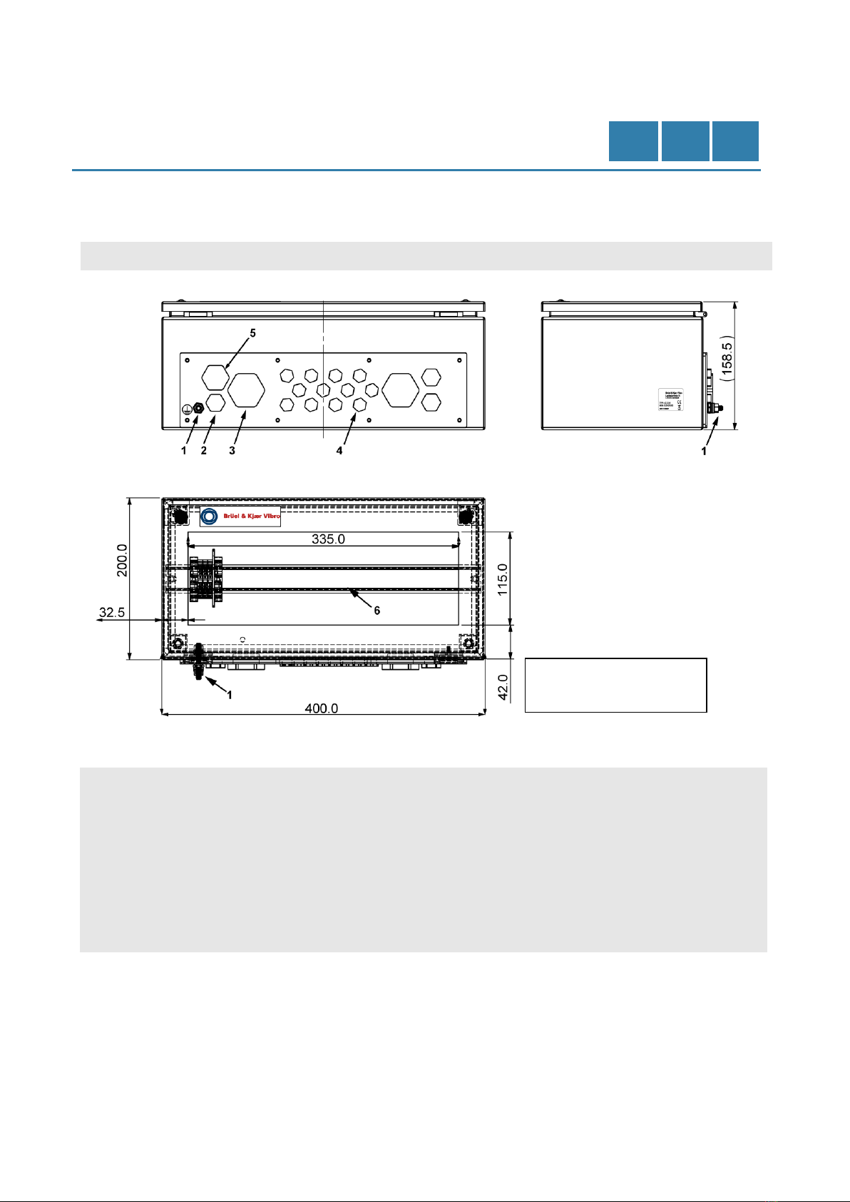
Maßzeichnung
Dimensioned drawing
Plan et dimensions
Abbildung / figure / figure 2
Bemaßung / Dimensioning / Dimensions AC-2114
Anordnungen
Kabelverschraubungen:
1. Erdungsanschluss M6
2. 3 x M16
3. 2 x M32
4. 12 x M12
5. 1 x M20 für RJ45 Anschluss
6. Hutschiene
(Tragschiene TS 35/7,5)
Threaded cable connector
configuration:
1. Grounding connection M6
2. 3 x M16
3. 2 x M32
4. 12 x M12
5. 1 x M20 for RJ45 connection
6. DIN rail
(supporting rail TS 35/7,5)
Configuration des passages de câble
filetés (selon repères numérotés) :
1. Mise à la terre M6
2. 3 x M16
3. 2 x M32
4. 12 x M12
5. 1 x M20 pour LAN RJ45
6. Rail DIN
(rail de suypport TS 35/7,5)
alle Angaben in [mm] /
all specifications in [mm] /
toutes les spécifications en [mm]

Seite/Page 4 von/of/de 16 © Brüel & Kjær Vibro ● C107834.001 / v01
Technische Änderungen vorbehalten! / Technical alterations reserved! Spécifications techniques sous réserve de modifications !
DE
EN
FR
UNRESTRICTED DOCUMENT
Zubehör (optional)
Für eine sichere Installation empfehlen
wir nur dieses Zubehör zu verwenden.
Accessories (optional)
We recommend using only these
accessories for safe installation.
Accessoires (options)
Seuls les accessoires ci-dessous sont
recommandés pour une installation
sûre.
•6x M12 Kabelverschraubung
mit Kontermutter
(Bestellcode: AC-2114/12/06).
•6x M12 Cable gland with lock
nut*
(order code: AC-2114/12/06).
•6x presse-étoupes M12 avec
contre-écrous.
(référence: AC-2114/12/06)
•4x M16 Kabelverschraubung
mit Kontermutter*
(Bestellcode: AC-2114/16/04)
•4x M16 Cable gland with lock
nut*
(order code: AC-2114/16/04)
•4x presse-étoupe M16 avec
contre-écrous.
(référence: AC-2114/16/04)
•2x M32 Kabelverschraubung
mit Kontermutter*
(Bestellcode: AC-2114/32/02)
•2x M32 Cable gland with lock
nut*
(order code: AC-2114/32/02)
•2x presse-étoupes M32 avec
contre-écrous.
(référence : AC-2114/32/02)
•4x Wandmontagehalterung
(Bestellcode:
AC-2114/WALL/04)
•4x Wall mounting bracket
(order code: AC-2114/Wall/04)
•4x équerres support de
montage mural.
(référence : AC-2114/Wall/04)
•1x M20 Kabelverschraubung
für RJ45 (Bestellcode:
AC-2114/20/01) bestehend
aus:
○M20 Dichtung für RJ45
gesplittet
○M20x1,5 Stopfbuchse
○U20.2 UNI-
Flanscheinsatz, einseitig
geschlitzt, 1x5
○U20.2 UNI-
Flanscheinsatz, einseitig
geschlitzt, 2x5
○M20x1,5 Verschluss
Mutter grau, metrisch
•1x M20 cable gland for RJ45
(order code: AC-2114/20/01)
consisting of:
○M20 cable gland splittet
for RJ45
○M20x1,5 Uni split gland
○U20.2 UNI-flange insert,
one-sided slitted, 1x5
○U20.2 UNI-flange insert,
one-sided slitted, 2x5
○M20x1,5 Lock nut, grey,
metric
•1x presse-étoupe M20 pour
câble réseau RJ45
(référence: AC-2114/20/01)
composé de:
○Presse-étoupe M20 pour
RJ45
○Presse-étoupe fendu Uni
M20x1,5
○U20.2 Insert à bride UNI,
fendu unilatéral, 1x5
○U20.2 Insert à bride UNI,
fendu unilatéral, 2x5
○Écrou de blocage
M20x1,5, gris, métrique
*
EMV Kontermutter / EMC counter nut / CEM contre-écrous

© Brüel & Kjær Vibro ● C107834.001 / v01 ●Seite/Page 5 von/of/de 16
Technische Änderungen vorbehalten! / Technical alterations reserved! / Spécifications techniques sous réserve de modifications !
AC –2114
DE
EN
FR
UNRESTRICTED DOCUMENT
Montage
Mounting
Montage
Vorbereitung
Preparation
Préparation
•Für benötigte Anschlüsse
vorhandene Blindstopfen
gegen passende Kabel-
verschraubungen aus-
tauschen (siehe optionales
Zubehör).
•Nicht an schwingenden
Maschinenteilen befestigen.
•Umgebungstemperatur am
Montageort beachten.
•Replace existing blind plugs
with suitable threaded cable
connectors for necessary
connections (see optional
accessories).
•Do not attach to vibrating parts
of the machine.
•Observe ambient temperature
at place of installation.
•Selon la connectique
souhaitée, retirez les
obturateurs adéquats pour les
remplacer par des presse-
étoupes filetés (voir liste des
accessoires optionnels).
•Ne jamais rien fixer aux pièces
mobiles de la machine.
•Vérifier la température au lieu
d’implantation.
Abbildung / figure / figure 3
Bohrplan / drilling plan / Plan de perçage AC-2114
Optionen
Options
Options
1. Montage mit Befestigungs-
schrauben.
2. Montage mit Wandhalter
(optional).
1. Mounting the fastening
screws.
2. Mounting the wall bracket
(optional).
1. Montage avec des vis de
fixation.
2. Montage des équerres de
support mural (optionnelles).
alle Angaben in [mm] /
all specifications in [mm] /
toutes les spécifications en [mm]

Seite/Page 6 von/of/de 16 © Brüel & Kjær Vibro ● C107834.001 / v01
Technische Änderungen vorbehalten! / Technical alterations reserved! Spécifications techniques sous réserve de modifications !
DE
EN
FR
UNRESTRICTED DOCUMENT
1. Montage mit
Befestigungsschrauben
1. Mounting the fastening
screws
1. Montage des vis de fixation
•Die mitgelieferten Befesti-
gungsschrauben sind aus-
schließlich für eine Montage an
Metallwänden vorgesehen.
•Die nachfolgenden
Anweisungen für alle vier (4)
Befestigungslöcher
durchführen.
•Loch mit Ø 9 mm bohren.
Bohrplan beachten, siehe
Abbildung 3.
•Die Bohrung soll entgratet und
gereinigt werden.
•Befestigungsschraube und
Mutter mit
Schraubensicherung
(LOCTITE 243 mittelfest oder
LOCTITE 270 hochfest)
versehen.
•Befestigungsschraube
rückseitig durch Metallwand
führen. Die Dichtscheibe(n) auf
das Schraubengewinde
aufstecken, so dass sich die
Dichtscheibe(n) im montierten
Zustand zwischen Metallwand
und der Unterseite des
Schutzgehäuses befindet.
Dann das Schutzgehäuse auf
den Gewindebolzen aufsetzen
und von innen mit der
gezahnten Kontaktscheibe und
der Mutter festschrauben. Die
Kontaktscheibe muss sich im
montierten Zustand unter der
Mutter befinden. Abbildung 4
zeigt diese Art der Montage
(mit optionalen Wandhalter).
Alternativ kann das Gehäuse
auch so montiert werden, dass
der Schraubenkopf von innen
durch die Bohrungen im
Gehäuse geführt wird und das
Gehäuse mit der Mutter auf
der Montagewand
festgeschraubt wird.
Die Position der Dicht- und der
gezahnten Kontaktscheibe
muss auch bei dieser Variante,
wie oben beschrieben und in
Abbildung 4 dargestellt,
beibehalten werden!
•The included fastening screws
are only intended for use in
mounting on metal walls.
•Be sure to follow these
instructions for all four (4)
fastening holes.
•Drill a hole with Ø 9 mm.
Adhere to the drilling plan
shown in Figure 3.
•The holes should be deburred
and cleaned.
•Put threadlocker (LOCTITE
243 medium-strength or
LOCTITE 270 high-strength)
on the fastening screws and
nuts.
•Push the fastening screw
through the back of the metal
wall. Push the sealing disc(s)
onto the screw thread so the
sealing disc(s) is located
between the metal wall and the
bottom of the protective
housing when installed. Then,
place the protective housing
onto the stud bolt and screw it
tight from inside with the
toothed contact disc and the
nut. The contact disc must be
located underneath the nut
when installed. Figure 4 shows
this type of installation (with
optional wall bracket).
Alternatively, the housing can
also be mounted such that the
screw head is pushed through
the holes from the inside of the
housing and the housing is
screwed tight with the nut on
the wall it is installed on.
For this type of installation, the
seal and toothed contact disc
must be in the same position
specified above and shown in
Figure 4!
•Les vis de fixation fournies
sont uniquement destinées au
montage sur paroie métallique.
•Assurez-vous de respecter
cette consigne pour les quatre
(4) trous de fixation.
•Percez un trou de Ø 9 mm.
Respectez le plan de perçage
illustré à la figure 3.
•Chaque trou doit être ébavuré
et nettoyé.
•Mettre du frein filet (LOCTITE
243 résistance moyenne ou
haute LOCTITE 270) sur les
vis et écrous de fixation.
•Poussez la vis de fixation à
travers la paroi métallique
arrière. Glissez chaque
rondelle d'étanchéité le long du
filetage de la vis de sorte que
la rondelle se trouve entre la
paroi métallique et le fond du
boîtier de protection une fois
installée. Ensuite, placez le
boîtier de protection sur le
goujon dépassant et vissez-le
fermement de l'intérieur avec
la rondelle frein dentée et
l'écrou. La rondelle frein doit
être située sous l'écrou une
fois installé. La figure 4 montre
cette fixation (avec option de
support mural).
Alternativement, le boîtier peut
être monté de telle sorte que la
tête de vis est poussée dans
les trous depuis l'intérieur du
boîtier, puis le boîtier est vissé
fermement avec l'écrou de
l’autre côté de la paroi.
Pour ce choix d'installation, les
rondelles d’étanchéité et frein
doivent être respectivement
dans la même position
spécifiée ci-avant et illustrée à
la figure 4 !
© Brüel & Kjær Vibro ● C107834.001 / v01 ●Seite/Page 7 von/of/de 16
Technische Änderungen vorbehalten! / Technical alterations reserved! / Spécifications techniques sous réserve de modifications !
AC –2114
DE
EN
FR
UNRESTRICTED DOCUMENT
2. Montage mit Wandhalter
(optional)
2. Mounting the wall bracket
(optional)
2. Montage du support mural
(optionnel) sur boîter
•Wandhalter werden ohne
Wandschrauben und Dübel
geliefert.
•Wall brackets are provided
without wall screws and
dowels.
•Les supports muraux sont
fournis sans vis ni chevilles.
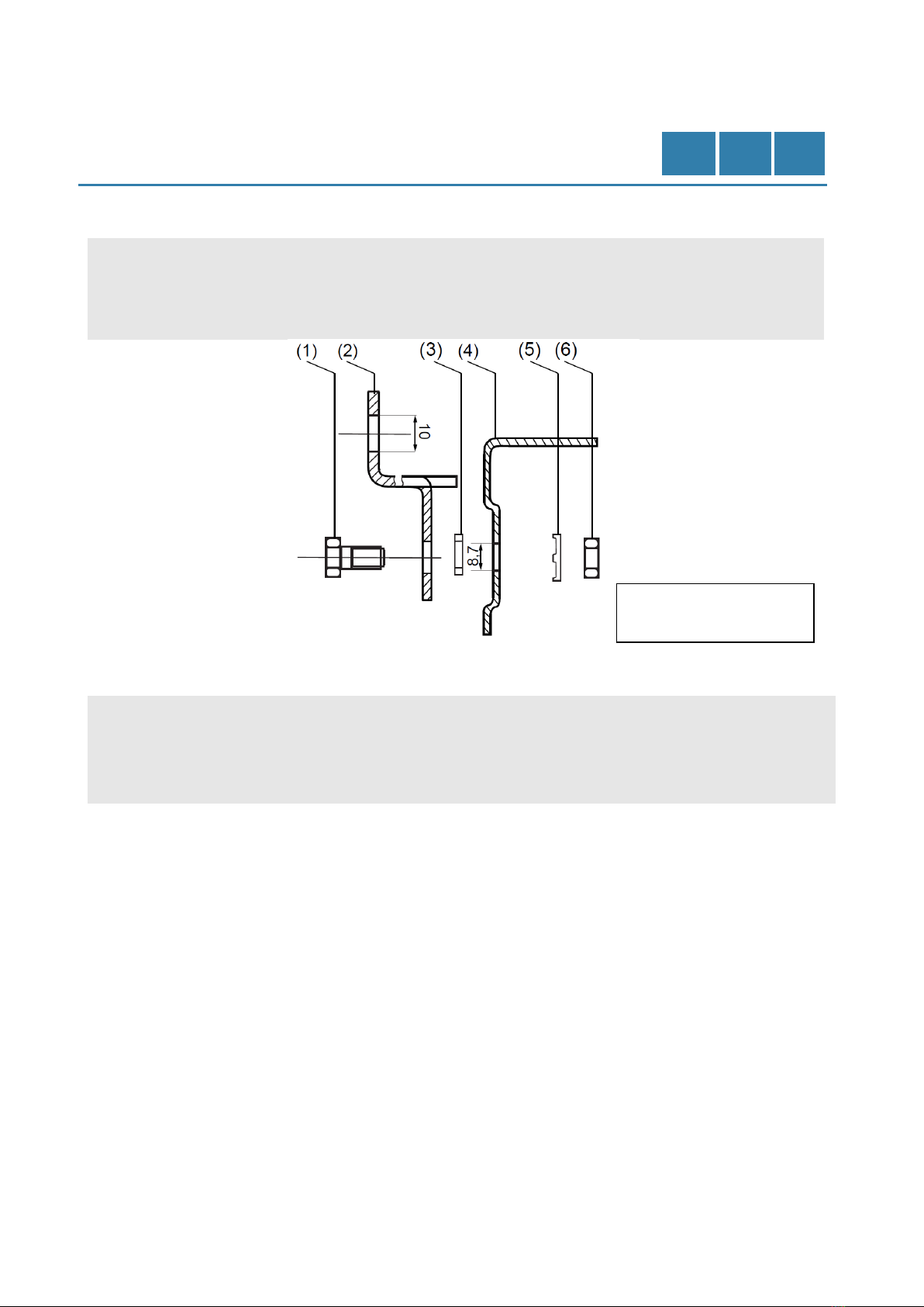
Abbildung / figure / figure 4
Montage Wandhalter mit Gehäuse (Schema) / Installation of wall bracket with housing (schematic) / Installation du
support mural avec boîtier (Schéma)
•Befestigungsschraube und
Mutter mit Schrauben-
sicherung (LOCTITE 243
mittelfest oder LOCTITE 270
hochfest) versehen.
•Put threadlocker (LOCTITE
243 medium-strength or
LOCTITE 270 high-strength)
on the fastening screws and
nuts.
•Mettre un frein filet (LOCTITE
243 résistance moyenne ou
LOCTITE 270 haute) sur les
vis et écrous de fixation.
•Befestigungsschraube (1)
rückseitig durch Wandhalter
(2) durchführen. Die
Dichtscheibe(n) (3) auf das
Schraubengewinde
aufstecken, so dass sich die
Dichtscheibe(n) im montierten
Zustand zwischen Wandhalter
(2) und der Unterseite des
Schutzgehäuses (4) befindet.
•Mit gezahnter Kontaktscheibe
(5) und der Mutter (6) im
Gehäuse (4) befestigen
(siehe Abbildung 4).
•Push the fastening screw (1)
through the back of the wall
bracket (2). Push the seal
disc(s) (3) onto the screw
thread so the seal disc(s) are
located between the wall
bracket (2) and the bottom of
the protective housing (4).
•Fasten in the housing (4) with
the toothed contact disc (5)
and the nut (6) (see Figure 4).
•Poussez la vis de fixation (1) à
travers l'arrière du support
mural (2). Poussez chaque
rondelle d'étanchéité (3) sur le
filetage de la vis de sorte que
chacune se trouve entre le
support mural (2) et le fond du
boîtier de protection (4).
•Depuis l’intérieur du boîtier (4),
fixez avec la rondelle frein
dentée (5) avec l'écrou (6),
selon la figure 4.
alle Angaben in [mm] /
all specifications in [mm] /
toutes les spécifications en [mm]

Seite/Page 8 von/of/de 16 © Brüel & Kjær Vibro ● C107834.001 / v01
Technische Änderungen vorbehalten! / Technical alterations reserved! Spécifications techniques sous réserve de modifications !
DE
EN
FR
UNRESTRICTED DOCUMENT
Abbildung / figure / figure 5
Bohrplan Wandhalter / Drilling plan wall bracket / Plan de perçage du support mural
•Die nachfolgenden
Anweisungen für alle
4 Befestigungslöcher
durchführen:
Steinwand
•Loch Ø 10 mm bohren.
Bohrplan beachten
(siehe Abbildung 5).
•Loch reinigen und 10er Dübel
einführen.
•Wandschraube
(Ø 8 mm) durch die
Wandhalter führen und in die,
mit Dübeln versehenen,
Löcher einschrauben.
•Be sure to follow these
instructions for all 4 fastening
holes:
Stone or Brick Wall
•Drill a Ø 10 mm hole. Adhere
to the drilling plan (shown in
Figure 5).
•Clean the hole and insert the
10 mm diameter dowel.
•Push the wall screw (Ø 8 mm)
through the wall bracket and
screw into the holes equipped
with dowels.
•Assurez-vous de suivre ces
instructions pour les 4 trous de
fixation :
Mur en pierre ou de brique
•Percez un trou Ø 10 mm.
Respectez le plan de perçage
(illustré en figure 5).
•Nettoyez le trou et insérez une
cheville de 10 mm de
diamètre.
•Poussez chaque vis (Ø 8 mm)
à travers le support mural et
vissez dans les trous de
chevilles.
Metallwand
•Loch Ø 9 mm bohren.
Bohrplan beachten
(siehe Abbildung 5).
•Die Bohrung soll entgratet
und gereinigt werden.
•Wandschraube (M8) durch
Metallwand und Wandhalter
führen. Mit der Mutter
befestigen und mit
Schraubenssicherung
(LOCTITE 243 mittelfest oder
LOCTITE 270 hochfest)
versehen.
Metal Wall
•Drill a Ø 9 mm hole. Adhere to
the drilling plan (shown in
Figure 5).
•The hole should be deburred
and cleaned.
•Push the wall screw (M8)
through the metal wall and wall
bracket. Fasten it with the nut
and apply threadlocker
(LOCTITE 243 medium-
strength or LOCTITE 270 high-
strength).
Paroie métallique
•Percez un trou Ø 9 mm.
Respectez le plan de perçage
(voir figure 5).
•Ebavurer et nettoyer chaque
trou.
•Poussez chaque vis (M8) à
travers la paroie métallique et
le support. Fixez-la avec
l'écrou et appliquez du frein
filet (LOCTITE 243 résistance
moyenne ou LOCTITE 270
haute).
alle Angaben in [mm] /
all specifications in [mm] /
toutes les spécifications en [mm]

© Brüel & Kjær Vibro ● C107834.001 / v01 ●Seite/Page 9 von/of/de 16
Technische Änderungen vorbehalten! / Technical alterations reserved! / Spécifications techniques sous réserve de modifications !
AC –2114
DE
EN
FR
UNRESTRICTED DOCUMENT
Erdungskonzept (PE)
Grounding concept (PE)
Recommandations de mise
à la terre (PE)
•Bei der Montage des
Schutzgehäuse AC-2114 auf
einer (elektrisch leitenden)
Montageplatte, muss diese
ebenfalls geerdet sein.
•When the protective housing
AC-2114 is mounted on a
(electrically conductive)
mounting plate, it must also be
grounded.
•Lorsque le coffret de protection
AC-2114 est monté sur une
plaque de montage conductrice
(d'électricité), il doit également
être mis à la terre.
Abbildung / figure / figure 6
Anschlussblock / Terminal block / Borniers de jonction

Seite/Page 10 von/of/de 16 © Brüel & Kjær Vibro ● C107834.001 / v01
Technische Änderungen vorbehalten! / Technical alterations reserved! Spécifications techniques sous réserve de modifications !
DE
EN
FR
UNRESTRICTED DOCUMENT
Einbaubeispiele
Montage VC-18xx
Installation examples
Mounting VC-18xx
Exemples de montage
avec VC-18xx
Hinweise:
Hints:
Conseils:
•Die Montage darf nur im
spannungslosen Zustand
durchgeführt werden!
•Es ist die Betriebsanleitung
des Netzteils AC-4111 zu
beachten.
•The Installation may only be
undertaken in the idle state!
•Observe the operating
instructions for the power
supply AC-4111.
•L´installation ne peut être
effectuée que hors tension !
•Respectez le mode d'emploi
de l'alimentation AC-4111.
•Das Gerät darf nur an der
Wand montiert betrieben
werden und muss so
positioniert werden, dass die
Kabelverschraubungen unten
liegen.
•Aufgrund der eingeschränkten
Luftzirkulation kommt es zu
einer Reduzierung des
zulässigen Arbeitstemperatur-
bereiches auf -10 °C … +40 °C
gegenüber den Angaben in
den technischen Daten zu
VC-18xx.
•In das Schutzgehäuse
AC-2114 können bis zu drei
Überwachungselektroniken
vom Typ VC-1850, VC-1860,
oder VC-1870 mit jeweils
einem Netzteil AC-4111 und
einem Relais-Modul VC-1801
eingebaut werden.
•Als Schnittstelle zur
Kommunikation kann
zusätzlich ein Modul vom Typ
VC-1803 oder VC-1804
eingebaut werden.
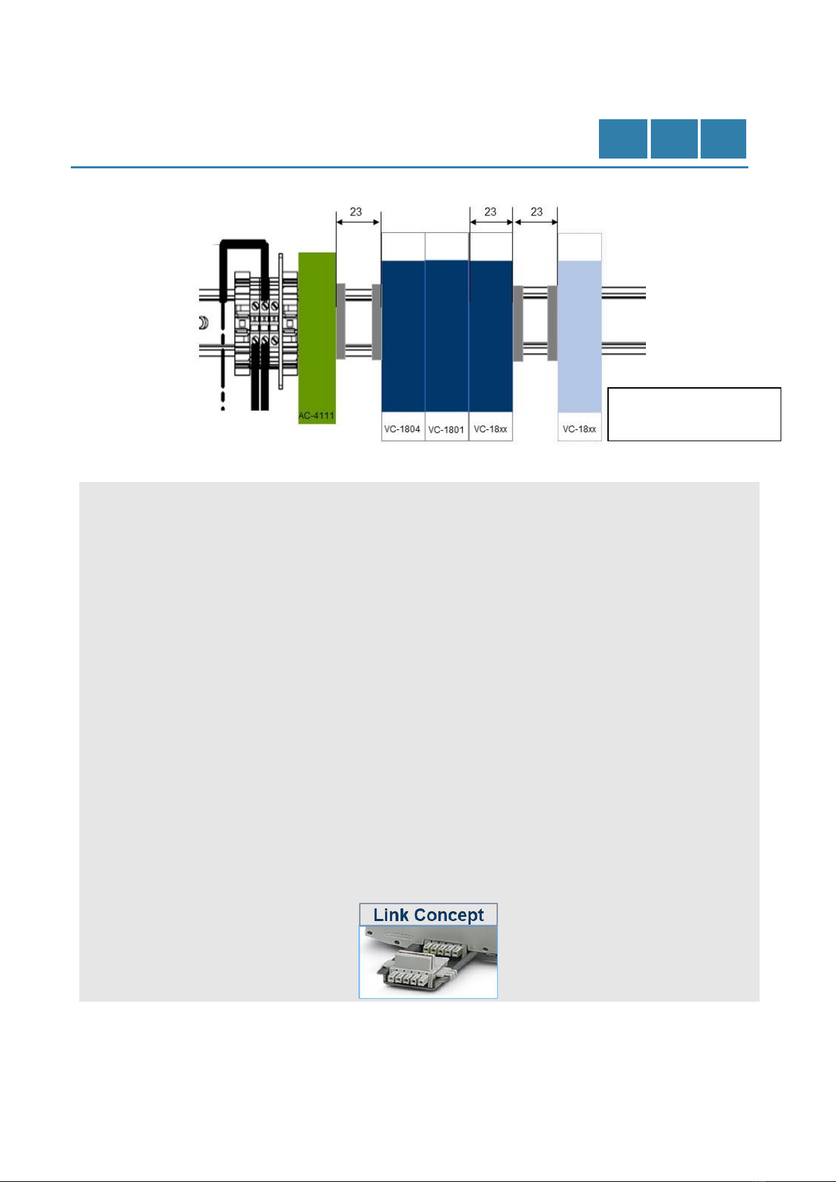
•Bei der Platzierung der Module
auf der Hutschine ist dafür zu
sorgen, das mindestens
einseitig zu jedem
Überwachungsmonitor vom
Typ VC-1850, VC-1860, oder
VC-1870 ein Freiraum von
23 mm (eine Modulbreite)
eingehalten wird!
•The device can only be
operated while mounted on the
wall and must be positioned so
the threaded cable connectors
are facing downwards.
•Due to the restricted air
circulation, the permissible
working temperature range is
reduced to -10 °C … +40 °C
compared to the technical data
in the specification of VC-18xx.
•In the protective housing
AC-2114, up to three
monitoring electronics of the
type VC-1850, VC-1860, or
VC-1870, each with an
AC-4111 power supply unit
and a VC-1801 relay module,
can be installed.
•A VC-1803 or VC-1804 module
can also be installed as an
interface for communication.
•When placing the modules on
the DIN rail, it must be ensured
that at least one side of each
monitor type VC-1850,
VC-1860, or VC-1870 has a
clearance of minimum 23 mm
(one module width)!
•Le coffret doit être monté sur le
mur et positionné de sorte que
les presse-étoupes de câbles
soient orientés vers le bas.
•En raison de la circulation d'air
restreinte, la plage autorisée
de température de travail est
réduite de -10 °C à +40 °C, par
rapport aux spécifications
techniques des VC-18xx.
•Dans le coffret AC-2114,
jusqu'à trois électroniques de
surveillance de type VC-1850,
VC-1860 ou VC-1870 peuvent
être installés, chacune avec un
bloc d'alimentation AC-4111 et
un module de relais VC-1801.
•Un module VC-1803 ou
VC-1804 peut également être
installé comme interface de
communication.
•Lors du placement des
modules sur le rail DIN, il faut
s'assurer qu'au moins un côté
de chaque moniteur de type
VC-1850, VC-1860 ou
VC-1870 a un dégagement
d'au moins 23 mm (une largeur
de module) !
© Brüel & Kjær Vibro ● C107834.001 / v01 ●Seite/Page 11 von/of/de 16
Technische Änderungen vorbehalten! / Technical alterations reserved! / Spécifications techniques sous réserve de modifications !
AC –2114
DE
EN
FR
UNRESTRICTED DOCUMENT
Abbildung / figure / figure 7
Montageaufbau VC-18xx / Installation VC-18xx / Installation de VC-18xx
Vorbereitung
Preparation
Préparation
•Für den elektrischen Anschluss
ist es sinnvoll, die
Phönixstecker zunächst von
den VC-18xx Modulen zu
trennen.
•Für das Entfernen der VC-18xx
Module von der Hutschiene,
den Clip mit einem Schlitz-
Schraubendreher betätigen.
•Die Nummerierung auf den
Phönixsteckern ist für den
späteren elektrischen
Anschluss der VC-18xx Geräte
zu beachten.
•Entsprechende Verdrahtungen
mit den Phönixsteckern
herstellen. Die Kabelschirme
sorgfältig in den
Kabelverschraubungen
auflegen.
•Verbinden Sie die Module über
die unteren "Link-Concept" -
Anschlüsse.
•In order to connect the
electronics, it is best to first
disconnect the Phoenix
connectors from the VC-18xx
modules.
•Operate the clip using a slotted
screwdriver in order to remove
the VC-18xx modules from the
DIN rail.
•The numbering on the Phoenix
connectors must be observed
when connecting the VC-18xx
devices later.
•Configure the wiring with the
Phoenix connectors
accordingly. Carefully apply
the cable shields to the
threaded cable connectors.
•Connect the modules together
using the lower "Link-Concept"
connectors.
•Pour connecter des voies, il est
préférable de déconnecter
d'abord les connecteurs
Phoenix des modules VC-18xx.
•Actionnez le clip à l'aide d'un
tournevis plat pour retirer un
module VC-18xx du rail DIN.
La numérotation des connecteurs
Phoenix doit être respectée lors
de la remise en place sur
l’appareil VC-18xx.
•Adapter le câblage sur les
connecteurs Phoenix en
fonction du schéma. Connectez
soigneusement les blindages
de câble sur les presse-
étoupes filetés.
•Raccorder les modules entre
eux à l’aide des connecteurs
inférieurs « Link-Concept ».
alle Angaben in [mm] /
all specifications in [mm] /
toutes les spécifications en [mm]
Seite/Page 12 von/of/de 16 © Brüel & Kjær Vibro ● C107834.001 / v01
Technische Änderungen vorbehalten! / Technical alterations reserved! Spécifications techniques sous réserve de modifications !
DE
EN
FR
UNRESTRICTED DOCUMENT
Einbau in das Schutzgehäuse
Installation in the protective
housing
Installation dans le coffret de
protection
Die Verbindung zwischen dem
VC-18xx und dem eingebauten
Netzteil AC-4111 herstellen.
•Alle oberen Phönixstecker mit
dem VC-18xx verbinden.
Nummerierung der
Phönixstecker ist dringend zu
beachten.
•Bei Verwendung der
mitgelieferten Klemmen, muss
die Versorgungsspannung
vorher abgeschaltet sein. Dann
das VC-18xx in die Hutschiene
einrasten.
•Verdrahtung vor dem
Einschalten überprüfen.
Module auf festen Sitz auf der
Hutschiene prüfen.
Establish a connection between the
VC-18xx and the installed power
supply AC-4111.
•Connect all top Phoenix
connectors with the VC-18xx.
It is important to observe the
numbering of the Phoenix plug.
•When using the provided
terminals, be sure to shut off
the power supply beforehand.
Then snap the VC-18xx into
the DIN rail.
•Check the wiring before turning
it on. Check that the modules
are securely fastened to the
DIN rail.
Connecter le module alimentation
AC-4111 au VC-1850/60/70 installé.
•Connectez tous les bornes
Phoenix supérieurs au
VC-18xx. Il est important de
respecter la numérotation de la
prise Phoenix.
•Assurez-vous de couper
l'alimentation électrique au
préalable, et utilisez les bornes
fournies. Puis enclenchez le
VC-18xx dans le rail DIN.
•Vérifiez l’ensemble du câblage
avant de mettre sous tension.
Vérifiez que les modules sont
solidement fixés au rail DIN.
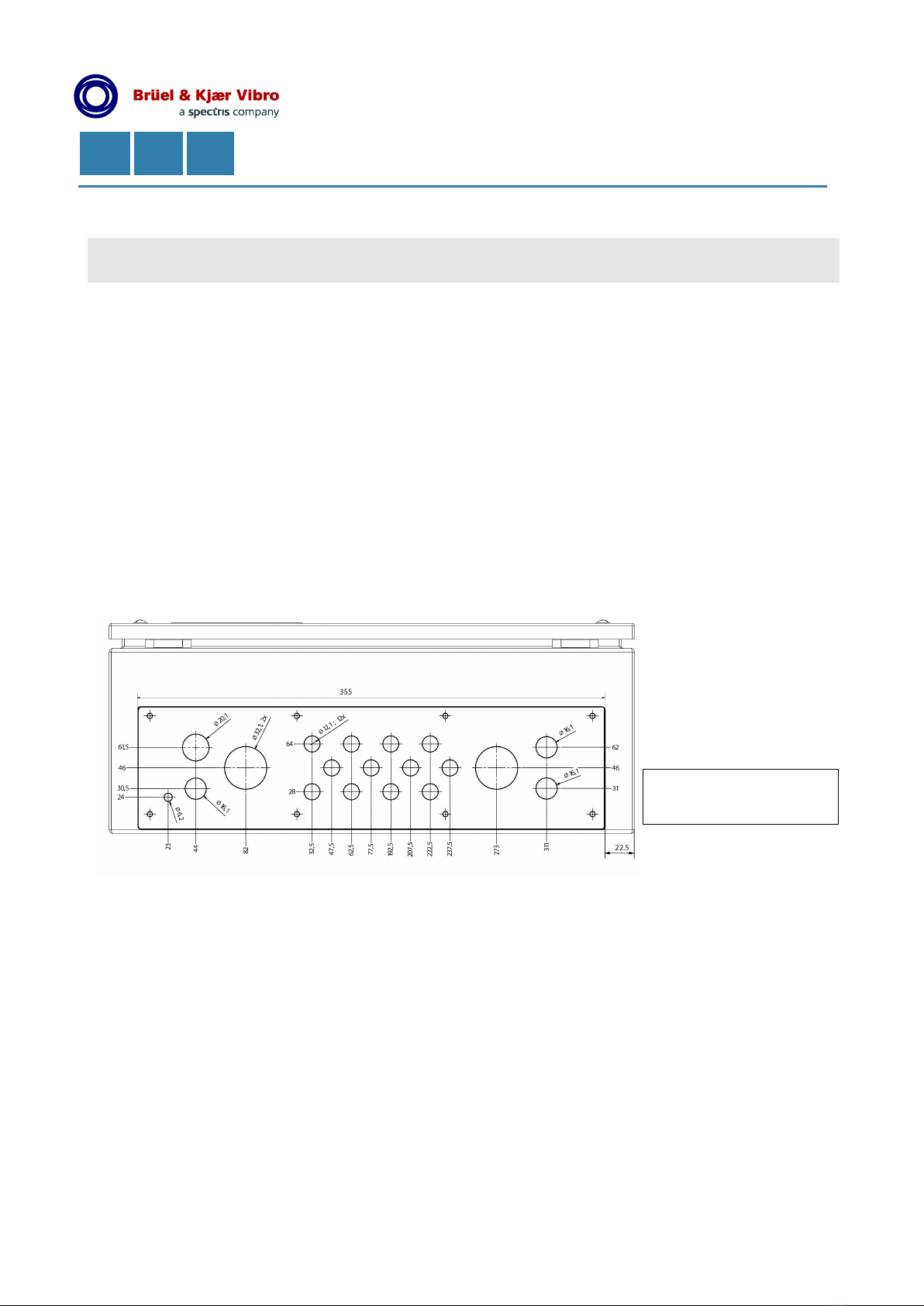
Abbildung / figure / figure 8
Flanschplatte / Flange plate / Plaque à brides
alle Angaben in [mm] /
all specifications in [mm] /
toutes les spécifications en [mm]
© Brüel & Kjær Vibro ● C107834.001 / v01 ●Seite/Page 13 von/of/de 16
Technische Änderungen vorbehalten! / Technical alterations reserved! / Spécifications techniques sous réserve de modifications !
AC –2114
DE
EN
FR
UNRESTRICTED DOCUMENT
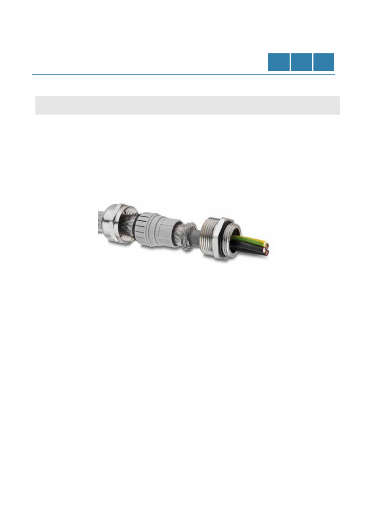
Kabelverlegung mit
Stahlschutzschlauch
Wire Configuration with Steel
Protective Conduit
Configuration avec gaine
métallique de protection
•Bei Kabelverlegung mit
Stahlschutzschlauch muss
dieser unmittelbar vor der
Kabelverschraubung
abgefangen werden.
•Zur Erreichung einer optimalen
Schirmwirkung ist der
Kabelschirm an den
Kabelverschraubungen
aufzulegen.
•If the cables are laid in a steel
protective conduit, the conduit
must be intercepted directly
before the cable gland.
•For achieving an optimum
shield effect, the cable screen
as to be connected to the
conduit thread.
•Si le câble est protégé dans
une gaine métallique, celle-ci
doit être coupée et directement
reliée dans le presse-étoupe.
•Pour une efficacité optimale du
blindage, la tresse doit être en
contact avec le fond du presse-
étoupe vers le boitier.
Abbildung / figure / figure 9
Auflegen des Kabelschirms / Connecting the cable screen / Raccordement du blindage
•Auflegen des Kabelschirms in
der Kabelverschraubung (M12,
M16, M32). Angaben des
Herstellers beachten.
○M12: Ø 3,0 –6,5 mm
○M16: Ø 5,5 –10,0 mm
○M32: Ø 15,5 –21,0 mm
•Das Gehäuse muss an der
äußeren Erdanschluss-
schraube niederohmig
geerdet werden (siehe
Abbildung 2, Nr.1).
•Beim Schließen des Deckels
auf Dichtheit der
Gehäusedichtung achten.
•Klemmbereich Anschluss-
klemmen (grün/gelb bzw. PE)
○Für starres Kabel:
0,08 mm² - 6 mm²,
AWG: 28 - 10
○Für flexibles Kabel:
0,08 mm² - 4 mm²,
AWG: 28 - 12
•Connecting the cable screen to
the conduit thread (M12, M16,
M32). Observe the
manufacturer’s instructions.
○M12: Ø 3,0 –6,5 mm
○M16: Ø 5,5 –10,0 mm
○M32: Ø 15,5 –21,0 mm
•The housing has to be
connected to the with low
resistance to the grounding
screw (see figure 2, no.1).
•When closing the fitting take
care of the tightness of the seal
lip.
•Clamping range terminals
(green / yellow or PE)
○For rigid cables:
0.08 mm² - 6 mm²,
AWG: 28 - 10
○For flexible cable:
0.08 mm² - 4 mm²,
AWG: 28 - 12
•Raccordement du blindage du
câble dans le presse-étoupe
(M12, M16, M32). Respectez
les instructions du fabricant.
○M12: Ø 3,0 –6,5 mm
○M16: Ø 5,5 –10,0 mm
○M32: Ø 15,5 –21,0 mm
•Le boîtier doit être connecté
avec une faible impédance à la
vis de mise à la terre (voir
figure 2, n° 1).
•S'assurer de l'étanchéité du
joint à lèvre lors de la
fermeture du couvercle.
•Gamme de bornes de serrage
(vert / jaune ou PE)
○Pour câble rigide :
0,08 mm² - 6 mm²,
AWG: 28 - 10
○Pour câble souple :
0,08 mm² - 4 mm²,
AWG: 28 - 12
Seite/Page 14 von/of/de 16 © Brüel & Kjær Vibro ● C107834.001 / v01
Technische Änderungen vorbehalten! / Technical alterations reserved! Spécifications techniques sous réserve de modifications !
DE
EN
FR
UNRESTRICTED DOCUMENT
Demontage und
Entsorgung
Disassembly and
Disposal
Dépose et Élimination
•Die Demontage darf nur im
spannungslosen Zustand
durchgeführt werden!
•The assembly may only be
undertaken in the idle state!
•Le démontage ne peut
s’effectuer que hors tension !
•Dieses Produkt unterliegt dem
Elektro- und Elektronikgeräte-
Abfallgesetz.
•Werfen Sie das Gerät nicht in
den Hausmüll und beachten
Sie die örtlichen Vorschriften
zur Abfallbeseitigung. Sie
können das Gerat auch an
Brüel & Kjaer Vibro -
Leydheckerstrase 10 -
64293 Darmstadt -
Deutschland zurücksenden.
•WEEE-Reg.-Nr. DE 69572330
•The driver is subject to the
Waste Disposal Act for
Electrical and Electronic
Equipment.
•Do not dispose of the device in
the regular household waste
and observe local waste
disposal regulations. You may
also return the device to
Brüel & Kjaer Vibro -
Leydheckerstraße 10 -
64293 Darmstadt - Germany.
•WEEE Reg. No. DE 69572330
•Les composants internes sont
soumis à la règlementation sur
les déchets électriques et
électroniques.
•Ne pas jeter l'équipement dans
les ordures ménagères et
respecter les dispositions
locales d'élimination des
déchets. L'appareil peut aussi
être renvoyé à Brüel & Kjaer
Vibro - Leydheckerstraße 10 -
64293 Darmstadt –Allemagne.
•Nº d'enregistrement WEEE n°
DE 69572330

© Brüel & Kjær Vibro ● C107834.001 / v01 ●Seite/Page 15 von/of/de 16
Technische Änderungen vorbehalten! / Technical alterations reserved! / Spécifications techniques sous réserve de modifications !
AC –2114
DE
EN
FR
UNRESTRICTED DOCUMENT
CE-Erklärung
Declaration of
conformity
Déclaration de
conformité

Kontakt/Contact
Brüel & Kjær Vibro GmbH
Leydheckerstrasse 10
64293 Darmstadt
Germany
Phone: +49 6151 428 0
Fax: +49 6151 428 1000
Brüel & Kjær Vibro A/S
Skodsborgvej 307 B
2850 Nærum
Denmark
Phone: +45 77 41 25 00
Fax: +45 45 80 29 37
BK Vibro America Inc.
1100 Mark Circle
Gardnerville NV 89410
USA
Phone: +1 (775) 552 3110
Homepage: www.bkvibro.com
AC-2114 ● C107834.001 / v01 ● © Brüel & Kjær Vibro ●
Technische Änderungen vorbehalten! / Technical alterations reserved! / Spécifications techniques sous réserve de
modifications !
Table of contents
Popular Enclosure manuals by other brands


Advantech
Advantech CompactPCI MIC-3041 Startup manual

Kingston Technology
Kingston Technology StorCase Technology Data Silo DS560 user guide

thuba
thuba PS 830 manual

WilTec
WilTec Fudajo 62397 Operation manual

RAK
RAK RAKBox-B2 installation guide

System Sensor
System Sensor B300-6 Installation and maintenance instructions