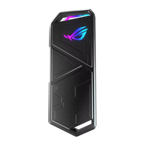
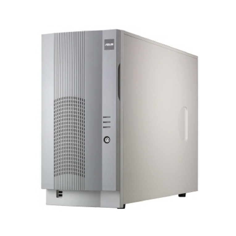
Asus ROG Z11 User manual


SE7EN

Copyright © 2020 ASUSTeK Computer Inc.
All Rights Reserved.
No part of this manual, including the products and software described in it, may be reproduced, transmitted, transcribed, stored
in a retrieval system, or translated into any language in any form or by any means, except documentation kept by the purchaser
for backup purposes, without the express written permission of ASUSTeK Computer Inc. (“ASUS”).
Product warranty or service will not be extended if: (1) the product is repaired, modified or altered, unless such repair,
modification of alteration is authorized in writing by ASUS; or (2) the serial number of the product is defaced or missing.
ASUS PROVIDES THIS MANUAL“AS IS”WITHOUT WARRANTY OF ANY KIND, EITHER EXPRESS OR IMPLIED, INCLUDING BUT NOT
LIMITED TO THE IMPLIED WARRANTIES OR CONDITIONS OF MERCHANTABILITY OR FITNESS FOR A PARTICULAR PURPOSE. IN NO
EVENT SHALL ASUS, ITS DIRECTORS, OFFICERS, EMPLOYEES OR AGENTS BE LIABLE FOR ANY INDIRECT, SPECIAL, INCIDENTAL,
OR CONSEQUENTIAL DAMAGES (INCLUDING DAMAGES FOR LOSS OF PROFITS, LOSS OF BUSINESS, LOSS OF USE OR DATA,
INTERRUPTION OF BUSINESS AND THE LIKE), EVEN IF ASUS HAS BEEN ADVISED OF THE POSSIBILITY OF SUCH DAMAGES ARISING
FROM ANY DEFECT OR ERROR IN THIS MANUAL OR PRODUCT.
SPECIFICATIONS AND INFORMATION CONTAINED IN THIS MANUAL ARE FURNISHED FOR INFORMATIONAL USE ONLY, AND
ARE SUBJECT TO CHANGE AT ANY TIME WITHOUT NOTICE, AND SHOULD NOT BE CONSTRUED AS A COMMITMENT BY ASUS.
ASUS ASSUMES NO RESPONSIBILITY OR LIABILITY FOR ANY ERRORS OR INACCURACIES THAT MAY APPEAR IN THIS MANUAL,
INCLUDING THE PRODUCTS AND SOFTWARE DESCRIBED IN IT.
Products and corporate names appearing in this manual may or may not be registered trademarks or copyrights of their
respective companies, and are used only for identification or explanation and to the owners’benefit, without intent to infringe.
Accessory Kit Contents 3
Installation Guide 4
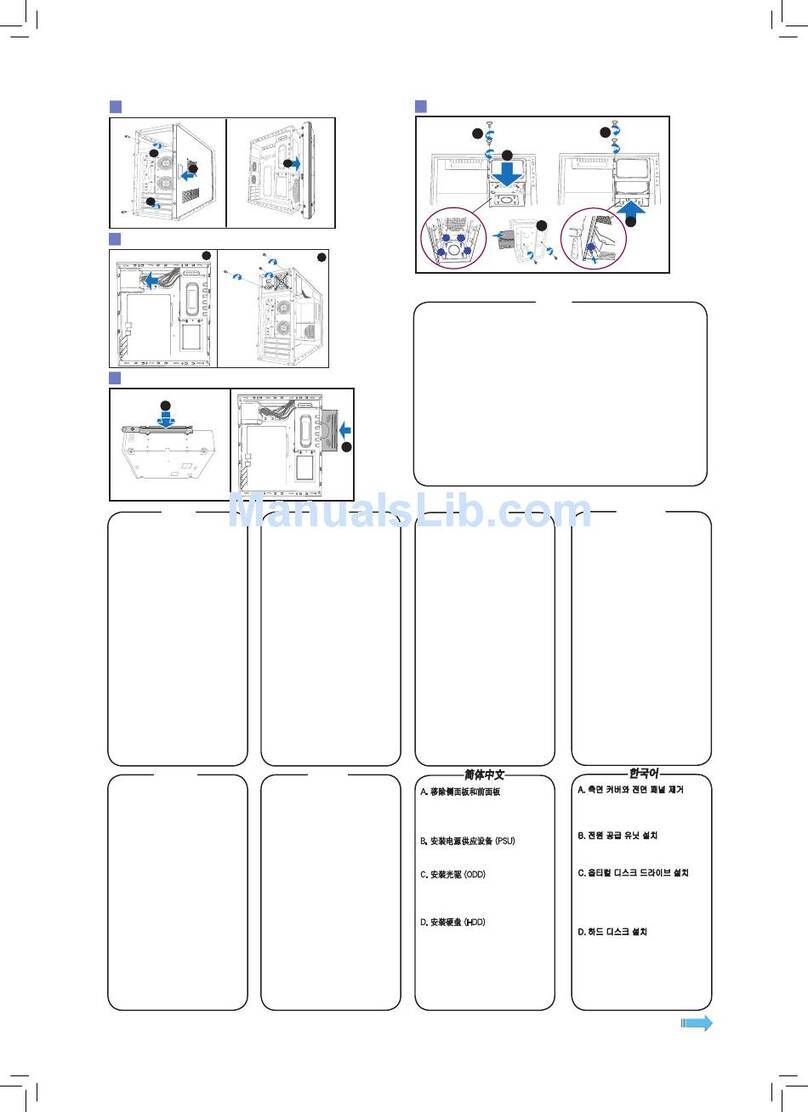
Remove the Side Panels 5
Multifunction Cover 7
Install The Power Supply Unit (PSU) 9
Install the Cooler & RAM on the Motherboard 10
Install the Motherboard Unit 11
Install the PCI-E Card 12
Attach the Front I/O Connectors 13
Sync Case Lighting With Addressable RGB Compatible Motherboards 14
Extension Hub 15
Install the 3.5"/ 2.5" Drives 16
Installation and Maintenance of the Dust Filters 18
Pump Installation 19
GPU Water Block 20
Additional Information 21
CPU Cooler Height Limitation 22
Graphics Card Limitation 23
Fan Setup Compatibility 24
Water-cooling Radiator Options 25
Optional Nameplate 28
Chassis Placement 29
Safety Information 31
Contents

Accessory
Kit Contents
配備零組件內容物 | 配备组件内容物 | Obsah sady příslušenství | Contenu du kit d’accessoires |
Verpackungsinhalt des Zubehörsatzes | Accessori contenuti nel kit | アクセサリキットの内容 | 액세서리
키트 내용물 | Zawartość zestawu akcesoriów | Conteúdo do kit de acessórios | Содержимое комплекта |
Contenido del kit de accesorios | Tillbehörssatsens innehåll | Aksesuar Kitinin İçindekiler |
A
Motherboard / 3.5” Drive / PSU Screws x14
B
2.5” Drive Screws x16
C
Graphics Card Screws x2
D
120mm Radiator Bracket Screws x4
E
Motherboard Standoff Tool x1
F
Cable Ties x10
G
PUMP Bracket x1
H
SFX PSU Bracket x1
I
120mm Radiator Bracket x1
J
90° Angle Adapter x1
K
Nameplate x1
L
Front Panel / Side Panel Screws (Backup) x4
M
Screws Driver x1

安裝指南 | 安装指南 | Instalační příručka | Guide d’installation | Installationsanleitung | Guida all’installazione | 組み立て
ガ イド | 설치 설명서 | Instrukcja instalacji | Manual de instalação | Руководство по установке | Guía de instalación |
Installationsguide | Kurulum Kılavuzu |
installation
GUIDe

5
4
3
Remove the Side Panels
移除側面板 | 移除侧面板 | Sejměte boční panely | Retirer les panneaux latéraux | Entfernen der Seitenwände | Rimuovete
i pannelli laterali | サイドパネルを取り外す | 측면 패널 제거 | Zdejmij panele boczne | Remover os painéis laterais |
Снимите боковые панели | Quite los paneles laterales | Ta bort sidopanelerna | Yan Panelleri Çıkarın |
12

6
5

7
Multifunction Cover
多功能遮蓋板 | 多功能盖板 | Multifunkční kryt | Couvercle multifonction | Multifunktionsabdeckung | Cover multifunzione
| マ ル チファンクションカ バ ー | 다기능 커버 | Pokrywa wielofunkcyjna | Tampa multifunções | Многофункциональная
крышка | Cubierta multifunción | Multifunktionshölje | Çok İşlevli Kapak |
1
2

8
3
Supports 1 x 2.5” SSD

9
Install The Power Supply Unit (PSU)
2
1
安裝電源供應器 | 安装电源供应器 | Nainstalujte zdroj napájení (PSU) | Installer le bloc d’alimentation | Installation des
Netzteils | Installate l’alimentatore (PSU) | 電源装置を取り付ける | 전원 공급장치(PSU) 설치 | Zainstaluj zasilacz (PSU) |
Instalar a fonte de alimentação (PSU) | Установите блок питания | Instalar la fuente de alimentación (PSU) | Sätt i
strömförsörjningsenheten (PSU) | Güç Kaynağı Ünitesini (PSU) Takın | (PSU)
ATX PSU:
2
1
SFX PSU:
x4
H
x1

10
Install the Cooler & RAM
on the Motherboard
安裝主機板散熱器和記憶體 | 安装主板散热器和内存 | Nainstalujte chladič a paměť RAM na základní desku | Installer le
refroidisseur et la mémoire RAM sur la carte mère | Installation des Kühlers und der RAM-Module auf das Motherboard |
Installate dissipatore e RAM sulla scheda madre | CPU、クーラー、メモリーをマザーボードに取り付ける |
메인보드에 쿨러 및 RAM 설치 | Zainstaluj element chłodzący i pamięć RAM na płycie głównej |
Instalar o dissipador e memória RAM na placa principal | Установите на материнскую
плату кулер и память | Instalar el refrigerador y la memoria RAM en la placa base |
Montera kylare och RAM på moderkortet | Soğutucu ve RAM’i Anakarta Takın |
(RAM)
1
2

11
Install the Motherboard Unit
將主機板裝入機殼 | 将主板装入机箱 | Nainstalujte základní desku | Installer la carte mère | Installation der Motherboard-
Baugruppe | Installate la scheda madre | マザーボードを取り付ける | 메인보드 유닛 설치 | Zainstaluj płytę główną |
Instalar a placa principal | Установите материнскую плату | Instalar la unidad de la placa base | Installera
moderkortsenheten | Anakart Ünitesini Takın |
x4
1
2

12
Install the PCI-E Card
x2
安裝 PCI-E 卡 | 安裝 PCI-E 卡 | Nainstalujte PCI-E kartu | Installer la carte PCI-E | Installation der PCI-E-Karte | Installate la
scheda PCI-E | 拡張カードを取り付 ける | PCI-E 카드 설치 | Zainstaluj kartę PCI-E | Instalar a placa PCI-E | Установите карту
PCI-E | Instalar la tarjeta PCI-E | Installera PCI-E-kortet | PCI-E Kartını Takın | PCI-E

13
Attach the Front I/O Connectors
連接前面板 I/O 插孔 | 连接前面板 I/O 插孔 | Připojte přední I/O konektory | Fixer les connecteurs d’E/S avants | Befestigen
der vorderen E/A-Anschlüsse | Collegate i connettori di I/O frontali | フロント I/Oコネクターを取り付ける | 전면 I/O 커넥터
연결 | Zamocuj przednie złącza We/Wy | Encaixar os conectores de E/S frontais | Подключите разъемы для передней
панели | Acoplar los conectores de E/S frontales | Anslut de främre I/O-kontakterna | Ön G/Ç Konektörlerini Takın |

14
可編程 RGB燈光與可兼容主機板同步燈光控制 | 可编程RGB灯效与可兼容主板同步灯光控制 | Synchronizovat osvětlení
skříně se základními deskami, které jsou kompatibilní s adresovatelným RGB | Synchroniser l’éclairage du châssis avec les
cartes mères compatibles RGB adressables | Synchronisieren der Gehäusebeleuchtung über ansteuerbare RGB-kompatible
Motherboards | Sincronizza l’illuminazione del case con le schede madri compatibili con l’indirizzamento RGB | アドレ サ
ブルLED対応マザーボードによるライティングの同期 | 주소 지정이 가능한 RGB를 채택한 싱크 케이스 조명 호환
메인보드 | Synchronizacja podświetlenia obudowy z płytami głównymi zgodnymi z adresowalnym podświetleniem RGB |
Sincronize a iluminação da caixa com placas principais compatíveis com RGB endereçável |
Синхронизировать подсветку корпуса с адресуемой RGB-лентой материнской платы |
Sincronizar la iluminación de la carcasa con placas base compatibles con
RGB direccionable | Hölje med synkroniserat ljus med adresserbara
RGB-kompatibla moderkort | Kasa Aydınlatmasını
Adreslenebilir RGB Uyumlu Ana Kartlarla Eşitleyin |
RGB
Sync Case Lighting With
Addressable RGB Compatible
Motherboards
Front I/O panel
Turn on Press LED button for 6 seconds
Turn off Press LED button for 6 seconds
Mode Change Press LED button for 2 seconds
Back to Default Press LED button for 4 seconds
MB Sync up with MB Lighting
Mode
Static Breathing Strobing Rainbow
Color White / Red / Orange / Yellow / Green / Blue / Cyan /
Purple / Rainbow
Default Mode: Rainbow Color: Rainbow
* MB mode only works when connecting control board to MB Addressable RGB header
* Compatible with AURA Sync

15
Extension Hub
Connect to Front I/O
ARGB header
Connect to Front
I/O PCBA USB 2.0
SATA Power:
Connect to PSU
USB 2.0:
Dedicated USB connection for the ROG Ryujin 240mm AIO Cooler OLED
or other OLED integrated AIO Coolers.
NOTE: This connector is for the AIO Cooler OLED and should not be connected to the Front
I/O USB 2.0 connector.
Connect to ARGB Fan / LED Strip
Connect to 4-pin PWM fan
Connect to
motherboard
4-pin PWM
fan header
SATA Power:
Connect to PSU
擴展集線器 | 扩展集线器 | Prostor pro zapojení | Hub d’extension | Erweiterter Hub | Hub di estensione | 拡張ハブ | 확장
허브 | Hub rozszerzeń | Hub de extensão | Концентратор | Concentrador de extensión | Anslutningshubb | Genişletme
Göbeği |
Front I/O panel
Connect to MB
ARGB header
(AURA Sync)
* The maximum output of PWM Fan connector is 2.6A.
* The maximum output of LED Strip connector is 2.6A.

16
Install the 3.5"/ 2.5" Drives
安裝 3.5 / 2.5 吋硬碟 | 安裝 3.5 / 2.5 英寸硬盘 | Nainstalujte 3,5”/2,5”jednotky | Installer les lecteurs 3.5”/2.5” | Installation
der 3,5-Zoll-/2,5-Zoll-Laufwerke | Installate i drive 3.5”/2.5”| 3.5インチ/2.5インチ ドライブを取り付 ける | 3.5”/2.5” 드라이브
설치 | Zainstaluj napędy 3,5”/2,5”| Instalar as unidades de 3,5”/2,5” | Установите 3,5/2,5-дюймовые диски | Instalar las
unidades de 3,5”/2,5”| Installera 3,5”/2,5”-enheterna | 3,5”/2,5” Sürücüleri Takın | 2.5/3.5
x4 x8
1
2
or
H:3.5” Drive
S:2.5” Drives
3.5” Drive 2.5” Drive

17
3
4
2.5” Drive
2.5” Drive

18
Installation and Maintenance of
the Dust Filters
防塵網安裝及保養 | 防尘网安装及保养 | Instalace a údržba prachových filtrů | Installation et entretien des filtres à
poussière | Installation und Wartung der Staubfilter | Installazione e manutenzione dei filtri antipolvere | ダストフィルター
を取り付ける | 먼지 필터의 설치 및 유지보수 | Instalacja i konserwacja filtrów antykurzowych | Instalação e manutenção
dos filtros de pó | Установка и обслуживание пылевых фильтров | Instalación y mantenimiento de los filtros de polvo |
Installation och underhåll av dammfiltren | Toz Filtrelerinin Kurulumu ve Bakımı |
This manual suits for next models
1
Table of contents
Other Asus Enclosure manuals

Asus
Asus USB 3.1 ENCLOSURE User manual

Asus
Asus ROG STRIX ARION User manual

Asus
Asus TS-8A User manual

Asus
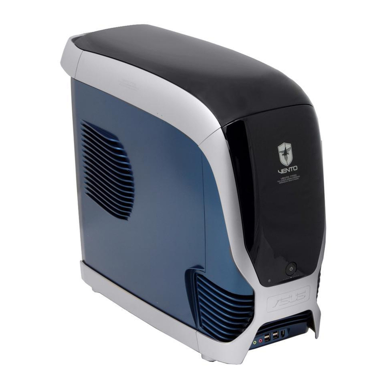
Asus Vento 7700 User manual

Asus
Asus TS-63 User manual

Asus
Asus 5U Tower Chassis Kit AK34 User manual

Asus
Asus 3600 - VENTO Mid Tower User manual

Asus
Asus Vintage2-AE1 User manual

Asus
Asus 5U Tower Chassis Kit AK35 User manual

Asus
Asus TUF Gaming GT301 User manual
Popular Enclosure manuals by other brands

Primo Water
Primo Water XL 190 Assembly instruction

Thermaltake
Thermaltake Siver River Duo user manual

ETERNAL RIVAL
ETERNAL RIVAL Hybrid X manual

Moog
Moog IGDW75C1N Installation and operation instructions

RaidSonic Technology
RaidSonic Technology Icy Box IB-1824ML-C31 manual

Taurus
Taurus Super-S Combo user manual