manuals.online logo
Brands
  1. Home
  2. •
  3. Brands
  4. •
  5. CommScope
  6. •
  7. Enclosure
  8. •
  9. CommScope BUDI-M User manual

CommScope BUDI-M User manual

Other CommScope Enclosure manuals
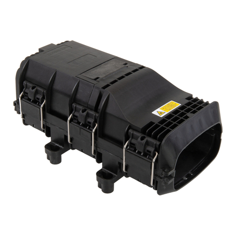
CommScope Mini-OTE 300 Tap User manual

CommScope

CommScope Mini-OTE 300 Tap User manual

CommScope FDH 3000 User manual

CommScope

CommScope FDH 3000 User manual

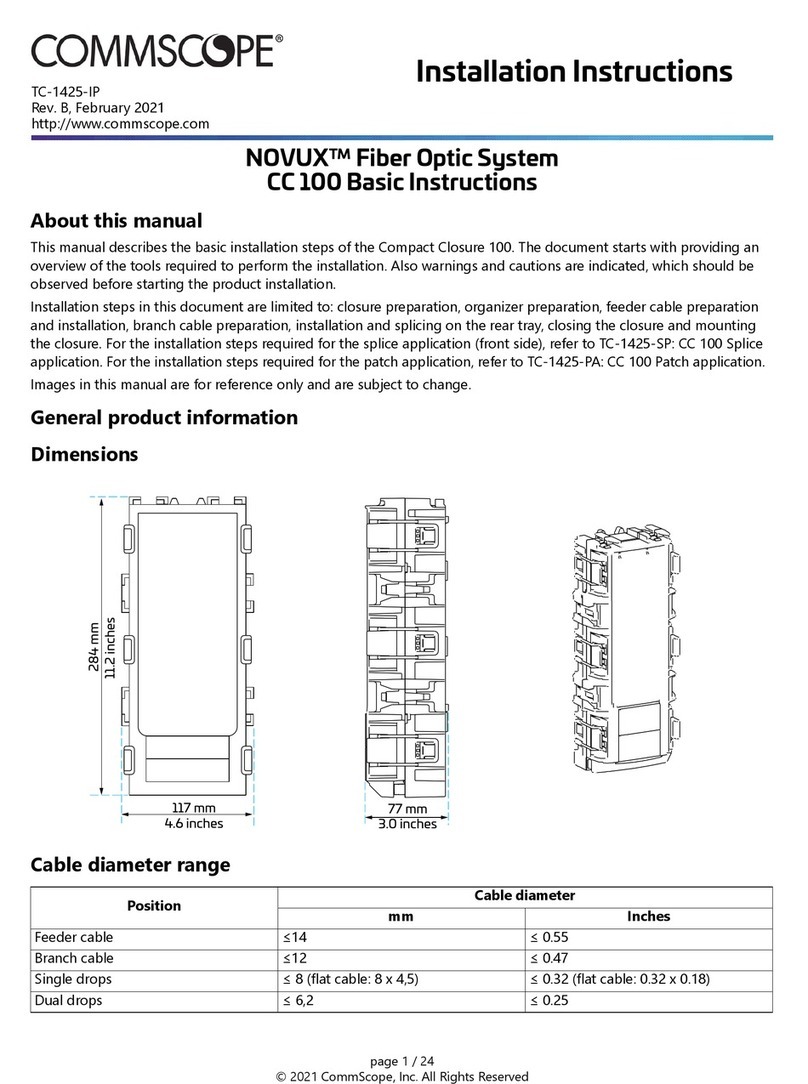
CommScope NOVUX Compact Closure 100 Series User manual

CommScope

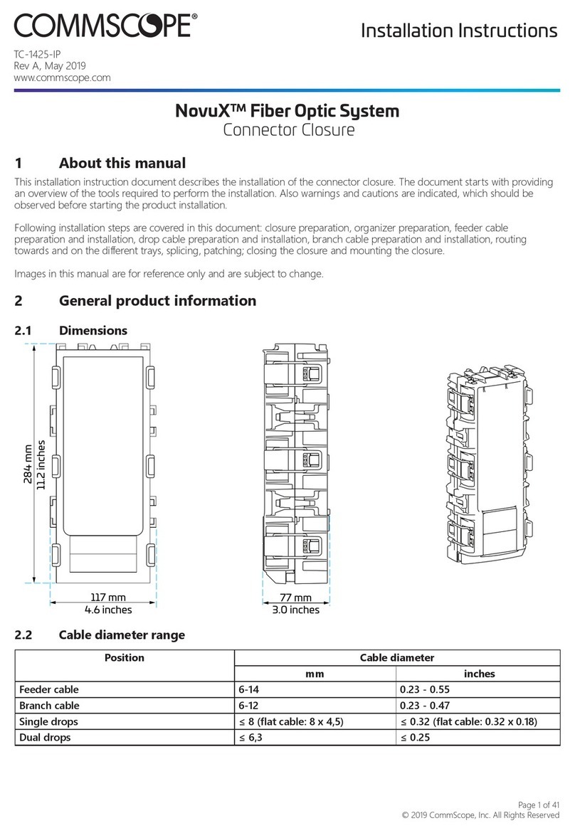
CommScope NOVUX Compact Closure 100 Series User manual

CommScope Mini-OTE 200 Series User manual

CommScope

CommScope Mini-OTE 200 Series User manual

CommScope CHD Series User manual

CommScope

CommScope CHD Series User manual

CommScope RFP User manual

CommScope

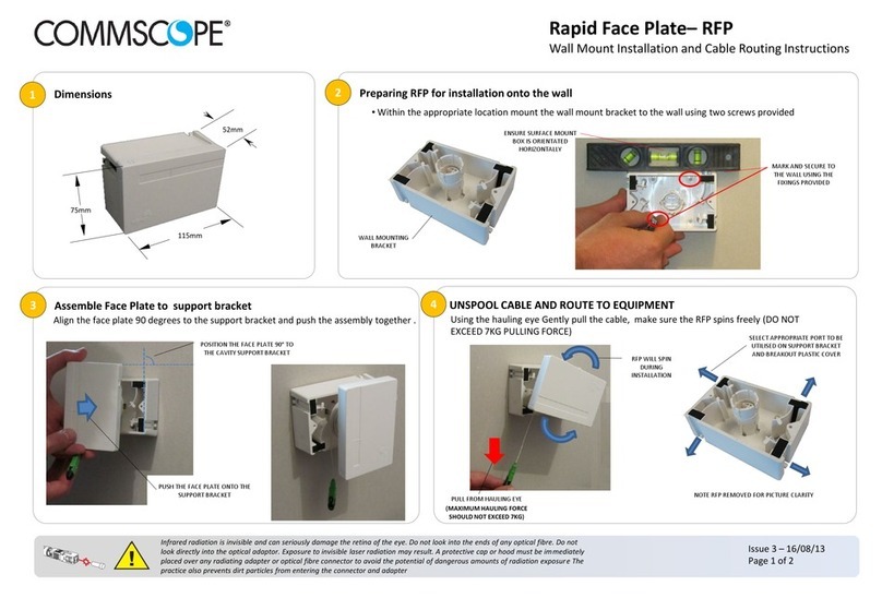
CommScope RFP User manual

CommScope FOSC-450A User manual

CommScope

CommScope FOSC-450A User manual

CommScope MDCC User manual

CommScope

CommScope MDCC User manual

CommScope OFDC-B8G User manual

CommScope

CommScope OFDC-B8G User manual
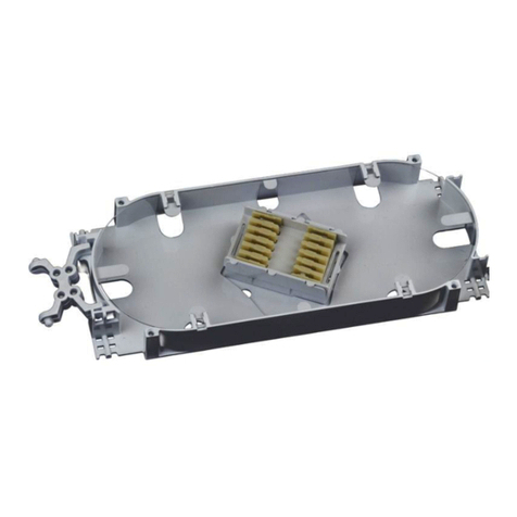
CommScope TENIO User manual

CommScope

CommScope TENIO User manual

CommScope FOSC-500-AA User manual

CommScope

CommScope FOSC-500-AA User manual

CommScope FOSC-450-BS User manual

CommScope

CommScope FOSC-450-BS User manual

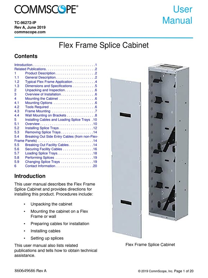
CommScope Flex Frame Splice Cabinet User manual

CommScope

CommScope Flex Frame Splice Cabinet User manual

CommScope FTUO User manual

CommScope

CommScope FTUO User manual

CommScope ODF-SPLCAB-24 User manual

CommScope

CommScope ODF-SPLCAB-24 User manual

CommScope AEKT User manual

CommScope

CommScope AEKT User manual

CommScope BUDI-M-FPS User manual

CommScope

CommScope BUDI-M-FPS User manual

CommScope FOSC-ACC-B-TRAY-12-RBN User manual
CommScope

CommScope FOSC-ACC-B-TRAY-12-RBN User manual

CommScope AMP NETCONNECT 2U Multi-Fiber Push-On User manual

CommScope

CommScope AMP NETCONNECT 2U Multi-Fiber Push-On User manual

CommScope FOWB User manual

CommScope

CommScope FOWB User manual

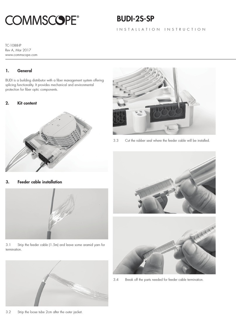
CommScope BUDI-2S-SP User manual

CommScope

CommScope BUDI-2S-SP User manual

CommScope NovuX Fiber Optic System User manual

CommScope

CommScope NovuX Fiber Optic System User manual

CommScope FDH 3000 User manual

CommScope

CommScope FDH 3000 User manual

CommScope NOVUX CC 100 User manual

CommScope

CommScope NOVUX CC 100 User manual

Popular Enclosure manuals by other brands

Antec Veris Fusion Remote Max Specification sheet

Antec

Antec Veris Fusion Remote Max Specification sheet

ENERMAX iVektor.Q ECA 3371 Series user manual

ENERMAX

ENERMAX iVektor.Q ECA 3371 Series user manual

Lindy 43095 user manual

Lindy

Lindy 43095 user manual

SICK C4000 Select operating instructions

SICK

SICK C4000 Select operating instructions

Geeek A60 PLUS installation guide

Geeek

Geeek A60 PLUS installation guide

OVE SYDNEY 48 installation manual

OVE

OVE SYDNEY 48 installation manual

SilentiumPC Armis AR5 Hardware installation

SilentiumPC

SilentiumPC Armis AR5 Hardware installation

Pulsar 17/TRP80/DSPR Assembly instructions

Pulsar

Pulsar 17/TRP80/DSPR Assembly instructions

MSI MPG SEKIRA 500X quick start guide

MSI

MSI MPG SEKIRA 500X quick start guide

Antec Dark fleet DF-10 user manual

Antec

Antec Dark fleet DF-10 user manual

Peavey DS 1502 Specifications

Peavey

Peavey DS 1502 Specifications

D-Link ShareCenter Pro DNS-1550-04 user manual

D-Link

D-Link ShareCenter Pro DNS-1550-04 user manual

Rosewill RX82-U(JBOD) user manual

Rosewill

Rosewill RX82-U(JBOD) user manual

QNAP SAS JBOD CLI 1.0 user guide

QNAP

QNAP SAS JBOD CLI 1.0 user guide

GAMDIAS Talos P1 Quick installation guide

GAMDIAS

GAMDIAS Talos P1 Quick installation guide

Auvs KR615 user manual

Auvs

Auvs KR615 user manual

Antec AR300 user manual

Antec

Antec AR300 user manual

FS FHD-FWME4 quick start guide

FS

FS FHD-FWME4 quick start guide

manuals.online logo
manuals.online logoBrands
  • About & Mission
  • Contact us
  • Privacy Policy
  • Terms and Conditions

Copyright 2025 Manuals.Online. All Rights Reserved.

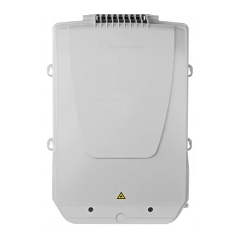
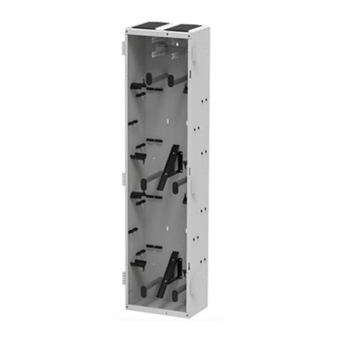
BUDI-M
INSTALLATION INSTRUCTION
Building distributor
• Box
• Base tray
• Base tower
• Termination units
• Inserts for SMOUV and ANT
Accessories
Introduction
Suitable for FTTH applications where easily pre-connectorized splitters
modules can be build in. The box is designed In such a way that it is
suitable for both spliced and connectorized solutions of the riser cable.
Kit content
• Tray kit
Seals
Wrap around cable seals
Sealblock 6 x 10 mm
Cable diameter (mm) Foam (± 5 mm)
3 95
4 90
5 80
6 75
7 70
8 60
9 50
10 40
Sealblock 6 x 15 mm
Cable diameter (mm) Foam (± 5 mm)
9 125
10 115
11 105
12 95
13 85
14 70
15 60
Sealblock 3 x 20 mm
Cable diameter (mm) Foam (± 5 mm)
14 155
15 140
16 125
17 110
18 95v
19 85
20 75
Sealblock 24 x 8 mm
Cable range A 1.8 – 5 mm
B 5 – 7 mm
Sealblock rubber 1 x 18
To use in ports S6-S7 only
Cable range 3 – 8 mm
Standard seals
PG 16
PG 21
PG 29
PG 29 (PTS 24)
TC-965-IP
Rev A, Feb 2017
www.commscope.com
2
1.2 Different wrap-around ports are available (including brackets).
Use two guiding pins to open the ports. Secure the bottom part to the
box with the screws.
1.4 Use a hacksaw to reach the onion rings, which can be opened
with a plier to open the in-line ports (S6/S7).
1.3 Install the cable bracket depending the cable seal..
Cut out plastic part, in case of installing a cable
1.1 Install the bracket if loop storage is needed.
1 Preparation of the box
S6 S7
3
2.2 Install the bracket and terminate the looped cable. Take out the
loose tube(s) from the basket for further use.
1.5 Install the wrap-around rubber seal into the port.
2.1 Cable installation into the wrap around ports. Bracket can be
different depending on the port. Secure with hook and loop fastener
tape and seal with foam (see length page 1).
2 Looped cable
3
2.3 Store the looped tubes in the basket.
Tie wraps / cable clamps
4
2.4 Route the loose tubes to the base tray. Mark left and right side
of the loose tube at their position on the base tray.
2.5 1: Storage area (looped storage shaved LT)
2: Splicing to splitter modules
3: Point-to-point applications
2.6 Store the unused looped fibers in the storage area.
2.7 Store the fibers which will be used later.
1
2
3
1
2
3
5
2.8 Store the fibers which will be spliced day 1 to the splitter
modules.
2.9 Store the fibers which will be spliced day 1 for the point-to-
point applications.
3.4 Install the terminated drop cable in the numbered ports on the
base tray.
3.3 Wrap one layer of foam (20 mm) on the securing position if
needed. Terminate the aramid strength member by securing the cable/
pigtail onto the bracket with tie-wrap. Depending the amount of aramid
strength member, it needs to be wrapped twice around the bracket.
3.1 Install the drop cable seal and push through the drop cable.
3.2 Remove the outer jacket over a distance of 1.2 m.
3 Drop cables (point-to-point applications)
2
3
6
3.6 Install the cover onto the tray.
4.1 Install the splitter holder
4 Splitters
3.5 Splice the fibers from the drop cable to the fibers from the
looped cable. In case of SMOUV, use the insert.
Slide
Click
7
4.3 Route the incoming pigtails of the splitter (marked with red flag)
to the base tray (area nr. 2). Remove the outer jacket from the mark over
a distance of 1.2m. Secure with foam and tie-wrap onto the base tray.
4.2 Install the splitter into the holder and route the pigtails via the
bend control.
OCM6 butt
Slide Click
OCM6 in-line
4.4 In case of splitter modules with integrated adaptors for the
incoming signal. Insert the connector of the pigtail in the adaptor of the
splitter and route the pigtail to the base tray. Remove the outer jacket
over a distance of 1.2 m and secure with foam and tie-wrap onto the
base tray.
8
4.5 To release the splitter module out of the splitter holder.
4.6 Splice the incoming of the splitter to the fibers coming from the
looped cable. In case of SMOUV, use the insert. Store the overlength in
the tray.
4.7 Install the cover onto the tray.
Click
Click
5 Patching trays
5.1 Install the patch tray onto the tower.
5.2 Insert the adaptor into the designated positions.
9
5.3 Install the drop seals and push the PICO cable through the
seals. Remove the outer jacket over a length of 1.5 m. Secure the cable
onto the bracket with foam and tie-wraps.
5.4 Install the pigtails and store the overlength in the splice area.
Mini-PICO (no connectors)
5.6 Install the foam at the position on the patch tray and secure
with 2 tie-wraps as shown on the picture.
5.5 Route the MINI PICO fibers behind the tower towards the patch
tray.
5.7 Install the splice holders onto the patch tray.
5.8 Splice the MINI PICO fibers to the pigtails and store the
overlength in the splice area. Check the orientation of both fibers to
avoid crossings.
10
5.9 Install the cover onto the tray.
5.10 In case of pre-connectorized MINI PICO cable, fibers are also
routed behind the tower and secured with foam and tie-wraps onto the
tray.
6.1 Route the pigtails through the bend control towards the patch
trays. Hook and loop fastener can be used to keep them bundled.
Mini-PICO (pre-conectorized)
6 Routing pigtails from the splitter
5.11 Store the overlength of the MINI PICO fibers in the splice area.
6.2 Route the pigtails through the cable clips for pigtail
management. Again hook and loop fastener can be used to keep them
in a bundle.
6.3 Install the cover onto the patch tray.