Spectro-UV Spectroline AccuPRO XP-2000A User manual

1
OPERATOR'S MANUAL
7/20 AM18029-2
PRINTED IN U.S.A.
AccuPRO™ Photometer/Radiometer
www.Spectro-UV.com
4 Dubon Ct., Farmingdale, NY 11735
866-230-7305
XP-2000A

2
CONTENTS
1. INTRODUCTION
1.1 GENERAL........................................................................................................................................….3
1.2 FEATURES.....................................................................................................................................…..3
1.3 PRECAUTIONS...................................................................................................................................3
2. GENERAL SPECIFICATIONS
2.1 AccuPRO PARTS AND COMPONENTS.........................................................................................….4
2.2 TECHNICAL SPECIFICATIONS ..........................................................................................................4
2.3 ELECTRICAL SPECIFICATIONS....................................................................................................….4
2.4 OPTICAL ACCURACY AND CALIBRATION........................................................................................4
2.5 ENVIRONMENTAL SPECIFICATIONS.................................................................................................4
3. BUTTONS AND CONTROLS 5
4. OPERATION––QUICK GUIDE.......................................................................................................5-6
5. USING THE AccuPRO
5.1 ON/OFF...........................................................................................................................................….6
5.2 OPERATION MODE......................................................................................................................…. 6
5.3 SENSOR READOUTS AND PEAK VALUE........................................................................................ 6
5.4 SENSOR WAVELENGTHS & RANGES........................................................................................... 6
6. CUSTOMIZING SETTINGS
6.1. CHANGING UNITS .........................................................................................................................….7
6.2 ADJUSTING BRIGHTNESS.............................................................................................................…7
6.3 LANGUAGE OPTIONS...............................................................................................................….8
7. INFORMATON 8
8. CALIBRATION 8-9
9. THEORY OF OPERATION…............................................………………………..…................9
10. WARRANTY, MAINTENANCE AND BATTERY
10.1 WARRANTY......................................................................................................................................10
10.2.PREVENTIVE MAINTENANCE.........................................................................................................10
10.3 BATTERY CHARGING .............................................................................................................10
© 2020 by Spectro-UV. All rights reserved. No part of this publication may be reproduced or transmitted in any form or by any
means, electronic or mechanical, including photocopying, recording, or any information storage and retrieval system, without
permission in writing from the copyright owner. Requests should be made through Spectro-UV.

3
1. INTRODUCTION
1.1 GENERAL
The AccuPRO™ XP-2000A Meter features an advanced
digital microprocessor-controlled readout unit calibrated
to accurately detect and display light intensity readings.
The XP-2000A features UV and white light modes, and
are used for fluorescent inspection (non-destructive
testing).
1.2 FEATURES
• The meter is compact, lightweight, and
battery-operated for convenient use in the factory,
field, or any other location where measurements
need to be taken.
• The XP-2000A readout unit has a maximum 4-digit
autoranging, color LCD screen.
• The sensor is loaded with low electrical impedance,
making their linearity vastly superior to that of any
other comparably priced radiometers.
• The sensor is provided with a special diffuser
window that helps prevent filter degradation and
ensures accurate lambertian or cosine response.
INTERFACE
• Simple, three-button interface
• Accurate to within a hundredth of a unit
measurement (e.g., 28.96 mW/cm2)
• Intuitive user interface design
• Navigable screen prompts
• One touch PEAK reset
• Toggle between UV/Visible and Blue Light modes
HARDWARE
• Sensor with 3-foot (0.9 m) electrical cord
• Superior band-pass interference filter provides
excellent cosine response
• Press and hold the MENU button to turn the meter
ON or OFF
• Powered by four AAA rechargeable nickel-metal
hydride batteries with AC battery charger included
1.3 PRECAUTIONS
• The AccuPRO is carefully designed to prevent
accidental shock to the operator. However, no
engineering design can render safe an instrument
that is used carelessly. Therefore, the directions
presented in this manual must be read carefully
before any measurements are made. Failure to
follow directions could result in injury.
• The UV sensor is designed for use in regions of the
spectrum, notably the ultraviolet range, which may
be hazardous to the eyes and/or skin. Ultraviolet
protective eyewear and facewear are available from
Spectro-UV (for instances when UV exposure is
unavoidable).
• Do not leave the exposed sensor head under the
light source any longer than necessary to take
measurements. Prolonged exposure can result in
premature aging of the sensor, necessitating more
frequent recalibration to maintain accurate readings.
• See Section 10, Warranty, Maintenance and Battery
information.
• DO NOT CHARGE ALKALINE BATTERIES (doing
so may result in an explosion, potentially causing
damage to the unit and/or operators). Only use the
supplied batteries.
2. AccuPRO COMPONENTS
• Unpack and inspect the component(s) for
possible damage in shipment. Save the shipping
carton and packing materials for future storing or
shipping of the AccuPRO components.
• Assure the sensor cable is undamaged and
securely attached to the readout unit.
• Conduct a performance test as soon as possible.
If any damage is noted, immediately notify the
carrier and supplier (do not use the instrument).
• While charging, it is recommended to have the
device turned OFF.

4
2.2 TECHNICAL SPECIFICATIONS
2.3 ELECTRICAL SPECIFICATIONS
A full charge of the four nickel-metal hydride batteries
(using the included AC battery charger) will take 8
hours and provide approximately 6 hours of active
scanning.
2.4 OPTICAL ACCURACY AND CALIBRATION
The AccuPRO XP-2000A readout unit measures both
ultraviolet and visible light. The LCD readout features
±0.2% linearity with the sensor sending the linearity
correction data to the readout unit during initial power-
up. The sensor is designed with superior band-pass
filters, and the optical stacks are assembled in Class
100 clean workstations to ensure consistent results.
For precise spectral coverage, these high-quality
interference filters will effectively resist degradation.
See Section 8 for additional calibration-related
information.
If recalibration is required, Contact Spectro-UV at
1-516-333-4859 for assistance.
2.5 ENVIRONMENTAL SPECIFICATIONS
The AccuPRO meter series components are designed
to be safe under the following conditions:
• Indoor use;
• Altitude up to 2,000 m (6,562 ft.);
• Temperature 5°C to 40°C (41°F to 104°F);
• Maximum relative humidity 80% for temperatures
up to 31°C (88°F) decreasing linearly to 50% rela-
tive humidity at 40°C (104°F);
• Mains supply voltage fluctuations not to exceed
±10% of the nominal voltage;
• Installation Category II;
• Pollution Degree 2.
DIMENSIONS
Part Length Width Depth Weight
Readout
Unit
6 in
(15.2 cm)
3.0 in
(7.6 cm)
1.0 in
(2.5cm)
8 oz
(227 gm)
Sensor 3.0 in
(7.6 cm)
2.0 in
(5.1 cm)
0.5 in
(1.25 cm)
5.6 oz
(158.7gm)
2.1 AccuPRO™ PARTS
AccuPRO™ XP-2000A Meter with
Multi-Wavelength Sensor
XCC-200
Rechargeable AAA Nickel-Metal
Hydride batteries (4)
AC Battery Charger
(North American plug shown, see
replacement parts for complete list)
COMPONENTS AND REPLACEMENT PARTS
Part No. Description
XP-2000A AccuPRO Dual Sensor (UV-A/VIS), Multilingual
Display Meter
XCC-200 Soft Carrying Case
XP-2000A/F XP-2000A with European Plug (230V/50Hz)
XP-2000A/FB XP-2000A with UK Plug (230V/50Hz)
XP-2000A/FA XP-2000A with Australia/China Plug
(220-240V/50Hz)
129450
AC Charger with North American Plug (120V/60Hz)
129451 AC Charger with European Plug (230V/50Hz)
129453
AC Charger with UK Plug
(230V/50Hz)
129452 AC Charger with Australia/China Plug (220-240V/50Hz)
Soft Carrying Case
5
3. BUTTONS AND CONTROLS
• The keypad on the readout meter is equipped with three pressure-sensitive
buttons that provide easy access to all functions and features.
• Press and hold down the MENU (ON/OFF) button to turn the meter ON.
• The UP and DOWN arrows to the left and right of the MENU button provide
access to all displays and features. Selected menu items appear highlighted in
blue. Selected Menu items can be confirmed by pressing the MENU button once.
• Pressing the DOWN arrow (while in OPERATION MODE) will reset the PEAK
value (highest recorded luminescence since last reset) for visible and UV light
sources.
• Press and hold the MENU button in OPERATION mode to turn the unit OFF.
• Highlighting and selecting the BACK button will return the user to the previous
screen without making any changes.
4. OPERATION––QUICK GUIDE
1. To turn the meter ON, press and hold the MENU button for two seconds. It is recommended
to fully charge the unit before use (see section 10.3).
2. The Spectroline®loading screen will appear as the unit powers ON. Information pertaining to
your device will briefly appear as well. Select INFORMATION from the MAIN MENU screen to
thoroughly examine information pertaining to your device (see Section 6).
3. After loading, the unit will boot directly to Operation mode, displaying visible and UV readings
by default. To change meter display settings, press MENU. Then select the SETTINGS option.
When highlighted, press MENU to enter SETTINGS menu (see SETTINGS section for
details).
4. To take a measurement, enter Operation Mode. Shine a light source directly over the center
of the sensor. The measurement will display on the interface screen.
5. The meter instantly displays light level data for each wavelength (intensity/unit area).
6. To turn off the meter, press and hold the MENU button for 2 seconds while in Operation mode.
The display will then power off. Wait at least 30 seconds after the meter powers down before
performing a RESTART (by pressing and holding MENU for 2 seconds). The AccuPRO will
only power off from Operation mode, and not from the menus.
7. To both conserve battery life and preserve the sensitivity of the sensor head, utilize the "Set
Auto-Off" function under the "SETTINGS" menu. (See section 6).
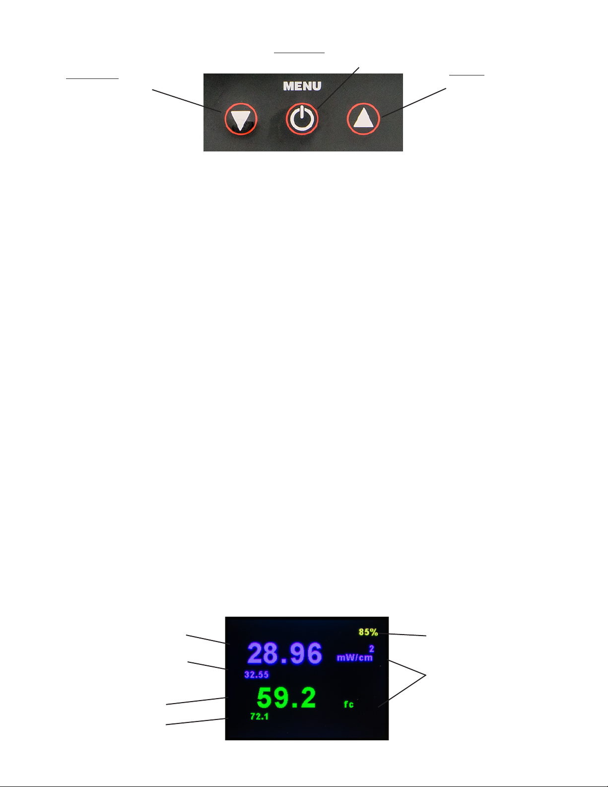
DOWN Key:
Reset PEAK Value
UP Key:
Toggle VIS/UV
MENU Key:
Adjust settings, confirm choices
Operation Mode for Visible and UV Light Sources
UV-A Reading
Visible Reading
Units
UV PEAK Value
Battery Indicator
VIS PEAK Value

6
5. USING AccuPRO
5.1 ON/OFF
Press and hold the MENU button to turn the meter on.
Boot screen below followed by Information screen
(section 7) will display. Fully charge before use.
5.2 OPERATION MODE
When turned on, the AccuPRO automatically enters
Operation Mode and begins displaying light readings
for white light (555nm) and UV (365nm) wavelengths.
5.3 SENSOR READOUTS AND PEAK VALUE
Moving the sensor head will cause the readout values
to increase or decrease depending on the levels of
illumination, with the highest recorded value stored
automatically as the PEAK value in the lower left of the
readout screen. Images on pages 5 and 6 detail each
readout screen.
Shine the light source being measured directly over the
center of the sensor for the most accurate readings.
The PEAK value stores the maximum luminosity
recorded since the last reset. Simply press the DOWN
arrow in operational mode to reset the PEAK value to
zero across visible and UV light readouts.
5.4 SENSOR WAVELENGTHS & RANGES
The single sensor attached to the AccuPRO will
display UV-A (365nm) readings as well as visible light
(555nm). In addition, the AccuPRO Plus will also
display blue light at the wavelength of 450nm.
Meter will display "XXXX" should readings in any
measured portion of the spectrum exceed the figures
below:
6. CUSTOMIZING SETTINGS
Press MENU, then press the DOWN arrow. Select the
SETTINGS option. Press MENU again to enter the
SETTINGS menu as shown below:
Press and hold the MENU button to turn the meter ON.
The Boot Screen (below) will load, followed briefly by
the Information Screen. (See Section 7 for details about
the Information Screen).
Model No. Wavelengths Recorded Range
XP-2000A UV-A/VIS
UV-A (365nm) Irradiance
Visible (555nm) Illuminance
0_100 mW/cm2
0_5,300 Lux
0_500 fc

7
The SETTINGS menu contains the options displayed
below:
Press UP or DOWN to highlight the feature to be
modified and MENU to access the next screen. Highlight
BACK and press MENU to return to OPERATION mode.
6.1 CHANGING UNITS OF MEASUREMENT
The AccuPRO provides users the capability of setting
the default visible light unit of measure to either
foot-candles (fc) or Lux.
UV light source intensity units will autorange from µW/
cm2to mW/cm2.
To adjust units, highlight and select SET UNITS from
the SETTINGS menu. Press MENU to move to the next
screen, as shown below. Vis (Visible) and UV will be
listed, along with the BACK button to return to the
previous screen.
Select the desired portion of the spectrum using MENU,
then use the arrow keys to select the desired units. The
following example displays the options for visible light:
The example below shows the available units for
ultraviolet light:
Upon pressing MENU, a brief confirmation screen will
display (e.g., "Units set to Lux") before returning to the
main menu. Simply press MENU again to return to
Operation Mode which will display the new units.
6.2 ADJUSTING BRIGHTNESS
To change the brightness of the screen, enter the
SETTINGS menu. Select BRIGHTNESS. Press MENU
to access brightness settings and choose either
BRIGHTER or DARKER (see example below). When
selecting the level of brightness, consider the ambient
light conditions, user preferences, and battery
conservation.
Press the MENU button until desired brightness
level is attained. Press BACK to confirm and exit.

8
6.3 LANGUAGE OPTIONS
All interactive features and displays of the AccuPRO
and AccuPRO Plus are available in English, Spanish,
German, French, and Chinese. Enter the SETTINGS
menu and select the LANGUAGE option to enter the
selection menu displayed below. Upon selection of the
desired language, the language menu will refresh and
appear in the newly selected language format.
NOTE: Should the language accidentally be changed
to one which you cannot understand, the first (highest)
option on the menu will revert to English as seen
below.
Below is the same screen viewed in Chinese. The
numbers remain the same. In this event, press
UP until reaching option 1 then MENU to return to
English. The same is applicable to the other
languages, with the first option reverting to English.
7. INFORMATION
The INFORMATION screen, accessed via the third
selection on the main menu, displays briefly when the
device is powered on, and can be viewed for as long
as desired through the menu option.
Important data including the serial number of your unit,
date of last calibration, and software version is avaiable
on the INFORMATION screen. This information will
differ between the example below and your own unit.
To return to OPERATION Mode, select the BACK
option.
8. CALIBRATION
The fourth and final option on the Main Menu is
Calibration. Calibration requires a precise configuration,
and cannot be performed with the device alone. Contact
customer service at 1-516-333-4859 if you believe your
AccuPRO may require calibration.
There is no need to enter this menu under normal
circumstances. However, should you arrive on the
calibration screen shown below, simply press MENU
repeatedly to exit.
The languages and their corresponding numbers
match across all language settings. If you accidentally
happen to select a language difficult to understand
(for instance, Chinese), select Option Number 1 to
revert back to the default English language setting.
The same process is applicable to the other languages
in the selection.
The INFORMATION Screen can be accessed in the Main
Menu. By default, the INFORMATION Screen briefly
displays during startup. To closely examine the data on
the INFORMATION Screen, select INFORMATION from
the Main Menu.
The serial number of your device, the date of your
device’s most recent calibration, and the software
version installed on your device is available on the
INFORMATION screen.

9
Zeroes will appear in the Response field each time
the MENU button is pressed. The text "Verify Bad"
will display (as shown below) and the device will then
automatically exit the calibration screen, returning to
the Main Menu by default.
THE INPUT OPTICS
The lambertian (cosine) response of the sensor head
is desirable for many measurement applications,
especially those where the angle from the source to
the detector is variable or those situations where the
angle from the source is ''extended,'' such as in the
measurement of a fluorescent lamp at distances
comparable to or shorter than its length. In the latter
case, the extended source provides radiation from
many angles, all of which must be properly ''weighted''
as to their effectiveness on the plane represented by
the sensor surface.
In actual practice, it is difficult to make a sensor
conform to the ideal response over the entire solid
angle of 2TT steradians. The sensor units of the
AccuPRO meter minimize this problem by being
outfitted with optimal transmission diffusing materials
for various spectral regions. These diffusion materials
are mounted close to the surface of the sensors so
that the oblique rays are not obstructed. The spectral
range is selected by adding an appropriate UV
interference filter within the optical stack before the
sensor cell assembly.
THE SENSOR CELL
Photovoltaic Operation
When a p-n junction is operated with no externally
applied voltage, it is considered to be operating in the
photovoltaic mode. Under this zero applied voltage
condition and low levels of incident light, the p-n
junction will generate a current proportional to the light
power incident on the active surface.
This photon-induced current, or photocurrent, will
divide between the diode parallel dynamic resistance
and the parallel load resistance. The dynamic
resistance is normally a high value and is an inverse
exponential function of forward voltage. The direction
of current flow will produce a voltage across the diode
that opposes the band-gap potential of the photodiode
junction, thus forward biasing it. As a result, the value
of the diode dynamic resistance (Rd) drops
exponentially as the irradiance increases and the
photo generated voltage is a quasilogarithmic function
of diode irradiance when the external load resistance
is considered. Another major disadvantage is that Rd
typically has a wide spread of values over different
production batches.
One way of achieving sufficiently low load resistance
and eliminating the effect of the diode parallel
resistance is to feed the photocurrent into the virtual
ground of an operational amplifier. The output voltage
is the result of the photocurrent being driven by the
amplifier through the feedback resistor and the input
impedance Rin = Rf/A where A is the open loop gain
and Rf the feedback resistor. This circuit has a linear
response and is low noise due to the almost complete
elimination of leakage current with the zero bias. This
results in a proportional voltage being presented to
the signal conditioning section of the electronics.
LIGHT
OPTICAL STAGE,
A/D CONVERSION,
PROGRAMMABLE
CIRCUITRY
MICROPROCESOR
CONTROL
GRAPHICAL
DISPLAY
SIGNAL PROCESSING
SENSOR CIRCUIT
9. THEORY OF OPERATION

10
10. WARRANTY, MAINTENANCE
AND BATTERY REPLACEMENT
10.1 WARRANTY
The warranty policy for the AccuPRO is provided
on the Certificate of Limited Warranty enclosed
separately with each unit.
NOTE: For assistance of any kind, including help
with a meter under warranty, contact the
Customer Service Department at Spectro-UV.
In the United States and Canada, call toll-free
1-866-230-7305. Include the model number,
serial number, and date of purchase. If return of
the unit is deemed necessary, shipping
instructions will be provided. If an estimate of
charges for nonwarranty work or other service
work is required, a quote will be furnished upon
evaluation of the unit. Out-of-warranty service
work will not be performed without customer
approval.
10.2 PREVENTIVE MAINTENANCE
• Immediately clean all spilled materials from the
unit and wipe dry. If necessary, moisten a cloth
with soap and water to clean plastic surfaces
and the sensor head. The sensor surface
should be rinsed with ethanol to remove any
residual soap and/or organic contaminants.
• Whenever possible, avoid exposure or use in
areas that are subject to temperature and
humidity extremes, vibration or mechanical
shock, dust or corrosive fumes, or strong
electrical or electromagnetic interference.
• It is recommended that the unit be returned to
the factory or a recognized SpectrolineAccuPRO
calibration service center for a complete overall
check and recalibration at least every 6 or 12
months, depending on your facility's Standard
Operating Procedures. Before returning the
units to our factory, contact the Customer
Service Department for shipping instructions.
• When the AccuPRO is not in use, store it in a
location free from temperature extremes, dust
or corrosive fumes, and vibration or mechanical
shock.
• If storing for an extended period, place the
AccuPRO in its carrying case.
10.3 BATTERY SAFETY AND CHARGING
1. The AccuPRO radiometer must be charged
overnight or for at least 8 hours when the
battery is replaced or after a battery reset
(removal and re-installation of the same battery).
2. CAUTION: Do not use alkaline batteries in the
AccuPRO as they may explode causing damage
to the circuitry and possibly the operators. Only
use the 700mAh,1.2V rechargeable batteries
provided with the AccuPRO and available from
Spectroline®(P/N: 129227).
3. The AccuPRO should be charged with the
power OFF. Charging the unit for long periods
while operating is not advised because it will
cause the charging/display circuit to malfunction.
Should this take place, the unit will need to
charge for 8+ hours while turned off for the
circuit to reset.
4. The battery indicator will turn red at 30%. It is
recommended that the AccuPRO be powered
down and charged when it reaches this level. At
10% battery life, the unit will automatically
power down.
5. Disconnect the charger from the meter when
not in use.
6. While charging, it is recommended to have the
device turned OFF.
7. Off-State Discharge Rate: The AccuPRO™
battery will naturally discharge approximately
3-4% per day – even when the unit is turned off.
Be sure to keep an accurate and up-to-date
charging schedule.
CHARGING
• Plug battery charger into AC power outlet.
• Firmly connect charger to port located on the
right side of the unit, just below the screen.
• Battery percentage, located in the top right
corner of the screen, will begin to increase as
the unit charges. It might be necessary to
change screens for the battery readout to
update.
• A full charge will take 8 hours and is good for
approximately 6 hours of operation.
• While charging, it is recommended to have the
device turned OFF.
For product information and technical assistance, call us at 1-866-230-7305.
Consult Safety Data Sheet (SDS) on our website at www.Spectro-UV.com.

11

12
www.Spectro-UV.com
4 Dubon Ct., Farmingdale, NY 11735
866-230-7305
Other manuals for Spectroline AccuPRO XP-2000A
1
Table of contents
Other Spectro-UV Measuring Instrument manuals


