Spectro-UV Spectroline AccuPRO XP-4000 User manual
1
OPERATOR'S MANUAL
7/20 AM15002ML-2
PRINTED IN U.S.A.
AccuPRO™ Photometer/Radiometer
www.Spectro-UV.com
4 Dubon Ct., Farmingdale, NY 11735
866-230-7305
XP-4000 & XP-2000
ENG - 1 FR - 9 ES - 17 DE - 25

2
CONTENTS
1. INTRODUCTION
1.1 GENERAL........................................................................................................................................….3
1.2 FEATURES.....................................................................................................................................…..3
1.3 PRECAUTIONS...................................................................................................................................3
2. GENERAL SPECIFICATIONS
2.1 AccuPRO PARTS AND COMPONENTS.........................................................................................….4
2.2 TECHNICAL SPECIFICATIONS ..........................................................................................................4
2.3 ELECTRICAL SPECIFICATIONS....................................................................................................….4
2.4 OPTICAL ACCURACY AND CALIBRATION........................................................................................4
2.5 ENVIRONMENTAL SPECIFICATIONS.................................................................................................4
3. BUTTONS AND CONTROLS 5
4. OPERATION––QUICK GUIDE.......................................................................................................5-6
5. USING THE AccuPRO
5.1 ON/OFF...........................................................................................................................................….6
5.2 OPERATION MODE......................................................................................................................…. 6
5.3 SENSOR READOUTS AND PEAK VALUE........................................................................................ 6
5.4 SENSOR WAVELENGTHS & RANGES........................................................................................... 6
6. CUSTOMIZING SETTINGS
6.1. CHANGING UNITS ........................................................................................................................….7
6.2 ADJUSTING BRIGHTNESS.............................................................................................................…7
6.3 LANGUAGE OPTIONS...............................................................................................................….8
7. INFORMATON 8
8. CALIBRATION 8-9
9. THEORY OF OPERATION…............................................………………………..…................10
10. WARRANTY, MAINTENANCE AND BATTERY
10.1 WARRANTY......................................................................................................................................11
10.2.PREVENTIVE MAINTENANCE.........................................................................................................11
10.3 BATTERY CHARGING .............................................................................................................11
© 2020 by Spectro-UV. All rights reserved. No part of this publication may be reproduced or transmitted in any form or by any
means, electronic or mechanical, including photocopying, recording, or any information storage and retrieval system, without
permission in writing from the copyright owner. Requests should be made through Spectro-UV.

3
1. INTRODUCTION
1.1 GENERAL
The AccuPRO™ (XP-2000) and AccuPRO™ Plus (XP-
4000) Meter Series features an advanced digital
microprocessor-controlled readout unit calibrated to
accurately detect and display light intensity readings.
The XP-2000 and XP-4000 (with attached sensor)
feature UV, blue (XP-4000 only), and white light modes,
and are used for fluorescent inspection (non-destructive
testing).
The XP-4000 readout unit is calibrated for HID UV,
visible, and blue light sources. It provides UV-A and blue
light readings from 0-100 mW/cm2, visible light readings
from 0-5,300 lux (0-500 fc), and is useful for NDT
applications with simple, one-touch PEAK functionality to
easily identify the strongest point of a light source.
1.2 FEATURES
• The meters are compact, lightweight and battery-
operated for convenient use in the factory, field, or
any other location where measurements need to be
taken.
• The XP-2000 and XP-4000 readout units have a
maximum 4-digit autoranging, color LCD screen.
• The sensor is loaded with low electrical impedance,
making their linearity vastly superior to that of any
other comparably priced radiometers.
• The sensors are provided with a special diffuser-
sensor window that helps prevent filter degradation
and ensures accurate lambertian or cosine response.
INTERFACE
• Simple, three-button interface
• Accurate to within a hundredth of a unit
measurement (e.g., 28.96 mW/cm2)
• Intuitive user interface design
• Navigable screen prompts
• One touch PEAK reset
• Toggle between UV/Visible and Blue Light modes
HARDWARE
• Sensor with 3-foot (0.9 m) electrical cord
• Superior band-pass interference filter provides
excellent cosine response
• Press and hold the MENU button to turn the meter
ON or OFF
• Powered by four AAA rechargeable nickel-metal
hydride batteries with AC battery charger included
1.3 PRECAUTIONS
• The AccuPRO is carefully designed to prevent
accidental shock to the operator. However, no
engineering design can render safe an instrument
that is used carelessly. Therefore, the directions
presented in this manual must be read carefully
before any measurements are made. Failure to
follow directions could result in injury.
• The UV sensor is designed for use in regions of the
spectrum, notably the ultraviolet range, which may
be hazardous to the eyes and/or skin. Ultraviolet
protective eyewear and facewear are available from
Spectro-UV (for instances when UV exposure is
unavoidable).
• Do not leave the exposed sensor head under the
light source any longer than necessary to take
measurements. Prolonged exposure can result in
premature aging of the sensor, necessitating more
frequent recalibration to maintain accurate readings.
• See Section 10, Warranty, Maintenance and Battery
information.
• DO NOT CHARGE ALKALINE BATTERIES (doing
so may result in an explosion, potentially causing
damage to the unit and/or operators). Only use the
supplied batteries.
2. AccuPRO COMPONENTS
• Unpack and inspect the component(s) for possible
damage in shipment. Save the shipping carton
and packing materials for future storing or shipping
of the AccuPRO components.
• Assure the sensor cable is undamaged and
securely attached to the readout unit.
• Conduct a performance test as soon as possible.
If any damage is noted, immediately notify the
carrier and supplier (do not use the instrument).
• While charging, it is recommended to have the
device turned OFF.
4
2.2 TECHNICAL SPECIFICATIONS
2.3 ELECTRICAL SPECIFICATIONS
A full charge of the four nickel-metal hydride batteries
(using the included AC battery charger) will take 8
hours and provide approximately 6 hours of active
scanning.
2.4 OPTICAL ACCURACY AND CALIBRATION
The AccuPRO XP-2000 and XP-4000 readout units
measure both ultraviolet and visible light. The AccuPRO
Plus (XP-4000) also measures blue light. The LCD
readout features ±0.2% linearity with the sensor
sending the linearity correction data to the readout unit
during initial power-up. The sensor is designed with
superior band-pass filters and the optical stacks are
assembled in Class 100 clean workstations to ensure
consistent results. For precise spectral coverage, these
high-quality interference filters will effectively resist
degradation. See Section 8 for additional calibration-
related information.
If recalibration is required, Contact Spectro-UV at
1-866-230-7305 for assistance.
2.5 ENVIRONMENTAL SPECIFICATIONS
The AccuPRO meter series components are designed
to be safe under the following conditions:
• Indoor use;
• Altitude up to 2,000 m (6,562 ft.);
• Temperature 5°C to 40°C (41°F to 104°F);
• Maximum relative humidity 80% for temperatures
up to 31°C (88°F) decreasing linearly to 50% rela-
tive humidity at 40°C (104°F);
• Mains supply voltage fluctuations not to exceed
±10% of the nominal voltage;
• Installation Category II;
• Pollution Degree 2.
DIMENSIONS
Part Length Width Depth Weight
Readout
Unit
6 in
(15.2 cm)
3.0 in
(7.6 cm)
1.0 in
(2.5cm)
8 oz
(227 gm)
Sensor 3.0 in
(7.6 cm)
2.0 in
(5.1 cm)
0.5 in
(1.25 cm)
5.6 oz
(158.7gm)
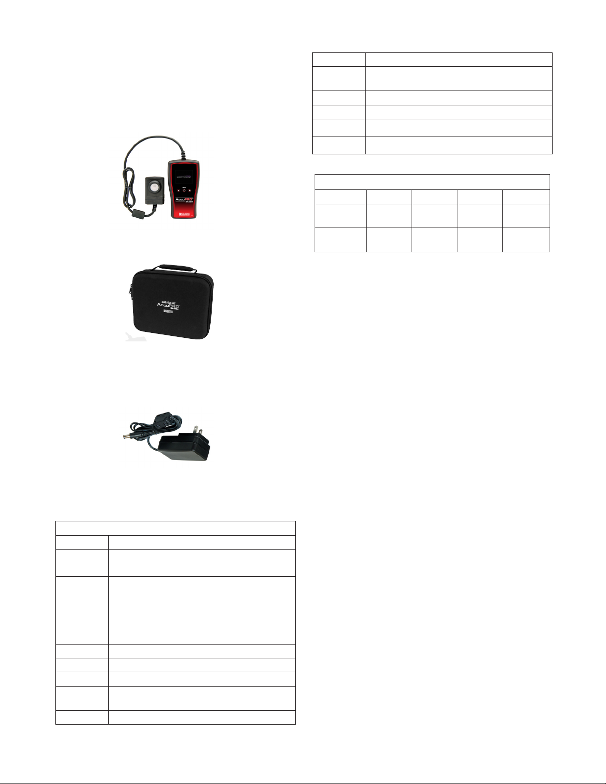
2.1 AccuPRO™ PARTS
AccuPRO™ Meter with
Multi-Wavelength Sensor
XP-2000 (AccuPRO) and XP-4000
(AccuPRO Plus)
XCC-200
Rechargeable AAA Nickel-Metal
Hydride batteries (4)
AC Battery Charger
(North American plug shown, see
replacement parts for complete list)
COMPONENTS AND REPLACEMENT PARTS
Part No. Description
XP-2000 AccuPRO Dual Sensor (UV-A/VIS), Multilingual
Display Meter
XP-4000 AccuPRO Plus 3-in-1 Sensor (UV-A/VIS/Blue),
Multilingual Display Meter, Complete with (4)
Rechargeable “AAA” Nickel-Metal Hydride
Batteries, AC Charger and Carrying Case
(100-120V/50-50Hz)
XCC-200 Soft Carrying Case
XP-2000/F XP-2000 (with 230V/50Hz European Plug)
XP-2000/FB XP-2000 with UK Plug (230V/50Hz)
XP-2000/FA XP-2000 with Australia/China Plug
(220-240V/50Hz)
XP-4000/F XP-4000 with European Plug (230V/50Hz)
XP-400/FB XP-4000 with UK Plug (230V/50Hz)
XP-4000/FA XP-4000 with Australia/China Plug
(220-240V/50Hz)
129450
AC Charger with North American Plug (120V/60Hz)
129451 AC Charger with European Plug (230V/50Hz)
129453
AC Charger with UK Plug
(230V/50Hz)
129452 AC Charger with Australia/China Plug (220-240V/50Hz)
Soft Carrying Case
5
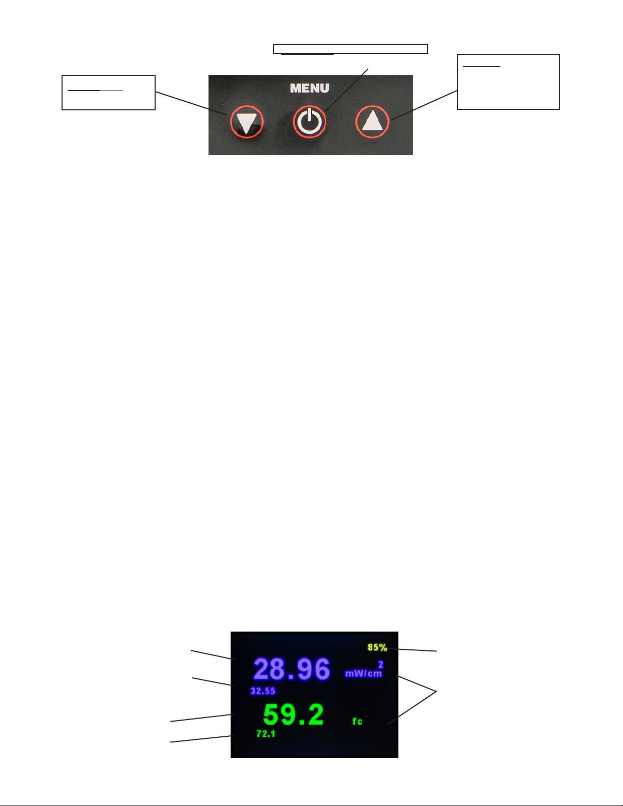
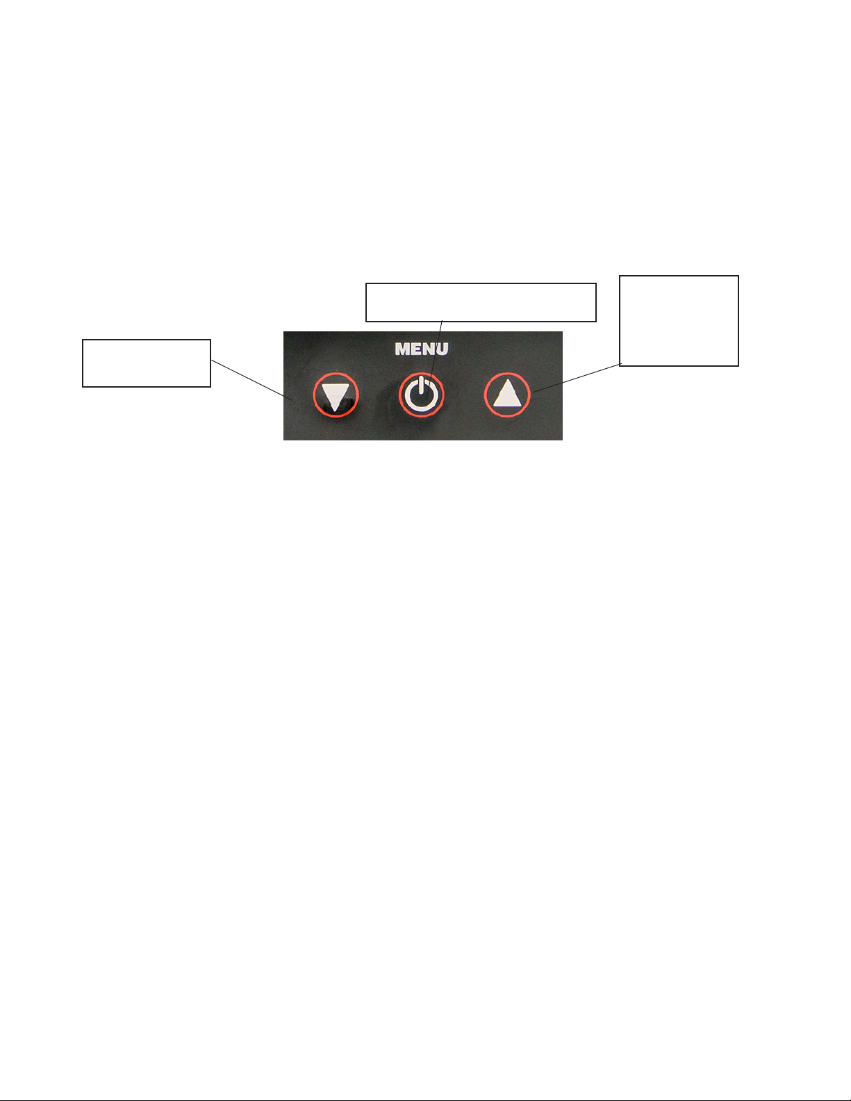
3. BUTTONS AND CONTROLS
• The keypad on the readout meter is equipped with three pressure-sensitive
buttons that provide easy access to all functions and features.
• Press and hold down the MENU (ON/OFF) button to turn the meter ON.
• The UP and DOWN arrows to the left and right of the MENU button provide
access to all displays and features. Selected menu items appear highlighted in
blue. Selected Menu items can be confirmed by pressing the MENU button once.
• Pressing the DOWN arrow (while in OPERATION MODE) will reset the PEAK
value (highest recorded luminescence since last reset) for visible, UV, and if
applicable, blue light sources. If using the AccuPRO Plus (XP-4000), the UP
arrow toggles between Visible/UV and blue light readouts.
• Press and hold the MENU button in OPERATION mode to turn the unit OFF.
• Highlighting and selecting the BACK button will return the user to the previous
screen without making any changes.
4. OPERATION––QUICK GUIDE
1. To turn the meter on, press and hold the MENU button for two seconds. It is recommended
to fully charge the unit before use (see section 10.3).
2. The Spectroline®loading screen will appear as the unit powers ON. Information pertaining to
your device will briefly appear as well. Select INFORMATION from the MAIN MENU screen
to thoroughly examine information pertaining to your device (see Section 6).
3. After loading, the unit will boot directly to Operation mode, displaying visible and UV readings
by default. To view levels of blue light with the AccuPro Plus (XP-4000), press the UP button.
4. To change meter display settings, press MENU. Then select the SETTINGS option. When
highlighted, press MENU to enter SETTINGS menu (see SETTINGS section for details).
5. To take a measurement, enter Operation Mode. Shine a light source directly over the center
of the sensor. The measurement will display on the interface screen.
6. The meter instantly displays light level data for each wavelength (intensity/unit area).
7. To turn off the meter, press and hold the MENU button for 2 seconds while in Operation mode.
The display will then power off. Wait at least 30 seconds after the meter powers down before
performing a RESTART (by pressing and holding MENU for 2 seconds). The AccuPRO will
only power off from Operation mode, and not from the menus.
8. To both conserve battery life and preserve the sensitivity of the sensor head, utilize the "Set
Auto-Off" function under the "SETTINGS" menu. (See section 6).
DOWN Key:
Reset PEAK Value
UP Key:
Toggle VIS/UV or
BLUE modes
(XP-4000 only)
MENU Key:
Adjust settings, conrm choices
Operation Mode for Visible and UV Light Sources
UV-A Reading
Visible Reading
Units
UV PEAK Value
Battery Indicator
VIS PEAK Value
6
5. USING AccuPRO
5.1 ON/OFF
Press and hold the MENU button to turn the meter
on. Boot screen below followed by Information screen
(section 7) will display. Fully charge before use.
5.2 OPERATION MODE
When turned on, the AccuPRO automatically enters
Operation Mode and begins displaying light readings
for white light (555nm) and UV (365nm) wavelengths.
If using the AccuPRO Plus (XP-4000), press the UP
arrow to toggle between this display and blue light
(450nm) readout.
5.3 SENSOR READOUTS AND PEAK VALUE
Moving the sensor head will cause the readout values
to increase or decrease depending on the levels of
illumination, with the highest recorded value stored
automatically as the PEAK value in the lower left of the
readout screen. Images on pages 5 and 6 detail each
readout screen.
Shine the light source being measured directly over
the center of the sensor for the most accurate
readings.
The PEAK value stores the maximum luminosity
recorded since the last reset. Simply press the DOWN
arrow in operational mode to reset the PEAK value to
zero across visible, UV, and if applicable, blue light
readouts.
5.4 SENSOR WAVELENGTHS & RANGES
The single sensor attached to the AccuPRO will
display UV-A (365nm) readings as well as visible light
(555nm). In addition, the AccuPRO Plus will also
display blue light at the wavelength of 450nm.
Meter will display "XXXX" should readings in any
measured portion of the spectrum exceed the figures
below:
Model No. Wavelengths Recorded Range
XP-2000 UV-A/VIS
UV-A (365nm) Irradiance
Visible (555nm) Illuminance
0_100 mW/cm2
0_5,300 Lux
0_500 fc
XP-4000 UV-A/VIS/Blue
UV-A (365nm) Irradiance
Visible (555nm) Illuminance
Blue (450nm)
0_100 mW/cm2
0_5,300 Lux
0_500 fc
0_100 mW/cm2
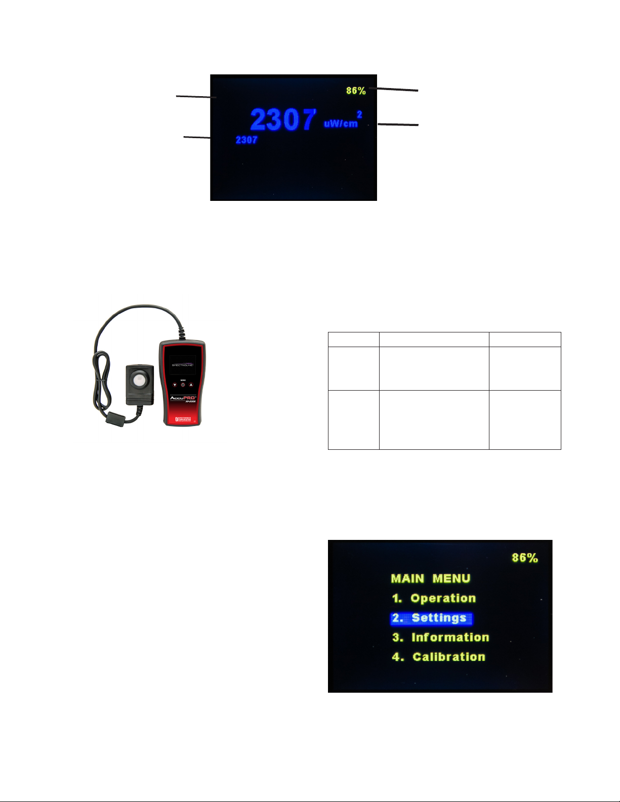
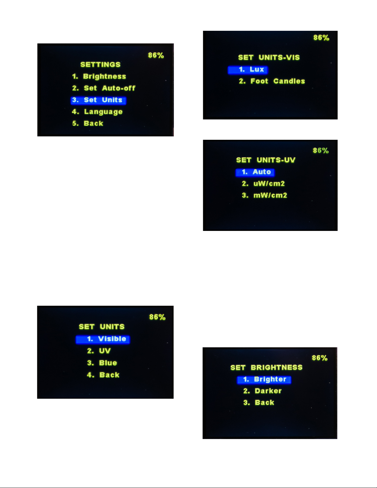
6. CUSTOMIZING SETTINGS
Press MENU, then press the DOWN arrow. Select the
SETTINGS option. Press MENU again to enter the
SETTINGS menu as shown below:
The SETTINGS menu contains the options displayed
below:
Operation Mode for Blue Light Sources
Blue light reading
Units
Blue light PEAK value
Battery indicator
Press and hold the MENU button to turn the meter ON.
The Boot Screen (below) will load, followed briefly by
the Information Screen. (See Section 7 for details about
the Information Screen).
7
Press UP or DOWN to highlight the feature to be
modified and MENU to access the next screen. Highlight
BACK and press MENU to return to OPERATION
mode.
6.1 CHANGING UNITS OF MEASUREMENT
The AccuPRO provides users the capability of setting
the default visible light unit of measure to either
foot-candles (fc) or Lux.
UV and blue light source intensity units will
autorange from µW/cm2to mW/cm2.
To adjust units, highlight and select SET UNITS from
the SETTINGS menu. Press MENU to move to the next
screen, as shown below. Vis (Visible), UV, and Blue (on
XP-4000 only) will be listed, along with the BACK
button to return to the previous screen.
Select the desired portion of the spectrum using MENU,
then use the arrow keys to select the desired units. The
following example displays the options for visible light:
The example below shows the available units for
ultraviolet and blue light:
Upon pressing MENU, a brief confirmation screen will
display (e.g., "Units set to Lux") before returning to the
main menu. Simply press MENU again to return to
Operation Mode which will display the new units.
6.2 ADJUSTING BRIGHTNESS
To change the brightness of the screen, enter the
SETTINGS menu. Select BRIGHTNESS. Press MENU
to access brightness settings and choose either
BRIGHTER or DARKER (see example below). When
selecting the level of brightness, consider the ambient
light conditions, user preferences, and battery
conservation.
Press the MENU button until desired brightness
level is attained. Press BACK to conrm and exit.

8
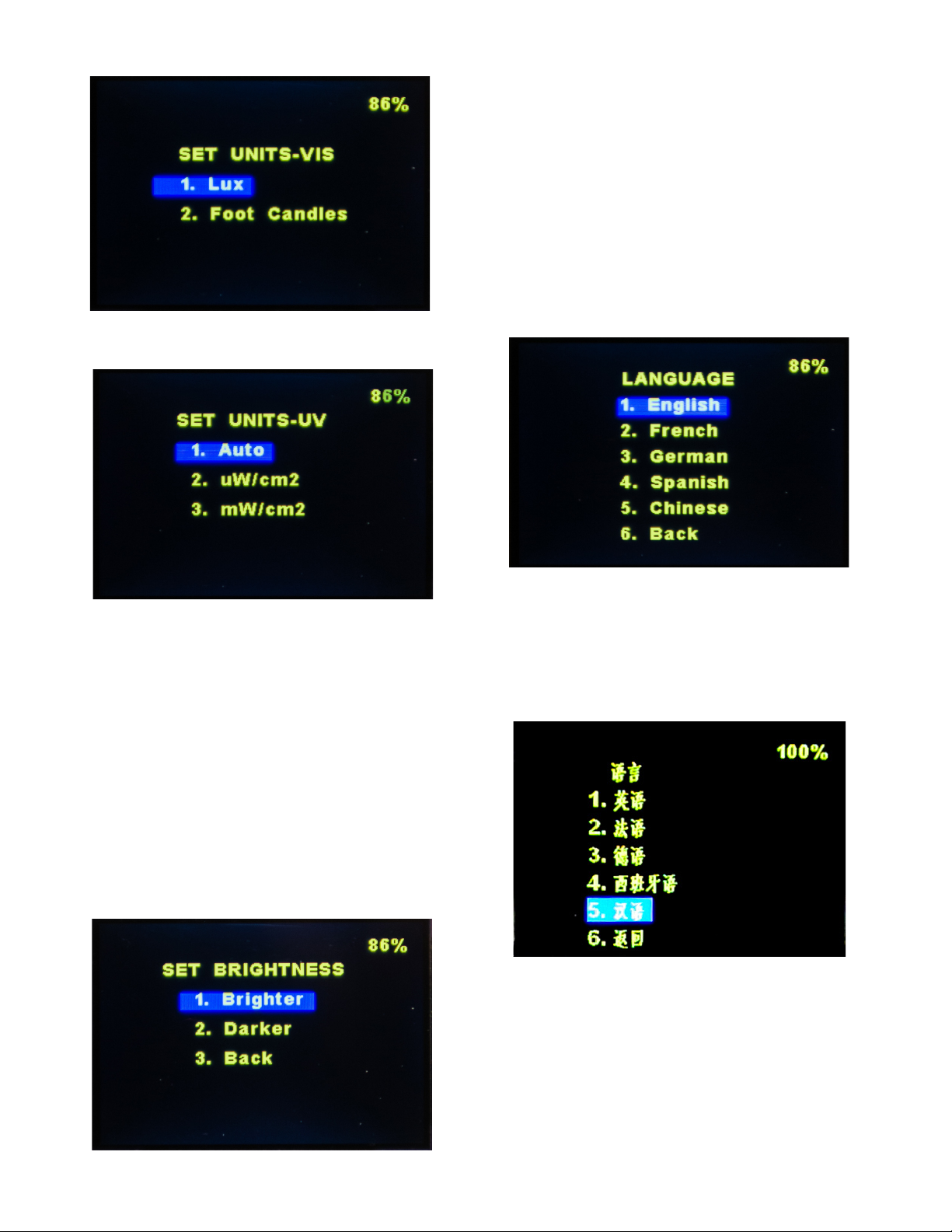
6.3 LANGUAGE OPTIONS
All interactive features and displays of the AccuPRO
and AccuPRO Plus are available in English, Spanish,
German, French, and Chinese. Enter the SETTINGS
menu and select the LANGUAGE option to enter the
selection menu displayed below. Upon selection of the
desired language, the language menu will refresh and
appear in the newly selected language format.
NOTE: Should the language accidentally be changed
to one which you cannot understand, the first (highest)
option on the menu will revert to English as seen
below.
Below is the same screen viewed in Chinese. The
numbers remain the same. In this event, press
UP until reaching option 1 then MENU to return to
English. The same is applicable to the other
languages, with the first option reverting to English.
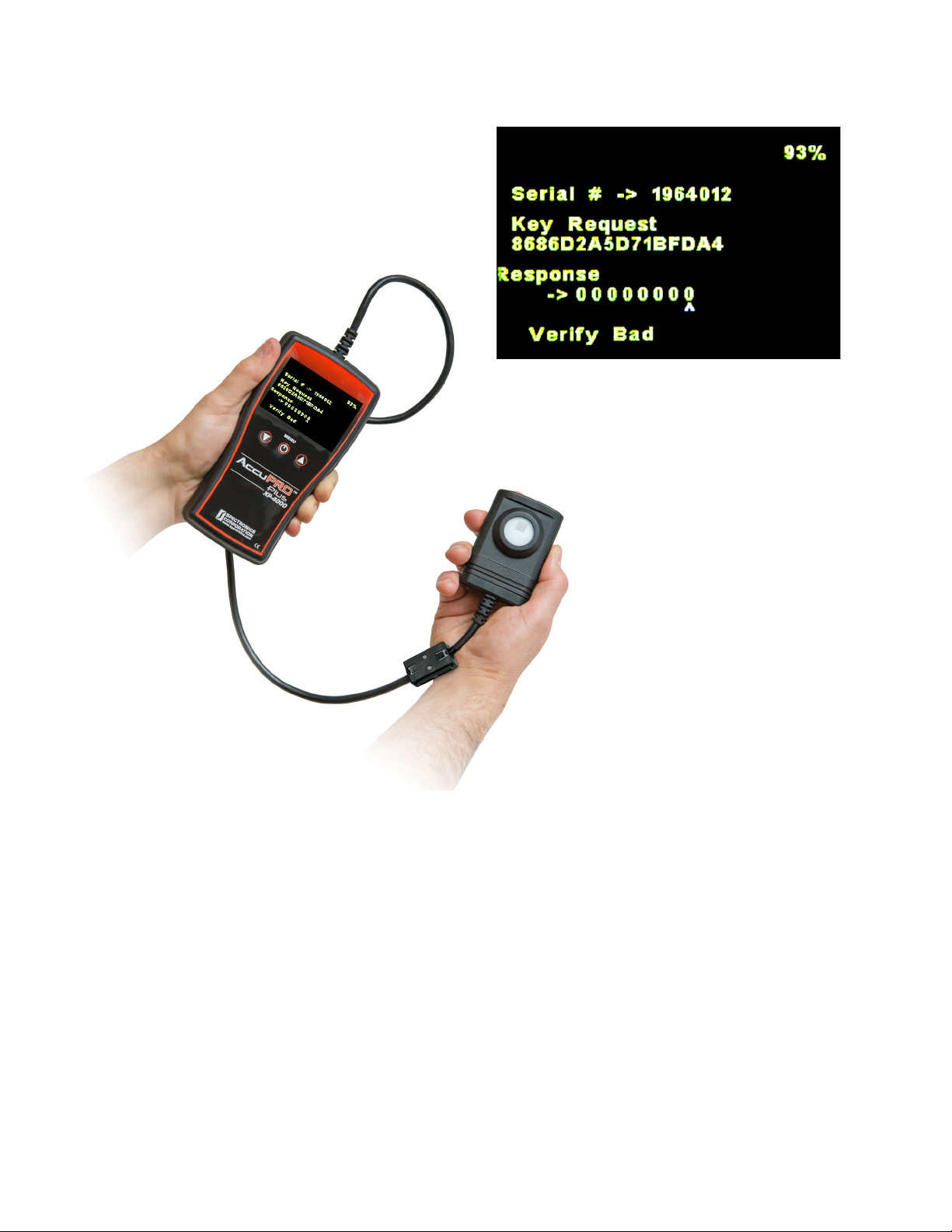
7. INFORMATION
The INFORMATION screen, accessed via the third
selection on the main menu, displays briefly when the
device is powered on, and can be viewed for as long
as desired through the menu option.
Important data including the serial number of your unit,
date of last calibration, and software version is
avaiable on the INFORMATION screen. This
information will differ between the example below and
your own unit.
To return to OPERATION Mode, select the BACK
option.
8. CALIBRATION
The fourth and final option on the Main Menu is
Calibration. Calibration requires a precise configuration,
and cannot be performed with the device alone. Contact
customer service at 1-866-230-7305 if you believe your
AccuPRO may require calibration.
There is no need to enter this menu under normal
circumstances. However, should you arrive on the
calibration screen shown below, simply press MENU
repeatedly to exit.
The languages and their corresponding numbers
match across all language settings. If you accidentally
happen to select a language difficult to understand
(for instance, Chinese), select Option Number 1 to
revert back to the default English language setting.
The same process is applicable to the other languages
in the selection.
The INFORMATION Screen can be accessed in the Main
Menu. By default, the INFORMATION Screen briey
displays during startup. To closely examine the data
on the INFORMATION Screen, select INFORMATION
from the Main Menu.
The serial number of your device, the date of your
device’s most recent calibration, and the software
version installed on your device is available on the
INFORMATION screen.
9
Zeroes will appear in the Response field each time
the MENU button is pressed. The text "Verify Bad"
will display (as shown below) and the device will then
automatically exit the calibration screen, returning to
the Main Menu by default.

10
THE INPUT OPTICS
The lambertian (cosine) response of the sensor head
is desirable for many measurement applications,
especially those where the angle from the source to
the detector is variable or those situations where the
angle from the source is ''extended,'' such as in the
measurement of a fluorescent lamp at distances
comparable to or shorter than its length. In the latter
case, the extended source provides radiation from
many angles, all of which must be properly ''weighted''
as to their effectiveness on the plane represented by
the sensor surface.
In actual practice, it is difficult to make a sensor
conform to the ideal response over the entire solid
angle of 2TT steradians. The sensor units of the
AccuPRO meter minimize this problem by being
outfitted with optimal transmission diffusing materials
for various spectral regions. These diffusion materials
are mounted close to the surface of the sensors so
that the oblique rays are not obstructed. The spectral
range is selected by adding an appropriate UV
interference filter within the optical stack before the
sensor cell assembly.
THE SENSOR CELL
Photovoltaic Operation
When a p-n junction is operated with no externally
applied voltage, it is considered to be operating in the
photovoltaic mode. Under this zero applied voltage
condition and low levels of incident light, the p-n
junction will generate a current proportional to the
light power incident on the active surface.
This photon-induced current, or photocurrent, will
divide between the diode parallel dynamic resistance
and the parallel load resistance. The dynamic
resistance is normally a high value and is an inverse
exponential function of forward voltage. The direction
of current flow will produce a voltage across the diode
that opposes the band-gap potential of the photodiode
junction, thus forward biasing it. As a result, the value
of the diode dynamic resistance (Rd) drops
exponentially as the irradiance increases and the
photo generated voltage is a quasilogarithmic function
of diode irradiance when the external load resistance
is considered. Another major disadvantage is that Rd
typically has a wide spread of values over different
production batches.
One way of achieving sufficiently low load resistance
and eliminating the effect of the diode parallel
resistance is to feed the photocurrent into the virtual
ground of an operational amplifier. The output voltage
is the result of the photocurrent being driven by the
amplifier through the feedback resistor and the input
impedance Rin = Rf/A where A is the open loop gain
and Rf the feedback resistor. This circuit has a linear
response and is low noise due to the almost complete
elimination of leakage current with the zero bias. This
results in a proportional voltage being presented to
the signal conditioning section of the electronics.
LIGHT
OPTICAL STAGE,
A/D CONVERSION,
PROGRAMMABLE
CIRCUITRY
MICROPROCESOR
CONTROL
GRAPHICAL
DISPLAY
SIGNAL PROCESSING
SENSOR CIRCUIT
9. THEORY OF OPERATION

11
10. WARRANTY, MAINTENANCE
AND BATTERY REPLACEMENT
10.1 WARRANTY
The warranty policy for the AccuPRO is provided
on the Certificate of Limited Warranty enclosed
separately with each unit.
NOTE: For assistance of any kind, including help
with a meter under warranty, contact the
Customer Service Department at Spectro-UV.
In the United States and Canada, call toll-free
1-866-230-7305. Include the model number,
serial number and date of purchase. If return of
the unit is deemed necessary, shipping
instructions will be provided. If an estimate of
charges for nonwarranty work or other service
work is required, a quote will be furnished upon
evaluation of the unit. Out-of-warranty service
work will not be performed without customer
approval.
10.2 PREVENTIVE MAINTENANCE
• Immediately clean all spilled materials from the
unit and wipe dry. If necessary, moisten a cloth
with soap and water to clean plastic surfaces
and the sensor head. The sensor surface
should be rinsed with ethanol to remove any
residual soap and/or organic contaminants.
• Whenever possible, avoid exposure or use in
areas that are subject to temperature and
humidity extremes, vibration or mechanical
shock, dust or corrosive fumes, or strong
electrical or electromagnetic interference.
• It is recommended that the unit be returned to
the factory or a recognized Spectroline
AccuPRO calibration service center for a
complete overall check and recalibration at
least every 6 or 12 months, depending on your
facility's Standard Operating Procedures.
Before returning the units to our factory, contact
the Customer Service Department for shipping
instructions.
• When the AccuPRO is not in use, store it in a
location free from temperature extremes, dust
or corrosive fumes, and vibration or mechanical
shock.
• If storing for an extended period, place the
AccuPRO in its carrying case.
10.3 BATTERY SAFETY AND CHARGING
1. The AccuPRO radiometer must be charged
overnight or for at least 8 hours when the
battery is replaced or after a battery reset
(removal and re-installation of the same battery).
2. CAUTION: Do not use alkaline batteries in the
AccuPRO as they may explode causing damage
to the circuitry and possibly the operators. Only
use the 700mAh,1.2V rechargeable batteries
provided with the AccuPRO and available from
Spectroline®(P/N: 129227).
3. The AccuPRO should be charged with the
power OFF. Charging the unit for long periods
while operating is not advised because it will
cause the charging/display circuit to malfunction.
Should this take place, the unit will need to
charge for 8+ hours while turned off for the
circuit to reset.
4. The battery indicator will turn red at 30%. It is
recommended that the AccuPRO be powered
down and charged when it reaches this level. At
10% battery life, the unit will automatically
power down.
5. Disconnect the charger from the meter when
not in use.
6. While charging, it is recommended to have the
device turned OFF.
7. Off-State Discharge Rate: The AccuPRO™
battery will naturally discharge approximately
3-4% per day – even when the unit is turned off.
Be sure to keep an accurate and up-to-date
charging schedule.
CHARGING
• Plug battery charger into AC power outlet.
• Firmly connect charger to port located on the
right side of the unit, just below the screen.
• Battery percentage, located in the top right
corner of the screen, will begin to increase as
the unit charges. It might be necessary to
change screens for the battery readout to
update.
• A full charge will take 8 hours and is good for
approximately 6 hours of operation.
• While charging, it is recommended to have the
device turned OFF.

12

13
MANUEL D’UTILISATION
7/20 AM15002ML-2
IMPRIMÉ AUX ÉTATS-UNIS
Photomètre / Radiomètre AccuPRO™
www.Spectro-UV.com
4 Dubon Ct., Farmingdale, NY 11735
866-230-7305
XP-4000 & XP-2000
ENG - 1 FR - 9 ES - 17 DE - 25

14
CONTENTS
1. INTRODUCTION
1.1 GÉNÉRALITÉS..................................................................................................................................…11
1.2 FONCTIONNALITÉS .....................................................................................................................…11
1.3 PRÉCAUTIONS..............................................................................................................................11
2. CARACTÉRISTIQUES GÉNÉRALES
2.1 PIÈCES DE RECHANGE ET COMPOSANTS AccuPRO .................................................................12
2.2 CARACTÉRISTIQUESTECHNIQUES................................................................................................12
2.3 CARACTÉRISTIQUES ÉLECTRIQUES.........................................................................................…12
2.4 PRÉCISION OPTIQUE ET ÉTALONNAGE................................................................................12
2.5 CARACTÉRISTIQUESENVIRONNEMENTALES................................................................................12
3. BOUTONS ET COMMANDES 13
4.FONCTIONNEMENT – GUIDE PRATIQUE................................................................................13-14
5.UTILISATION DE l’AccuPRO
5.1 MARCHE/ARRÊT............................................................................................................................14
5.2 MODE FONCTIONNEMENT..........................................................................................................…14
5.3 VALEURS MESURÉES PAR LE CAPTEUR ET VALEUR MAXI.......................................................14
5.4 LONGUEURS D'ONDES & PLAGES D’UTILISATION DU CAPTEUR ..............................................14
6. PERSONNALISATION DES PARAMÈTRES
6.1. POUR CHANGER D’UNITÉ DE MESURE....................................................................................…15
6.2 RÉGLAGE DE LA LUMINOSITÉ.....................................................................................................…15
6.3 LANGUE D’AFFICHAGE..........................................................................................................….16
7.INFORMATON 16
8.ÉTALONNAGE 16-17
9.PRINCIPE DE FONCTIONNEMENT............................………………………..…................18
10. GARANTIE, ENTRETIEN ET RÉPARATIONS
10.1 GARANTIE........................................................................................................................................19
10.2 ENTRETIEN PRÉVENTIF..................................................................................................................19
10.3 RECHARGE DES PILES...................................................................................................................19
© 2015 Spectro-UV. Tous droits réservés. Aucune partie du présent document ne peut être reproduite ou transmise sous
quelque forme ou par quelque moyen que ce soit, électronique ou mécanique, y compris par photocopie ou enregistrement, ni
par un système de stockage et recherche documentaire, sans la permission écrite du propriétaire des droits d'auteur. Pour les
demandes, s’adresser à Spectro-UV. .

15
1. INTRODUCTION
1.1 GÉNÉRALITÉS
Les détecteurs AccuPRO™ et AccuPRO Plus sont
équipés d’un afficheur numérique géré par micro-
processeur qui est étalonné pour mesurer avec
précision et afficher les intensités lumineuses.
Les détecteurs XP-2000 et XP-4000, avec leurs
capteurs, sont compatibles avec la lumière ultraviolette,
bleue (XP-4000 uniquement) et blanche ; ils sont
destinés à effectuer des contrôles par ressuage (essais
non-destructifs).
Le détecteur XP-4000 est étalonné pour des sources
lumineuses HID (lumière ultraviolette, visible et bleue). Il
mesure les valeurs d’UV-A et de lumière bleue entre 0
et 100 mW/cm2, et de lumière visible entre 0 et 5300
lux ; sa fonctionnalité MAXI, qui permet d’identifier
facilement le point le plus fort d’une source lumineuse,
est utile pour les essais non destructifs.
Les détecteurs modèles XP-2000 et XP-4000 sont
munis d’un écran à cristaux liquides à 4 chiffres
(maximum) à échelle de sensibilité automatique.
Le capteur a une impédance électrique faible, ce qui
rend sa linéarité très supérieure à celle des autres
radiomètres de tarifs comparables. Les capteurs sont
protégés par une fenêtre spéciale diffuseur-capteur qui
contribue à éviter la dégradation des filtres et assure
une réponse lambertienne ou en cosinus correcte.
1.2 FONCTIONNALITÉS
Les détecteurs sont compacts, légers et fonctionnent
sur piles, ce qui les rend d’emploi pratique en atelier,
sur le terrain ou partout où des mesures sont
nécessaires.
LOGICIEL
•Interface conviviale à trois boutons
•Précision : deux décimales
•Des touches de réglage permettent la sélection des
paramètres d'affichage à tous les niveaux de
fonctionnement.
•Écran intuitif
•Réinitialisation de la valeur MAXI par simple appui sur
une seule touche
•La flèche HAUT permet d’alterner l’affichage entre les
modes lumière ultraviolette, visible et bleue
MATÉRIEL
•Capteur unique tout-en-un avec câble de 90 cm
•Grand écran à cristaux liquides, facile à lire
•Le filtre anti-interférences passe-bande supérieur
fournit une excellente réponse en cosinus
•Pour mettre le détecteur en fonctionnement ou
l’éteindre, appuyer sur le bouton MENU et maintenir
l’appui
•Alimentation : quatre piles rechargeables type LR03
(AAA) au nickel/hydrure métallique (chargeur secteur
livré avec l’appareil)
1.3 PRÉCAUTIONS
•Ce radiomètre AccuPRO a été soigneusement étudié
pour éviter à son utilisateur les chocs accidentels
pendant une utilisation correcte. Cependant, aucune
précaution technique ne peut assurer la sécurité d’un
instrument utilisé sans précaution. De ce fait, les
recommandations présentées dans ce manuel doivent
être lues attentivement, et bien comprises, avant
d’effectuer une mesure. Le non-respect des
instructions risque d’entraîner des effets néfastes
graves.
•Le capteur UV est conçu pour des régions du spectre,
notamment la plage ultraviolette, qui peuvent être
dangereuses pour les yeux ou la peau. Des lunettes et
des masques de protection contre les ultraviolets sont
disponibles auprès de Spectro-UV, pour les cas où
une exposition aux UV est inévitable.
•Ne pas laisser la tête du capteur exposée à la source
lumineuse plus longtemps que le temps nécessaire
aux mesures. Une exposition prolongée risquerait de
provoquer un vieillissement prématuré du capteur,
nécessitant des réétalonnages plus fréquents pour
maintenir la précision des mesures.
•Voir le chapitre 10 : Garantie, entretien et
remplacement des piles. .
2. COMPOSANT DES
DÉTECTEURS AccuPRO
• Déballer les composants et vérifier qu'ils n'ont pas
été endommagés pendant le transport. Conserver
le carton et les matériaux d'emballage pour le
rangement ou un éventuel envoi des composants
de l'AccuPRO.
• S’assurer du bon état du câble du capteur, et de sa
bonne fixation au détecteur.
• Vérifier les performances de l’appareil le plus tôt
possible. En cas de dommage constaté, prévenir le
transporteur et le fournisseur immédiatement ; ne
pas utiliser l’appareil. Le détecteur peut fonctionner
pendant la charge des piles.
Voir, en page suivante, les références des pièces
livrées avec l’appareil et disponibles en rechange,
ainsi que des images de chacun des composants.

16
2.2CARACTÉRISTIQUES TECHNIQUES
2.3 CARACTÉRISTIQUES ÉLECTRIQUES
Une charge complète des quatre piles au nickel/
hydrure métallique, réalisée avec le chargeur secteur
livré, nécessite 6 heures, et permet le fonctionnement
de l’appareil pendant 4 h environ.
2.4 OPTICAL ACCURACY AND CALIBRATION
Les boîtiers afficheurs AccuPRO XP-2000 et XP-4000,
combinés à un unique capteur polyvalent, peuvent
mesurer l'ultraviolet et la lumière visible. Le modèle
AccuPRO™ Plus (XP-4000) mesure aussi la lumière
bleue. Les détecteurs, qui disposent d’une
fonctionnalité MAXI par simple appui sur une touche,
fournissent des mesures précises pour toutes les
longueurs d'ondes mesurées. L'afficheur à cristaux
liquides a une linéarité de ±0,2 %, le capteur envoyant
les données de correction de linéarités à l’afficheur
pendant la mise en fonctionnement initiale. Pour
assurer des résultats uniformes, les capteurs sont
conçus avec des filtres passe-bandes supérieurs, et
les optiques sont montées en salle blanche ISO 5
(classe 100). Pour une couverture spectrale précise,
ces filtres anti-interférences de haute qualité résistent
efficacement à la dégradation. Pour des données
d’étalonnage supplémentaires, voir le chapitre 8.
En cas de nécessité de refaire un étalonnage,
prendre contact avec Spectro-UV au +1-866-230-
7305.
DIMENSIONS
Pièce Longueur Largeur Profondeur Poids
Boîtier
acheur
15,2 cm 7,6 cm 2,5cm 227 gm
Capteur 7,6 cm 5,1 cm 1,25 cm 158,7gm
2.1 PIÈCES DE RECHANGE AccuPRO™
Détecteur AccuPRO™ avec capteur
multi-longueurs d’ondes
XP-2000 (AccuPRO) et XP-4000
(AccuPRO Plus)
XCC-200
Piles type LR03 (AAA) rechargeables au
nickel/hydrure métallique (4)
Livrées avec l’appareil.
Chargeur secteur
(La fiche représentée est celle pour
l’Amérique du Nord. Voir la liste complète
au chapitre Pièces de rechange.)
COMPOSANTS ET PIÈCES DE RECHANGE
Référence Description
XP-2000 Radiomètre/photomètre AccuPRO à capteur
double (UV-A/VIS) à écran multi-langues
XP-4000 Radiomètre/photomètre AccuPRO Plus à
capteur 3 en 1 (UV-A/VIS/bleue) et écran multi-
langues, livré avec 4 piles type LR03 (AAA)
rechargeables au nickel/hydrure métallique, un
chargeur secteur et un étui de transport (100-120
V/50-50 Hz)
XCC-200 Étui de transport souple
XP-2000/F XP-2000 (230 V/50 Hz avec fiche Europe)
XP-2000/FB XP-2000 avec fiche UK (230 V/50 Hz)
XP-2000/FA XP-2000 avec fiche Australie/Chine
(220-240 V/50 Hz)
XP-4000/F XP-4000 avec fiche Europe (230 V/50 Hz)
XP-400/FB XP-4000 avec fiche UK (230 V/50 Hz)
XP-4000/FA XP-4000 with Australia/China Plug
(220-240V/50Hz)
Chargeur secteur avec fiche Amérique du Nord
(120 V/60 Hz)
Chargeur secteur avec fiche Europe
(230 V/50 Hz)
Chargeur secteur avec fiche UK (230 V/50 Hz)
Chargeur secteur avec fiche Australie / Chine
(220-240 V/50 Hz)
Étui de transport souple
17
2.5 CARACTÉRISTIQUES ENVIRONNEMENTALES
Les détecteurs de la série AccuPRO sont étudiés pour être surs dans les conditions suivantes :
•Utilisation à l’intérieur ;
•Altitude maximale : 2000 m ;
•Température : 5 à 40 °C ;
•Humidité relative maximale : 80 % jusqu'à 31 °C, puis diminution linéaire jusqu’à une humidité relative de 50 % à
40 °C ;
•Fluctuations maximales de la tension secteur : ±10 % de la tension nominale ;
•Catégorie d'installation : II ;
•Degré de pollution : 2.
3.BOUTONS ET COMMANDES
• Les boîtiers afficheurs disposent de trois touches tactiles permettant un accès facile à toutes les fonctionnalités.
• Un appui maintenu sur la touche MENU met le détecteur en fonctionnement ou l’éteint ; cette touche se combine
également aux deux flèches pour activer des fonctions intuitives.
•Les flèches HAUT et BAS, de part et d’autre de la touche MENU, donnent accès à toutes les fonctionnalités et
écrans. Les éléments de menu sélectionnés sont entourés en surbrillance bleue ; pour les valider, il suffit
d’appuyer sur la touche MENU, comme la touche « Entrée » d’un clavier d’ordinateur.
• En mode FONCTIONNEMENT, un appui sur la flèche BAS remet à zéro la valeur MAXI (plus haute valeur
d’éclairement lumineux enregistrée) pour les sources de lumière visible, ultraviolette et, le cas échéant, bleue.
Dans le cas de l’AccuPRO Plus (XP-4000), la flèche HAUT fait alterner entre les affichages de lumière visible,
ultraviolette et bleue.
• Pour éteindre un détecteur, appuyer sur le bouton MENU en mode FONCTIONNEMENT et maintenir l’appui..
• Quel que soit le menu, la mise en surbrillance du bouton RETOUR et sa sélection ramènent l’utilisateur à l’écran
précédent sans qu’aucun changement ne soit pris en compte.
Flèche BAS
Réinitialisation de
la valeur MAXI
Touche MENU
Réglage, validation des sélections
Flèche HAUT
Fait alterner les
modes VIS/UV ou
bleue. (XP-4000)
uniquement)
4. FONCTIONNEMENT – GUIDE PRATIQUE
1. Pour mettre l’appareil en fonctionnement, appuyer sur la touche MENU pendant deux secondes. Il
est recommandé de charger l’appareil à fond avant emploi (voir le chapitre 10.3).
2. L’écran de chargement de la série AccuPRO s’affiche pendant le lancement de l’appareil, et affiche
brièvement les informations accessibles par l’intermédiaire du menu Réglages (chapitre 6).
3. Après le chargement, l’appareil passe directement en mode Fonctionnement, et affiche les valeurs
de lumière ultraviolette et visible par défaut.
3a. Pour afficher les niveaux de lumière bleue avec l’AccuPRO Plus (XP-4000), appuyer sur la
touche HAUT
4. Pour changer les paramètres d’affichage, appuyer sur MENU, puis sur la flèche BAS et
sélectionner l’option RÉGLAGES. Une fois celle-ci sélectionnée, appuyer sur MENU pour passer à
l’écran de réglage (on trouvera les détails au chapitre RÉGLAGES).
5. Éclairer le capteur directement.
6. L’appareil affiche instantanément le niveau de lumière pour chaque longueur d'onde (intensité/unité
de surface).
7. Pour éteindre l’appareil, appuyer sur le bouton MENU en mode Fonctionnement et maintenir l’appui
pendant 2 secondes. L’écran et le capteur s’éteignent. Attendre un minimum de 30 secondes après

18
5. UTILISATION de l’AccuPRO
5.1 MARCHE/ARRÊT
Pour mettre le détecteur en fonctionnement, appuyer
sur le bouton MENU et maintenir l’appui . L’écran de
chargement (ci-dessous) s’affiche, suivi par l’écran
d’informations (chapitre 7). Charger l’appareil à fond
avant utilisation.
5.2 MODE FONCTIONNEMENT
À la mise en fonctionnement, l’AccuPRO passe
automatiquement en mode Fonctionnement et affiche
les valeurs de longueur d’onde en lumière blanche
(555 nm) et en ultraviolets (365 nm). Dans le cas de
l’AccuPRO Plus (XP-4000), la flèche HAUT fait
alterner l’affichage entre les valeurs de lumière
visible, ultraviolette et bleue
5.3 VALEURS MESURÉES PAR LE CAPTEUR
ET VALEUR MAXI
Les déplacements éventuels de la tête de capteur
font varier la valeur mesurée, en fonction de son
niveau d’éclairage ; la valeur la plus élevée est
enregistrée automatiquement et s’affiche en bas et à
gauche de l’écran. Les illustrations des pages 5 et 6
indiquent les détails de chaque écran.
l’arrêt avant de redémarrer l’appareil en appuyant sur la touche MENU et en maintenant l’appui
pendant 2 secondes. L’AccuPRO ne s’arrête qu’à partir du mode Fonctionnement, et d’aucun autre
menu.
8. Pour conserver les piles et préserver la sensibilité du capteur, utiliser la fonction « Arrêt automatique »
du menu Réglages. (voir le Chapitre 6).
Mode de fonctionnement pour les sources de lumière ultraviolette et visible
Valeur UV-A
Valeur lumière
visible
Unités
Valeur UV MAXI
Témoin de piles
Valeur lumière
visible MAXI
Mode Fonctionnement pour sources de lumière bleue
Valeur de lumière bleue
Unités
Valeur MAXI de lumière bleue
Témoin de piles

19
Braquer la lumière à mesurer directement sur le
capteur pour obtenir les mesures les plus précises.
La valeur MAXI garde en mémoire la luminosité
maximale enregistrée depuis la dernière remise à
zéro. Il suffit d’appuyer sur la flèche BAS, en mode
Fonctionnement, pour remettre à zéro la valeur MAXI
pour toutes les lumières mesurées par l’appareil
(visible, ultraviolette et lumière bleue le cas échéant).
5.4 SLONGUEURS D'ONDES & PLAGES
D’UTILISATION DU CAPTEUR
Le capteur relié à l’AccuPRO mesure les valeurs
d’ultraviolet UV-A (365 nm) et de lumière visible (555
nm). L’AccuPRO Plus mesure, en plus, la lumière
bleue à une longueur d'onde de 450 nm.
Au cas où des valeurs mesurés dépasseraient les
valeurs ci-dessous dans les spectres couverts,
l’écran affiche « XXXX » :
Modèle N° Longueurs d'ondes
enregistrées
Plage
XP-2000 UV-A/VIS
0_100 mW/cm2
0_15,300 Lux
0400 fc
XP-4000 UV-A/VIS/bleue
Éclairement énergétique
UV-A (365 nm)
Éclairement visible
(555 nm)
Bleue(450nm)
0_100 mW/cm2
0_15,300 Lux
0_400 fc
0_100 mW/cm2
6. PERSONNALISATION DES
PARAMÈTRES
Appuyer sur MENU puis sur la flèche BAS pour
sélectionner l’option RÉGLAGES. Rappuyer sur
MENU pour afficher l’interface RÉGLAGES comme
indiqué ci-dessous :
Le menu principal de réglage contient les sous-menus
ci-dessous :
Appuyer sur HAUT ou BAS pour sélectionner la fonction
à changer, puis sur MENU pour passer à l'écran suivant,
ou sélectionner RETOUR et appuyer sur MENU pour
revenir au mode FONCTIONNEMENT.
6.1 POUR CHANGER D’UNITÉS DE MESURE
Les AccuPRO permettent à leur utilisateur de choisir
l’unité par défaut de mesure de lumière visible (lux ou
pied-bougie (fc)).
La sélection des unités d'intensité UV et de lumière
bleue est automatique, du μW/cm2 au mW/cm2 au W/
cm2.
Sélectionner la partie du spectre désirée à l’aide de
MENU, puis sélectionner les unités désirées à l’aide des
touches fléchées. L'exemple ci-dessous présente les
options pour la lumière visible :
Sélectionner la partie du spectre désirée à l’aide de
MENU, puis sélectionner les unités désirées à l’aide des
touches fléchées. L'exemple ci-dessous présente les
options pour la lumière visible :
20
L’exemple ci-dessous présente les unités disponibles
pour l’ultraviolet et la lumière bleue :
Après avoir appuyé sur MENU, une brève confirmation
s’affiche (par ex. « Unités en lux » avant le retour de
l’écran au menu principal. Il suffit alors d’appuyer sur
MENU pour revenir au menu Fonctionnement qui
affiche les unités choisies.
6.2 RÉGLAGE DE LA LUMINOSITÉ
Pour modifier la luminosité de l’écran, aller dans le
menu Réglages. La première option, qui se
sélectionne automatiquement est « RÉGLER LA
LUMINOSITÉ ». Appuyer sur MENU pour accéder au
réglage de luminosité et choisir PLUS CLAIR ou PLUS
FONCÉ (voir l’exemple ci-dessous), en fonction des
conditions ambiantes, des préférences de l'utilisateur
et (ou) des besoins de conservation des piles.
6.3 LANGUE D’AFFICHAGE
Toutes les fonctionnalités interactives et les écrans
tant de l’AccuPRO que de l’AccuPRO Plus sont
disponibles en anglais, en espagnol, en allemand, en
français et en chinois. Entrer dans le menu
RÉGLAGES et sélectionner l’option LANGUE pour
passer au choix ci-dessous. Dès la sélection de la
langue désirée, le menu LANGUE s'actualise et
s’affiche dans la langue sélectionnée.
NOTA : En cas de passage accidentel à une langue
non comprise, le premier choix (en haut) du menu
ramène à l’anglais (voir ci-dessous).
.
Ci-dessous, le même écran en chinois. Les numéros
ne changeant pas, dans ce cas, appuyer sur la flèche
HAUT jusqu’à l’option 1, puis sur MENU pour revenir
à l’anglais. La même règle est valable pour les autres
langues, la première option ramenant toujours
à l’anglais.
This manual suits for next models
1
Table of contents
Languages:
Other Spectro-UV Measuring Instrument manuals


