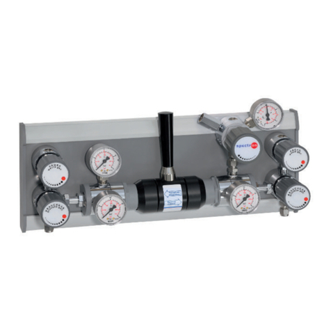
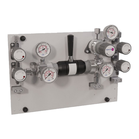
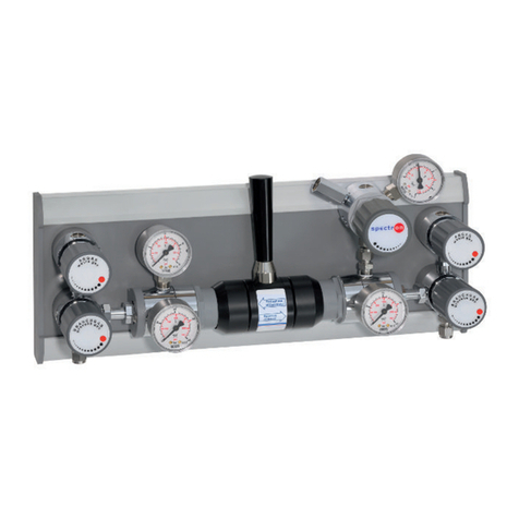
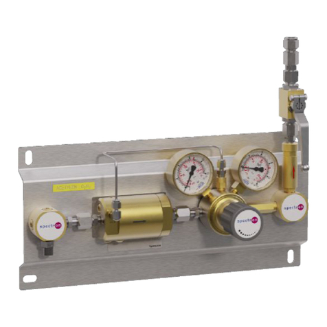
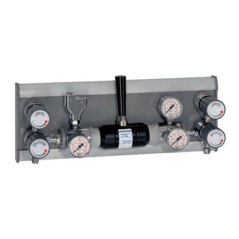
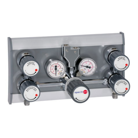
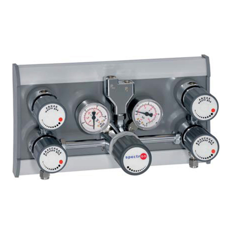
Spectron BM55-2A User manual

User manual
Pressure control panel
BM55-2A
05/2021

Table of contents Spectron Gas Control Systems GmbH
ii GES_BM55-2A_0521
Table of contents
1 Introduction.................................................................................................................................................. 4
2 Description................................................................................................................................................... 5
2.1 Intended use ......................................................................................................................................... 5
2.2 Misuse .................................................................................................................................................. 5
2.3 Identification / label ............................................................................................................................... 5
2.4 Environment.......................................................................................................................................... 6
2.4.1 Temperatures............................................................................................................................. 6
2.4.2 Degree of cleanliness ................................................................................................................ 6
2.4.3 Emissions................................................................................................................................... 6
2.5 Standards and laws .............................................................................................................................. 6
3 Safety............................................................................................................................................................ 8
3.1 Basic information on the safety instructions ......................................................................................... 8
3.2 Safety instructions ................................................................................................................................ 9
3.3 Emergencies and safety devices .......................................................................................................... 11
3.4 Qualification of the operating and maintenance personnel................................................................... 11
4 Design and function .................................................................................................................................... 13
4.1 Design................................................................................................................................................... 13
4.2 Functional description........................................................................................................................... 14
4.3 Technical data ...................................................................................................................................... 15
4.4 Boundaries and interfaces .................................................................................................................... 15
5 Installation.................................................................................................................................................... 16
5.1 General information .............................................................................................................................. 16
5.2 Installation work .................................................................................................................................... 16
5.2.1 Installation.................................................................................................................................. 16
5.2.2 Connecting the incoming and outgoing lines ............................................................................. 18
5.3 Checking the system ............................................................................................................................ 18
5.3.1 Pressure test with purge gas ..................................................................................................... 18
5.3.2 Helium leak test ......................................................................................................................... 18
6 Commissioning............................................................................................................................................ 20
6.1 Preparations for commissioning ........................................................................................................... 20
6.2 Procedure for commissioning ............................................................................................................... 20
6.2.1 Connecting the process gas source........................................................................................... 20
6.2.2 Flushing in the process gas to the process................................................................................ 21
7 Operation...................................................................................................................................................... 22
7.1 General information on operation ......................................................................................................... 22
7.2 Gas supply interruption......................................................................................................................... 22
7.2.1 Interruptions to operation for less than 48 hours ....................................................................... 22
7.2.2 Interruptions to operation for more than 48 hours...................................................................... 22
7.2.3 Putting the pressure control panel into a safe condition ............................................................ 22
7.3 Exchanging the process gas source..................................................................................................... 22
8 Maintenance, cleaning and repairs............................................................................................................ 25
8.1 General information on maintenance.................................................................................................... 25
8.2 Flushing the process gas into the pressure control panel .................................................................... 26
8.3 Regular maintenance work and cleaning.............................................................................................. 27
Spectron Gas Control Systems GmbH Table of contents
GES_BM55-2A_0521 iii
9 Repair ........................................................................................................................................................... 28
9.1 General information on repair work ...................................................................................................... 28
9.2 Troubleshooting and fault rectification .................................................................................................. 29
10 Decommissioning and recommissioning ................................................................................................. 30
10.1 Decommissioning ................................................................................................................................. 30
10.2 Recommissioning ................................................................................................................................. 30
11 Dismantling and disposal ........................................................................................................................... 31
11.1 General information on dismantling ...................................................................................................... 31
11.2 Returns ................................................................................................................................................. 31
11.3 Disposal ................................................................................................................................................ 32

1 | Introduction Spectron Gas Control Systems GmbH
4 GES_BM55-2A_0521
1 Introduction
This user manual is the original user manual for the Pressure control panel BM55-2A from
Spectron Gas Control Systems GmbH, referred to as Spectron.
The user manual is intended to facilitate correct and safe operation for the operating firm, and to
warn against misuse. It is intended for the qualified personnel and the operator of the facility.
WARNING
Incorrect operation
Incorrect operation of the system, e.g. due to instruction errors, can lead to personal injury or
damage to the system.
a) Access to the user manual by the operating and maintenance personnel must be absolutely
ensured at all times.
b) A copy of the system documentation including the user manual must therefore be kept
either on the system or in a suitable and accessible location.
This user manual contains information protected by copyright law. It must not be photocopied,
reproduced, translated or copied onto data carriers, either in full or in part, without prior author-
isation. Spectron retains all further rights.

Spectron Gas Control Systems GmbH Description | 2
GES_BM55-2A_0521 5
2 Description
2.1 Intended use
The intended use of the Pressure control panel BM55-2A is the expansion of a gas from a gas
source and the distribution of the gas with adjustable outlet pressure.
Pressure control panels of type BM55-2A are suitable for flammable gases, non-flammable
gases, non-corrosive gases and for oxygen up to gas quality 6.0.
The permissible gas types and pressure ranges are each specified on the label (see "Identifica-
tion / label [}5]").
The 2A pressure control panels are two-sided pressure control panels with a switching mechan-
ism (2A). The switching mechanism switches automatically from the side that is currently in op-
eration to the reserve side when the gas supply situation requires it.
The equipment versions of the Pressure control panels without electrical components may be
used in an explosion hazard zone as they do not have separate ignition sources (ignition hazard
assessment according to DIN EN ISO 80079-36).
Pressure control panels with electrical components that are suitable for use in an explosion haz-
ard zone are marked on the label according to EU Directive 2014/34/EU.
To be able to use the Pressure control panels as intended, all persons working with it must
comply with the specifications of the relevant user manual.
The area in which hazards can occur when used as intended is the area around the Pressure
control panels. The danger zone changes depending on the system status and use.
2.2 Misuse
Any improper use constitutes misuse. Pressure control panels may only be used for the spe-
cified gases and in the specified pressure range. Pressure control panels with electrical com-
ponents without marking according to EU Directive 2014/34/EU may not be used in an explo-
sion hazard zone.
Furthermore, the following operating conditions are regarded as misuse:
– Use for gases in their liquid phase
– Failure to carry out inspection and maintenance work
– Pressurisation in reverse (opposite to the flow direction)
– Operation with gases that are not specified on the label
– Operation outside the permissible technical limit values
– Failure to heed and comply with any applicable legal regulations and other provisions
– Non-observance of the user manual
– Failure to heed the information on the label and in the product data sheet
2.3 Identification / label
The label is located on the on the mounting plate of the Pressure control panel.
The label provides the following details:
Details Example
Project number PROJECT
Article description BM55-2A-200-10-M-M-…
Inlet pressure P1 200 bar
Outlet pressure P2 10 bar

2 | Description Spectron Gas Control Systems GmbH
6 GES_BM55-2A_0521
Gas type GAS TYPE
2.4 Environment
2.4.1 Temperatures
Normal temperatures expected in a production area are assumed when operating the system:
-20°C to +60°C.
The air humidity must be below 60 % rel. humidity to prevent condensation. The operating tem-
perature depends on the gas used.
2.4.2 Degree of cleanliness
Access to the system and to the escape and rescue routes must not be blocked.
The product should be kept clean (dust-free).
A suitable purge gas must be used, taking into account the quality and properties of the process
gas.
Compressed air must be used for the control air at least class 5 according to ISO 8573-1.
2.4.3 Emissions
The A-rated sound pressure level does not exceed the value of 70 dB(A). It is not necessary to
wear hearing protection.
The waste gas line or a burst disc line must not end in areas where the escaping process gas
poses a hazard to persons or the environment.
Further emissions in the form of vibrations, radiation, vapours, dusts and waste water do not oc-
cur in the regular operation of the product.
2.5 Standards and laws
The design and construction of the Pressure control panel is subject to the following standards
and directives:
2006/42/EC Machinery Directive
2014/68/EU Pressure Equipment Directive
2014/34/EU ATEX directives
DIN EN ISO 12100:2010 Safety of Machinery
Safety data sheet for the gases used Process gas and auxiliary media
Various additional laws, regulations and guidelines must be complied with when handling pres-
surised gases. Find out about the laws, regulations and guidelines that apply in your location.
BetrSichV Betriebssicherheitsverordnung (Industrial
health and safety ordinance)
ProdSG Produktsicherheitsgesetz (Product Safety Law)
GefStoffV Gefahrstoffverordnung (Hazardous Substances
Ordinance)
TRGS 400, 407, 500, 720, 721, 722, 727,
745,746
Technische Regeln Betriebssicherheit (Tech-
nical Regulations on Operational Safety)
TRBS 1111, 2152, 3145, 3146 Technische Regeln Betriebssicherheit (Tech-
nical Regulations on Operational Safety)

Spectron Gas Control Systems GmbH Description | 2
GES_BM55-2A_0521 7
DGUV Regulation 1 German Trade Association Principles of Pre-
vention
DGUV Rule 113-001 German Trade Association Rules on Explosion
Protection
EIGA documents

3 | Safety Spectron Gas Control Systems GmbH
8 GES_BM55-2A_0521
3 Safety
3.1 Basic information on the safety instructions
The product complies with the recognised technical regulations. Nevertheless, knowledge of the
media used and their dangers as well as basic knowledge of the pressure control panel are pre-
requisites for safe and accident-free operation.
The user manual must be read and understood by every user. Instruction must be documented
in writing.
The safety instructions are to be regarded as a supplement to the applicable accident preven-
tion regulations and laws. Existing accident prevention regulations and laws must be observed
in all cases.
NOTICE
Hazards from the operating environment of the system can lead to injuries to persons.
a) No changes may be made to the system which result in a change in function.
b) It is not possible to outline and cover in this manual all hazards arising from the environment
or unforeseeable operating conditions of the system.
In the Safety Instructions chapter:
– Users are informed regarding hazards, residual risks and measures for risk reduction.
– The presentation of the safety instructions and the symbols is explained.
– Basic safety instructions to be observed in general are listed. Specific safety instructions are
listed in the relevant chapters.
DANGER
DANGER indicates an imminent danger. If not avoided, death or extremely serious injur-
ies will result.
WARNING
WARNING indicates a potential imminent danger. If not avoided, death or serious injury
could result.
CAUTION
CAUTION indicates a potentially imminent danger. If not avoided, minor or moderate in-
jury could result.
NOTICE
NOTICE indicates a potentially harmful situation. If not avoided, the system or property in
its vicinity could be damaged.

Spectron Gas Control Systems GmbH Safety | 3
GES_BM55-2A_0521 9
3.2 Safety instructions
The safety instructions are to be observed by all persons working on the system. The rules and
regulations for accident prevention applicable to the place of use are to be observed. The in-
struction of the operating and maintenance personnel on system safety must be documented.
Please pay special attention to this chapter to avoid accidents.
All measures and specifications in the safety data sheets must be implemented and observed.
DANGER
Gas leaks
If gas escapes on the product, contamination of persons, fires or explosions or the displacement
of atmospheric oxygen can occur! Serious or fatal injuries are possible.
a) Do not place pipelines and fittings under mechanical stress. Never use pipelines and com-
ponents as climbing aid or to secure other parts!
b) In the event of leaks, immediately secure the affected area!
c) Smoking and naked flame are strictly prohibited!
DANGER
Intended use
Operation of the product with gases other than those specified or outside the limits may result in
dangerous reactions in the system. Incorrect use poses considerable risks to operating person-
nel and the environment!
a) Only use the product for gases for which it was designed.
b) Only use the product in the specified limit values for pressure and withdrawal quantity.
c) Usage for another type of gas or outside the limit values is prohibited and constitutes mis-
use.
DANGER
Defective product
A defect on the product can result in unforeseeable operating conditions. Persons may be in-
jured.
a) The product may only be operated in technically perfect condition in compliance with all
chapters of the user manual.
b) Environmental protection laws and safety regulations must be observed.
WARNING
Displacement of atmospheric oxygen
In the event of inert gas leaks, displacement of atmospheric oxygen may occur. Danger of suf-
focation!
a) The operator must ensure adequate ventilation and airing in all rooms with gas installations
and monitor the oxygen content.

3 | Safety Spectron Gas Control Systems GmbH
10 GES_BM55-2A_0521
WARNING
Repairs
If the product is not used as intended, unpredictable operating conditions may occur. Serious
personal injuries are possible.
a) Repairs may not lead to a change in function. The system may not be tampered with or
modified.
b) Before each repair, the system must be depressurised and flushed through.
c) Repairs are only permitted to be carried out by trained persons.
WARNING
Incorrect operation
Incorrect operation of the system, e.g. due to instruction errors, can lead to personal injury or
damage to the system.
a) Access to the user manual by the operating and maintenance personnel must be absolutely
ensured at all times.
b) A copy of the system documentation including the user manual must therefore be kept
either on the system or in a suitable and accessible location.
WARNING
Working on the product
If an accident occurs when working on the product, there is a considerable risk of injury.
a) Never work on the product unattended or unannounced.
b) Observe the site safety rules and permission procedure.
WARNING
Maintenance
Incorrect maintenance or maintenance work performed at the incorrect time can result in dam-
age to the system or injury to persons.
a) To avoid static charges, do not clean the product using dry cloths. Use damp cotton cloths.
b) The maintenance intervals are to be specified by the system operator as part of its risk as-
sessment.
c) Observe the maintenance intervals and maintenance guidelines from the manufacturer and
the applicable guidelines.
d) Components may only be replaced by spare parts of the same design. The specifications of
the component manufacturers must be complied with during installation.
CAUTION
Pressure relief lines
Discharge of hazardous media at the end of a pressure relief line or exhaust air line.
a) Pressure relief lines may not end in areas where the escaping process gas poses a hazard
to persons or the environment.
b) The position of the pressure relief line must be carefully checked taking into account the ma-
terial properties, main wind direction and other conditions.

Spectron Gas Control Systems GmbH Safety | 3
GES_BM55-2A_0521 11
NOTICE
Lighting
Incorrect switching actions or confusion can occur due to inadequate lighting.
a) Ensure sufficient lighting in accordance with the statutory regulations.
3.3 Emergencies and safety devices
The operational local safety regulations of the system operator, such as the alarm plan, fire
safety regulations and the escape and rescue plans, apply in all cases for the operation of the
Pressure control panel.
When handling gases, all specifications from the safety data sheets must be followed. Local
emergency services should be informed of the gases used at the site of the system.
In the event of mechanical damage, the product must be put into a safe operating condition.
Pressure regulators and pressure control panels are equipped as standard with an integrated
relief valve to protect the armatures – except for variants with outlet pressures >100 bar. The
user must ensure there is a suitable safety device installed downstream, if not already included
with the equipment as standard.
NOTICE
The pressure relief valve or the burst disc are used to blow out gas that must be conveyed away
via a non-permitted pressure rise.
They do not function as a safety valve for the entire gas supply system.
CAUTION
Overpressure in downstream armatures, pressure vessels and pipelines in the
event of failure of the pressure regulator and its outlet pressure protection
To protect downstream armatures, pressure vessels and pipelines against excess pressure, a
safety device corresponding to the operating firm's regulations must be installed.
3.4 Qualification of the operating and maintenance
personnel
The intended user group is the system operator (user of the system) and the system mainten-
ance personnel.
Every person working on the system must be familiar with the functions and dangers associated
with the overall system. Instruction on the system is to be documented in writing.
Maintenance and repair work should only be carried out by specially trained personnel.
All operators, as well as personnel who regularly enter the area, must be trained on a minimum
of the following topics:
– Alarm rules at the site and conduct in the event of malfunctions and leaks
– Basic functions of the product
– User manual
– System documentation incl. manufacturer documentation
– Position of the safety devices

3 | Safety Spectron Gas Control Systems GmbH
12 GES_BM55-2A_0521
– Safety data sheets on the process gas used
– Personal protective equipment
In addition, operators must have the requisite physical and mental skills to operate and maintain
the equipment.
Persons who do not meet this requirement (e.g. visitors), must not remain alone in the overall
system.
Operating personnel must use appropriate personal protective equipment for the activities to be
performed and the associated environmental hazards. The operational instructions and the spe-
cifications of the employers' liability insurance associations and the safety data sheets must be
complied with.

Spectron Gas Control Systems GmbH Design and function | 4
GES_BM55-2A_0521 13
4 Design and function
4.1 Design
Illustration of the pressure control panel with gas cylinder connected
12
9
5
1
8
7
6
4
3
2
11
10
Illustration1: Pressure control panel design BM55-2A
Pos. Designation Short name Connection
1 Process gas source valve
2 Cylinder connection incl. plug Cylinder connection
(see label)
3 High-pressure process gas shut-off valve HPI
4 Pre-pressure gauge PG P1
5 High-pressure waste gas valve HPV
6 Pressure regulator PR
7 Outlet pressure gauge PG P2
8 Process line isolation on low pressure side PLI
9 Waste gas connection ¼"-NPT female

4 | Design and function Spectron Gas Control Systems GmbH
14 GES_BM55-2A_0521
10 Process gas connection ¼"-NPT female
11 Waste gas connection (pressure relief valve) ¼"-NPT female
12 Label
4.2 Functional description
Waste gas Process gas Waste gas Waste gas
Process gas Process gas
Illustration2: P&ID BM55-2A
The intended use of the Pressure control panel BM55-2A is the expansion of a gas from a gas
source and the distribution of the gas with adjustable outlet pressure.
The 2A pressure control panels are two-sided pressure control panels with a switching mechan-
ism (2A). The switching mechanism switches automatically from the side that is currently in op-
eration to the reserve side when the gas supply situation requires it.
The pressure is reduced by the pressure regulator which is fitted behind the Ambimat (change-
over panel). In turn, the Ambimat switches from the side currently supplying the gas (operating
side) to the reserve side when what is referred to as the changeover pressure is reached.

Spectron Gas Control Systems GmbH Design and function | 4
GES_BM55-2A_0521 15
Selection of the operating side and changeover to the reserve side are performed completely
automatically. Initially, the side first pressurised is in operation. When the supply pressure sinks
towards the changeover pressure which is preset via the pressure control panel configuration,
the Ambimat switches automatically from the operating to the reserve side. The changeover
process also completely isolates the supply side which has just been taken out of operation
from the gas supply. This means that a separate process gas valve is not required.
The changeover pressure is generally dependent on the prevailing pressure of both supply
sides. On the one hand, changeover only takes place when the pressure on the operating side
drops to the changeover pressure or below, while on the other hand, the pressure on the re-
serve side must be at a certain minimum level that allows it to function as the actuating pressure
for changeover to the reserve side.
Under ideal conditions, the gas sources will be full of gas at the pressure P1 listed on the type
plate of the switching station. If this is the case, changeover takes place at a pressure slightly
above the pressure P2 indicated on the type plate. If a gas source below the specified pressure
P1 is connected to the station, changeover takes place at a pressure below P2. Below a certain
pressure limit, the pressure on the reserve side is no longer sufficient and changeover cannot
take place.
NOTICE
Combination of connection block and contact pressure gauge
With the connection block (CB) and contact pressure gauge (K) combination, an alarm is issued
for each purge cycle. In this case, we recommend a valve (V) and contact pressure gauge (K)
combination.
4.3 Technical data
NOTICE
The technical data can be taken from the data sheet for the relevant product. If this is not avail-
able, you can view and download it at www.spectron.de.
The maximum input and output pressures and the gas type are given on the identification or la-
bel.
4.4 Boundaries and interfaces
The scope of supply includes the product as described in the "Design [}13]" chapter. The trans-
fer points to process gas, exhaust air and auxiliary media (incl. power supply) are the connec-
tions on the pressure control panel or product.
The following areas and functions have not been included in the scope of supply from Spectron:
– other systems, lines and installations of the overall system
– Process gas source
– Exhaust air (this applies in particular to foreseeable problems, e.g. failure of the exhaust air
system)
– Supply of auxiliary media (compressed air, purge gas)
– Power supply
– Lighting
– Controller

5 | Installation Spectron Gas Control Systems GmbH
16 GES_BM55-2A_0521
5 Installation
5.1 General information
CAUTION
Injury or damage in the event of incorrect assembly or disassembly
Special steps are required for assembly and disassembly work on the product. Personal injuries
and damage to the product are possible.
a) Assembly and disassembly work may only be carried out by the installation engineer or ap-
propriately skilled specialist companies and persons.
b) The product is not permitted to be re-used following disassembly. All components must be
disposed correctly.
Depending on the type of gas, different requirements apply to the installation space of gas sup-
ply systems. It is essential to observe the legal regulations and trade association regulations,
and the information in the safety data sheets.
Familiarise yourself with the necessary work steps (see "Installation work [}16]") and prepare
the necessary tools.
See also
2Functional description [}14]
5.2 Installation work
5.2.1 Installation
The Pressure control panel can be mounted into a gas cylinder cabinet or on the room wall us-
ing C-mounting rails.
Step 1.
Attach the basic profile to the wall using suitable
screws and dowels. The vertical distance between the
centre of the basic profile and the central axis of the
cylinder valve connection thread is approx. 220 mm.
Note the sticker "Top – Oben", which is attached to
the inside of the basic profile and shows the correct
mounting direction for the plate.
Step 2.
Now slide the plate with the attached fittings into the
upper groove from below

Spectron Gas Control Systems GmbH Installation | 5
GES_BM55-2A_0521 17
Step 3.
Now press the fitting plate against the basic profile
and carefully slide it into the lower groove
Step 4.
Secure the fitting plate in position by tightening the
grub screw.
Step 5.
Insert the plastic side sections into the basic profile.
Step 6.
Now attach the cylinder bracket to the wall at approx-
imately 2/3 of the cylinder height and in centred posi-
tion beneath the process gas valves.
Step 7.
Where toxic or combustible gases are used, it must
be ensured that purge and venting gases are routed
off safely.
For example, the corresponding lines can be connec-
ted to the waste gas valve of the pressure control
panel and the relief valve of the pressure regulator via
compression fittings.
The following applies to the Spectron compression fit-
tings provided:
Insert pipes up to the end stop into the threaded fit-
tings and tighten union nut by 1 ¼ turns.

5 | Installation Spectron Gas Control Systems GmbH
18 GES_BM55-2A_0521
5.2.2 Connecting the incoming and outgoing lines
All lines must be connected in accordance with the applicable standards and specifications and
tested with purge gas (pressure test and leak test). The specifications on dimensioning of the
connections are described in the "Design [}13]" chapter.
1. Connect the exhaust gas outputs of the pressure control panel to the exhaust gas lines.
2. Connect the process gas output of the pressure control panel to the consumer.
5.3 Checking the system
Before beginning the test, ensure that the controller (if present) is ready for operation and is in
manual mode.
5.3.1 Pressure test with purge gas
For pressure testing the Pressure control panel BM55-2A, inert gas (non-reactive) gas is used
(connect to HPI). Ensure that the required pressure is present and there is a valve present for
shutting off the purge gas (PGI).
If no process gas shut-off valve PLI is present in the outlet of the pressure control panel, the
complete line network is tested to the consumer and then purged. This must be carried out via
an exhaust gas valve on the consumer. To do this, refer to the system documentation for the
consumer.
1. Close all valves and fully depressurise the pressure regulator by turning the handwheel anti-
clockwise as far as it will go.
2. Open valves PGI and HPI to build up pressure in the system.
3. Slowly open the pressure regulator and build up pressure.
4. Wait until the pressure has been built up and close the PGI valve.
5. Check whether the displays on PG P1 and PG P2 are identical. If both pressure gauges
show the same pressure, release the pressure on the pressure regulator. If the values do
not match, check the pressure regulator setting and readjust if necessary.
6. Leave the pressure for 10 minutes.
7. After 10 minutes have elapsed, check that the values on PG P1 and PG P2 still match and
whether the pressure has remained constant.
8. If there is no change, release the pressure control panel via valve HPV and close all valves.
If the pressure has reduced, perform a leak test to check where the gas is escaping, repair the
connection and repeat the pressure test. The line network can then be purged clear up to the
consumer.
5.3.2 Helium leak test
A pressure test must be performed before the helium leak test. The description below assumes
that the pressure control panel is in safe condition after the pressure test (chapter 5.3.1).
1. Connect the helium leak tester to the consumer after the exhaust gas valve.
2. Open valves HPI and PLI. Open the pressure regulator fully.
3. Set the system under vacuum until the maximum possible value is reached (up to 5 mbar).
4. Spray joints and components with helium starting from above.
The leakage rate should be at least 1x10⁻⁸ mbar l/s He.
If the test is passed:
1. Switch off the vacuum.
2. Close the waste gas valve on the process.
3. Open valve PGI.

Spectron Gas Control Systems GmbH Installation | 5
GES_BM55-2A_0521 19
4. Close valve PGI.
5. Disassemble the leak test device and connect the exhaust gas line to valve HPV.
6. Relieve the pressure regulator.
7. Close all valves.
The system should now be filled with inert gas (approx. 1 bar overpressure) up to the consumer.

6 | Commissioning Spectron Gas Control Systems GmbH
20 GES_BM55-2A_0521
6 Commissioning
6.1 Preparations for commissioning
The commissioning of the pressure control panel may only be carried out after the integration
into the inventory has been completed. Commissioning is not permitted until the incomplete ma-
chine has been installed into a complete machine and this corresponds to the provisions of the
EU Machinery Directive and the EC Declaration of Conformity according to appendix II A.
Before putting the equipment into operation for the first time, the entire pressure control panel
must be purged via the PLI valve right up to the process. It is imperative to adhere to the direc-
tion of the gas flow when doing this. You must not purge counter to the usual direction of flow
(from the tapping point to the pressure control panel), since this can flush debris resulting from
the installation work, for example, back into the pressure regulator (PR).
The connecting threads and connecting surfaces of the gas source valves as well as the sealing
rings must be checked to ensure that they are in perfect condition.
Always turn shut-off valves as far as the stop when opening or closing them.
Make sure that:
– the fittings are marked for the corresponding gas type,
– all protective caps have been removed,
– the assembly has been correctly carried out and a leak test has been performed,
– all valves are closed (the red marking is visible in the handwheel window)
– the pressure regulator has been depressurised (if possible),
– the purge gas supply (only standard for SP4 and SP6) is in operation,
– the on-site exhaust gas system is functional at all times and is in operation,
– all shut-off armatures are checked for loose connections and
– the controller is in operation.
6.2 Procedure for commissioning
6.2.1 Connecting the process gas source
Connect the pig tails. Proceed as described in the instructions for use for the respective pig tail.
The compression fitting of Spectron pig tails is pre-installed at the factory. Insert the end of the
pipe with the union nut into the thread fitting of the process gas valve as far as it will go.
Now hand-tighten the union nut and then tighten by approximately 1/8 of a turn with a matching
wrench. To do this, hold the screw fitting with a second wrench.
1. Place the process gas source in front of the bracket and secure with the safety chain.
2. Remove and retain the protective cap and sealing nut on the process gas source.
3. Remove the plug from the gas connection.
4. Check connection thread and sealing. A new sealing must be used for each gas source ex-
change.
5. Screw the gas connection onto the gas source valve by hand and tighten it gas-tight with a
spanner.
6. Perform a leak test as pressure or leak test. The HPI remains closed in this process (see
"Exchanging the process gas source [}22]").
Table of contents
Other Spectron Control Panel manuals

Spectron
Spectron BM56-2 User manual

Spectron
Spectron spectrocem BE55-1 User manual

Spectron
Spectron BM55-2U User manual

Spectron
Spectron BE56-2U User manual

Spectron
Spectron BM55-2U User manual

Spectron
Spectron BE56-2U-VCR User manual

Spectron
Spectron spectrocem BE56-2 User manual

Spectron
Spectron BM55-2 User manual

Spectron
Spectron spectrocem BE56-1 User manual

Spectron
Spectron spectrotec BT2000AC User manual