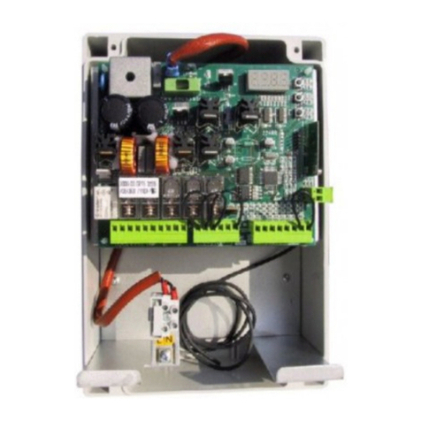
HESA HFA-2000 User manual

Modugno (BA) S.S.
Tel. +39 080 5057 044 Fax +39 080 5057 054
96, km 119.874
•
Via B.Cellini 178
Tel. +39 055 8070 303 Fax +39 055 8070 505
TavarnelleV. P. (FI) •
Roma Via Val Grana 14
Tel. +39 06 8861 415 Fax +39 06 8861 391•
Via Triboniano 25 - 20156 Milano - Italy
Tel.+39 02 38036 1 Fax +39 02 38036 701
•
www.hesa.com e-mail:[email protected]
Operating Instructions
DT01192
Analogue Addressable
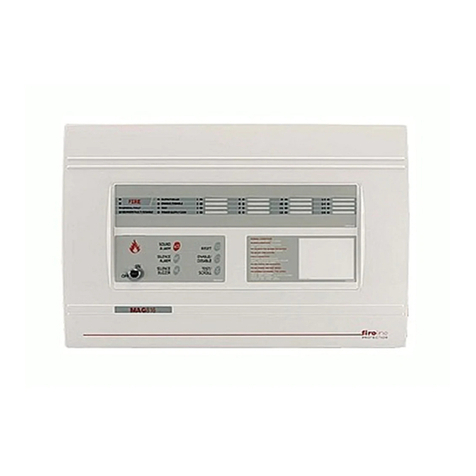
Fire Control Panel
HFA-2000
Software release v 9.6
DRAFT COPY
12/12/2003


i
Table of contents
HFA 2000 Fire Panel ..............................................................................................................................................4
Features found in this release.............................................................................................................................4
Power supply inputs............................................................................................................................................4
Sensors ...............................................................................................................................................................5
Connections to the sensors.............................................................................................................................5
Assigning addresses to the sensors................................................................................................................5
Automatically assigning sensors to zones...................................................................................................5
Manually assigning sensors to zones..........................................................................................................6
Sounding devices................................................................................................................................................6
Connections to the loop powered sounders....................................................................................................6
Assigning addresses to the sounders..............................................................................................................6
Supervision ..................................................................................................................................................6
Automatically programing the sounder addresses.......................................................................................6
Manually assign the sounders .....................................................................................................................6
Buttons.............................................................................................................................................................6
LCD display .....................................................................................................................................................7
Alarm display................................................................................................................................................7
Fault display.................................................................................................................................................8
LEDs................................................................................................................................................................8
Outputs................................................................................................................................................................8
Fixed functions.................................................................................................................................................8
Programmable outputs ....................................................................................................................................8
System Controls..................................................................................................................................................8
Access Codes..................................................................................................................................................8
To enter an access code:.............................................................................................................................8
To silence the sounding devices .....................................................................................................................8
System test......................................................................................................................................................9
To reset the system.........................................................................................................................................9
Entering text characters...................................................................................................................................9
Using menus....................................................................................................................................................9
Turning the system on for the first time...............................................................................................................9
Assign addresses to the sensors...............................................................................................................10
Assign loop powered sounders..................................................................................................................10
Turning the system on after addresses have been assigned ...........................................................................10
If it did not pass the tests, one or more of the following faults could be the cause: ..................................10
Programming the System, access level 3.........................................................................................................10
Programming Menu.......................................................................................................................................11
Event History .................................................................................................................................................11
Time...............................................................................................................................................................12
Date ...............................................................................................................................................................12
Delays............................................................................................................................................................12
Walk Test.......................................................................................................................................................12
To walk test one zone in a loop, for example, zone 7 in loop 2:................................................................13
To walk test all zones in a loop, for example, all zones in loop 1:.............................................................13
To walk test the entire system, all zones in both loops:.............................................................................13
Sensor Addressing ........................................................................................................................................13
Auto-Address .............................................................................................................................................13
Manual-Address.........................................................................................................................................14
If the sensor is on a t-tap........................................................................................................................15
Locate.........................................................................................................................................................15
LED Flashing sequence .........................................................................................................................15
Sounder Addressing......................................................................................................................................15
Auto-Address .............................................................................................................................................15
Manual-Address.........................................................................................................................................16
Add sounder...........................................................................................................................................16
Add all.....................................................................................................................................................16
REMOVE sounder..................................................................................................................................16
Remove all..............................................................................................................................................16
Activation Options...................................................................................................................................17
System Label.................................................................................................................................................17
Sensor Label..................................................................................................................................................17
Zone Label.....................................................................................................................................................17

ii
Codes.............................................................................................................................................................18
Language.......................................................................................................................................................18
Sensor Data...................................................................................................................................................18
Schedule........................................................................................................................................................19
CBE Timers ...................................................................................................................................................19
To program the delay and duration times for an output:............................................................................19
CBE Equations ..............................................................................................................................................20
To erase an equation.................................................................................................................................20
Important note about CBE timers...............................................................................................................20
Load Defaults.................................................................................................................................................20
Erase options.................................................................................................................................................21
Baud Rate......................................................................................................................................................21
Print options...................................................................................................................................................21
Print the Event History ...............................................................................................................................22
Select the Event Option..........................................................................................................................22
Option to print the selected type of event that occurred on a specific date: ..........................................23
Print the Programmed Data .......................................................................................................................23
Print the labels ...........................................................................................................................................23
Print the CBE Equations ............................................................................................................................24
Print the Sensor Data.................................................................................................................................24
Print the events as they occur, in real time................................................................................................25
Status Menu, access level 1..............................................................................................................................25
To access the status menu at access level 1................................................................................................25
Display a zone in alarm .................................................................................................................................26
Display a sensor in alarm ..............................................................................................................................26
Display a zone fault .......................................................................................................................................26
Display a sensor fault ....................................................................................................................................26
Display a loop fault ........................................................................................................................................27
Display a system fault....................................................................................................................................27
Display a sounder fault..................................................................................................................................27
Display a disabled zone.................................................................................................................................27
Display a disabled sensor..............................................................................................................................28
Status and Control Menu, access level 2..........................................................................................................28
Enable / Disable Zones..................................................................................................................................28
Enable / Disable Sensors ..............................................................................................................................28
Access via the serial port ..................................................................................................................................29
Interactive mode.........................................................................................................................................29
Data transfer mode ....................................................................................................................................29
Lockout.......................................................................................................................................................29
Appendix A............................................................................................................................................................30
Control-By-Event (CBE) Equations...................................................................................................................30
Overview............................................................................................................................................................30
Definitions ..................................................................................................................................................30
General structure of the equations.............................................................................................................30
Syntax and Symbols used in the equations......................................................................................................31
Directives...........................................................................................................................................................31
Lloop.........................................................................................................................................................31
Eevent type...............................................................................................................................................31
Variables............................................................................................................................................................31
Ssensor.....................................................................................................................................................31
Zzone........................................................................................................................................................31
Ggroup ......................................................................................................................................................32
Pproduct type............................................................................................................................................32
EV power supply fault...............................................................................................................................32
EB break in a loop wire.............................................................................................................................32
EN sensors not programmed....................................................................................................................32
EK communication fault............................................................................................................................32
Logic Operators.................................................................................................................................................32
+Logical OR..............................................................................................................................................33
&logical AND.............................................................................................................................................33
Logic Modifiers..................................................................................................................................................33
!NOT........................................................................................................................................................33
X.....................................................................................................................................................................33
Normal use, logic modifier .........................................................................................................................33

iii
Special use if the timer statement is not included in the equation.............................................................34
Special use if the timer statement is included in the equation...................................................................34
Y.....................................................................................................................................................................34
( ) parentheses........................................................................................................................................34
Timer Control.....................................................................................................................................................35
Ttimer statement.......................................................................................................................................35
Important note about CBE timers..................................................................................................................35
Syntax Summary...............................................................................................................................................35
Summary of the characters used in the equations and the syntax ...............................................................35
Error messages .............................................................................................................................................36
HFA 2000 Fire Panel.........................................................................................................................................37
ACK button ....................................................................................................................................................37
Silence button................................................................................................................................................37
Reset..............................................................................................................................................................37
Message telling the user that access level 1 is required when certain keys are pressed.............................37
Operation of loop powered sounders ............................................................................................................37
The global option is selected for a loop .....................................................................................................37
The "by zone" option is selected for a loop................................................................................................37
Polling stops when voltage becomes too low for the sensors to operate properly........................................38
Real time alarm display .................................................................................................................................38
The display of zone and sensor disablements are coordinated....................................................................38
Constant display of the number of zones in alarm and number of zones with faults....................................38
Alarm verification...........................................................................................................................................38
Key switch functions......................................................................................................................................39
Center.........................................................................................................................................................39
Left .............................................................................................................................................................39
Right...........................................................................................................................................................39
Additional erase function ...............................................................................................................................40
Cold start........................................................................................................................................................40
New display when resetting...........................................................................................................................40
Power supply failure display..........................................................................................................................40
A CBE equation can now turn on all the sounders........................................................................................40
The LEDs turn on in the sensors that are in alarm........................................................................................41
Access level indication was added................................................................................................................41
System Test:..................................................................................................................................................41
Navigation symbols were placed for all menu selections..............................................................................41
Menu Position and request indicators ...........................................................................................................42
Walk test ....................................................................................................................................................42
Time and Date............................................................................................................................................42
Manual addressing of loop powered sounders..........................................................................................42
Codes.........................................................................................................................................................42
CBE timers.................................................................................................................................................42
Delays, Erase, and Print ............................................................................................................................43
The types of sensor faults are now displayed ...............................................................................................43
Option to allow sensor labels to be associated with the hard addresses......................................................43
The labels should be adjusted under the following conditions:..................................................................44
The labels should NOT be adjusted under the following conditions:.........................................................44
_Toc58983606
Text string removed.......................................................................................................................................44
HESA S.p.A - Analogue Addressable Fire Control Panel HFA-2000 - Operating Instructions
DT01192HE1203R02

4
HFA 2000 Fire Panel
Instructions for operating release 9 of the software
Features found in this release
• Number of loops: 2
• Number of sensors per loop: 64 for a total of 128. T-taps are supported.
• Sensors are assigned addresses automatically.
• Zone numbers are assigned automatically. Sensors can then be assigned to other zones manually if
needed.
• Sensors can be located by having their LEDs display the addresses using coded flashes.
• Display: back lighted LCD, 2 lines, 40 characters on each line. It displays details about alarms and faults as
they occur. It is used for displaying the menus when checking the status of the system and when
programming the system.
• LEDs: 6 to indicate the status of the system.
• Controls: 6 control buttons. 12 number / character buttons for alphanumeric entries.
• Certain system functions can be controlled by a key switch.
• 5 outputs on the main circuit board: Alarm (relay), general fault (open collector), and 3 programmable
outputs (1 relay, 2 open collectors).
• Up to 32 additional programmable outputs using 4 relay expander modules, 8 outputs each.
• Control-by-event (CBE) equations are used to define the combinations of events that drive each
programmable output.
• Names, up to 24 characters long, can be programmed for the system, each zone, and each sensor
• Zones and sensors can be individually disabled.
• The real time clock automatically adjusts for daylight savings time.
• A system test can be activated. This causes all smoke and heat sensors to alarm.
• The system can be walk tested without creating an alarm.
• The silence function turns off the sounder, if it is on. It can be used to turn it back on if necessary. New
activations cancel the silence function.
• Event history memory can hold up to 400 events. It is circular. New events eventually overwrite the oldest.
• A serial port is available for printing or gaining access to the system via a personal computer.
• The event history can be displayed on the LCD or printed out via the printer port; events can be printed as
they occur.
• Data programmed into the system can be printed.
• Default values can be loaded.
• Entire sections of the memory can be erased that holds the events and information programmed by the
installer.
• 4 languages can be supported (although English and Italian are the only ones completed at this time).
• Sensors can be read to determine the signal level and the alarm threshold.
• A day night schedule can be established, a different smoke sensor sensitivity for day and night.
• Critical parts of the system are continuously monitored: Power supply, program memory, site-specific data,
and correct operation of the system.
• Loop powered sounders may be connected to each of the loops. They are supervised and can be
programmed to operate globally so they all sound when the internal sounder activates, or by zone so only
the sounder in a zone activates when there is an alarm, fault, or walk test in that zone.
Power supply inputs
A nominally 24 Vdc power supply is connected to the power inputs.
• If a monitored power supply is used, the normally closed monitoring contacts are connected to the fault
monitoring inputs. These contacts open if a power supply fault occurs, such as the loss of AC power. A
delay can be programmed to prevent power supply warnings during brief power outages.
• If a monitored power supply is not used, a jumper must be connected between the fault monitoring inputs.
• As a backup, the system monitors the internal 24 volt supply voltage. If it drops below 19 Vdc, a power
supply fault occurs even if the monitoring contacts remain closed.

5
Sensors
The panel is designed to operate with the ECO2000 family of analog addressable fire detectors manufactured
by System Sensor ®. They are as follows:
ECO2000M Micro module. Contains supervised input for a
contact
ECO2001 Call point
ECO2003 Photoelectric smoke detector
ECO2005 Thermal detector
Connections to the sensors
The sensors are connected sequentially along each loop. The positive wire connects to the +IN/OUT terminal on
each sensor. The negative wire nearest the LOOP DRIVE terminals on the panel connects to the -IN terminal of
the sensor; the
-OUT terminal connects to the -IN terminal on the next sensor along the loop.
T-taps may be connected to the loop. A T-tap is a branch from a node on the loop. A node is the
common connection between two adjacent sensors on the loop. There are some restrictions when using T-taps,
which are listed below:
• There must be one continuous loop from the loop drive terminals to the loop end terminals.
• Multiple loops are not allowed, which would be multiple paths from the loop drive terminals to the loop end
terminals.
• There can only be one T-tap connected to a node. Multiple branches from the same node are not allowed.
• There is no limit to the number of T-taps providing that each T-tap is the only branch on a node.
• A maximum of 32 sensors can be connected on a tap. This limit is in accordance with EN-54.
• Taps cannot have taps. Taps can only be connected to a node on the loop.
• 64 is the maximum number of sensors that can be connected on a loop including those on T-taps.
For small installations where only one loop is used, connect the LOOP DRIVE terminals to the LOOP END terminals
of the unused loop, positive to positive and negative to negative.
Assigning addresses to the sensors
This is done automatically while in the AUTO-ADDRESS mode for sensors. There is no provision for manually
assigning addresses to the sensors. The addresses are numbered in a predictable sequence from the first
sensor on the loop to the last. When a T-tap is found, the addressing sequence proceeds along the tap until it
finds the end. It then resumes the numbering sequence along the loop. The following illustrates the addressing
sequence when T-taps are used:
Automatically assigning sensors to zones
Zone markers are connected to the first sensor in each zone. The zone numbers are then assigned during the
AUTO-ADDRESS mode. Those sensors nearest the LOOP DRIVE terminals and before the first zone marker are
in zone 1. The sensor with the first zone marker is in zone 2. Sensors between that and the next zone marker
are also in zone 2. There can be up to 15 zones on a loop. A switch is used for setting the zone marker on the
ECO2000M and the ECO2001. Other sensors use a 10K resistor connected between the +RA terminal and the -IN
terminal. For further details, refer to the instructions supplied with each sensor.
To comply with EN-54 standards, zone markers that are connected to sensors on a tap are ignored.
This prevents sensors on the same tap from being in different zones.
Fire
Pane
1234
7101112
Loop
drive
Loop
end
5 6
8 9
Loop wiring using
multiple ‘T’ taps

6
Manually assigning sensors to zones
First, the sensor addresses must be assigned automatically. Next the sensors can be manually assigned to
zones. Only the sensors on the main loop can only be reassigned to other zones. To comply with the EN-54
standards sensors on taps cannot be reassigned to other zones because all sensors on a tap must be in the
same zone.
Sounding devices
The panel has an internal sounder. Loop powered sounders can be added to each of the loops. Depending on
the option programmed, they can operate globally so all sounders duplicate the action of the internal sounder,
or individually as events occur in the zone where they are assigned. The loop powered sounders are
supervised so if any fail or are removed, a warning occurs. The loop powered sounders are from the 500 series
of devices by System Sensor ®: EMA24ALR Wall mounted
sounder
DBS24ALW Detector base
sounder
Connections to the loop powered sounders
They are connected across the loop. There are two sets of (+) and (-) terminals on each sounder. Each pair of
terminals is connected together internally. This provides a convenient means to connect them to the loop.
• No more than 7 sounders should be installed between ECO2000 sensors.
• They should be located between sensors, not between the panel and a sensor.
• The maximum number of these sounders on a loop has not been determined yet. It will be a function of
cable resistance and the volume settings on the sounders.
Assigning addresses to the sounders
The address switches on the sounders should be set to the zone number where they are located. There are as
many available sounder addresses as there are zones on a loop, 1 to 15. The addresses of the sounders that
are installed should be programmed into the panel so they can be supervised. They can be assigned
automatically or manually.
Supervision
The panel routinely polls the sounders. It expects a response from all sounder addresses that have been
programmed into the panel. If it does not get a response, it issues a warning. Whether the sounders are
programmed to operate globally or by zone they can be supervised as long as they have different addresses. If
there are 2 or more sounders in a zone, and each has the same address, it will only detect a supervision fault if
all sounders having that address fail to respond. Supervision cannot detect the loss of a single sounder if its
address is not unique.
Automatically programing the sounder addresses
Unlike auto-addressing for sensors, this does not assign the addresses to the sounders; they are assigned by
the settings of the address switches. This process automatically finds the sensors that are connected to the
system and stores those numbers so they can be included in the supervisory polling operation.
Manually assign the sounders
Individual sounders can be manually assigned or removed from the panel's memory. Also, all the sounder
addresses can be assigned to a loop (1 to 15), or all can be removed.
Buttons
Numbers and characters can be entered during some of the programming functions. This is explained later. The
number keys are shared with the characters as follows:
Key Characters Key Characters Key Characters/contr
ol
1 ( . : / 5 JKL 9 WXYZ
2 ABC 6 MNO 0 ) + - !
3 DEF
(space) 7 PQRS * Back (control)
4 GHI 8 TUV # Enter (control)

7
Control buttons:
Control key Function
ACK After an alarm, this key can be pressed while at any access level. This acknowledgment is
entered into the event history memory along with the access level.
LIST After an access code is entered, this key displays the menu available to that access level.
Also, during an alarm display, this key can be used to display the most recent sensor to
alarm.
SYSTEM RESET When pressed while at access level 2, it clears alarms, faults, and any active programmable
outputs.
SYSTEM TEST When pressed while at access level 3, it causes ECO 2003 and 2005 sensors to report an
alarm (the other sensors can be manually activated.
LAMP TEST Turns on all LEDs when pressed
SILENCE on/off If the sounder or the alarm relay is active, pressing this key while at any access level turns it
off. Pressing it again while at any access level turns it on. New alarms or faults cancel the
silence function. The Silence Inhibit timer prevents it from being silenced immediately after
an event turns it on. This delay is a programmable item. If the delay is programmed to 0,
there is no delay.
Key switch:
Switch position Function
NORMAL The system operates normally. Control is via the keypad and control buttons.
SILENCE All sounding devices are silent while in this position. The silence inhibit timer has no effect.
RESET Clears alarms, and faults. This occurs when this position is first entered. After that, the
system continues to operate normally.
TEST This activates the walk test function for the entire system. The walk test mode continues
while the switch is in this position. It is not governed by the walk test timer.
Maintenance switch:
When on, all polling to the sensors stop and voltage is removed from the loops. This allows sensors to be safely
removed or added to the system while keeping the processor powered. This allows the real time clock to keep
time. While the maintenance switch is on, the system fault LED is on as a warning so it will not be forgotten.
The following operations can be done only while the maintenance switch is on:
• The special access code 987654 can be entered to get to access level 3. This would be used if the normal
access code were forgotten. While at access level 3, the access codes can be displayed and
reprogrammed if necessary.
• The default programming values can be loaded and sections of the EEPROM can be erased.
• Programming steps requiring communication to the sensors are not available while the maintenance switch
is on.
When the maintenance switch is turned off, a system reset is initiated then the system returns to normal
operation. This is similar to a normal system reset with the addition that any disabled zones and sensors are
enabled.
LCD display
It has 2 lines, 40 characters on each line. The backlighting turns on when any key is pressed and remains on
for 15 seconds after the last key was pressed. During standby, the system name is displayed on the top line;
the time and date is displayed on the bottom line. If a system name has not been programmed, HESA HFA-
2000 is displayed on the top line.
Alarm display
When there is an alarm, the zone where the first alarm occurred is displayed on the top line. The zone where
the most recent alarm occurred is displayed on the bottom line along with the number of zones currently in
alarm. The LIST button can be used to display the most recent sensor to alarm on the top line temporarily
replacing the display of the first zone to alarm. The display reverts back to normal when BACK (*) is pressed or
15 seconds after the last key press.

8
Fault display
When a fault occurs, it is displayed on the top line if there are no alarms being displayed.
LEDs
LED . Indicates the following:
ALARM When there is an alarm
DISABLED DETECTORS/ZONES If any zones or sensors are disabled
ZONE FAULT Faults in any sensor in a zone or general fault in a loop
SYSTEM FAULT Faults relating to the system, not limited to any particular loop or zone
POWER When the power supply is functioning correctly (see note below)
SILENCE The feature to silence the sounder is active
Note: The power supply monitoring contacts are closed when the power supply is operating normally; they open
when a fault is sensed such as the loss of AC. As a backup, the system monitors the internal 24 volt supply
voltage. When the connection between the monitoring inputs is closed, and the power supply voltage is greater
than +19Vdc, the green power LED is on. When the contacts open, a power fault warning is issued after the
programmed delay time; the green LED turns off, and the system fault LED turns on. If a power supply is not
available with monitoring, the monitoring inputs should be connected together with a jumper.
Outputs
Outputs are provided to connect to other equipment. Some use relays, others use open collectors. They are
described below:
Fixed functions
• Alarm relay: Activated when an alarm occurs.
• General fault, open collector: Normally on, turns off when any fault occurs in the system.
Programmable outputs
A maximum of 35 outputs are available. They are controlled by the control-by-event (CBE) equations:
• The programmable relay that is located on the main circuit board is output 0.
• The 2 programmable outputs that are located on the main circuit board are outputs 1 and 2.
• Up to 32 more outputs can be provided by installing relay expansion modules. Up to 4 modules can be
added. Each has 8 outputs for a total of 32. These are outputs 3 to 34.
System Controls
Access Codes
The default access codes are as follows. They can be changed while at access level 3.
• 1111 for access level 1
• 22222 for access level 2
• 333333 for access level 3
• Additional access code for access level 3, while the maintenance switch is on: 987654
To enter an access code:
• Enter the access code. The top line of the display blanks, and stars (*) appear for each digit entered.
• Press ENTER (#) to confirm.
• If an error is made, press BACK (*) to start over.
• After a valid access code is entered, ACCESS LEVEL n is displayed in the top line (n = 1, 2, or 3)
• If nothing further is done after 15 seconds, the access level is canceled.
To silence the sounding devices
Devices sound when an alarm or fault occurs. The SILENCE key toggles the silence feature. If the silence
feature is active, new faults or alarms turn it off causing the alarm to sound again.
• Enter the access code for level 1 or 2 then press ENTER (#). The access level is displayed on the top line.
• Press the SILENCE key; the Silence LED turns on enabling the silence feature. This can only can happen
after the silence inhibit time has expired, which is a programmable item.
o Access at level 1: Only the sounders are silenced.

9
o Access at level 2: Both the alarm relay is turned off and the sounders are silenced.
• To turn off the silence feature, press the SILENCE key after entering the access code. Certain conditions
apply: o Access at level 1: The silence feature is turned off only if it was enabled at access level 1.
o Access at level 2: The silence feature is turned off unconditionally.
• Another alternative: Move the key switch to the SILENCE position. It is not affected by the silence inhibit
timer.
Note: The loop powered sounders are updated at the start of each polling sequence to the sensors. Because of
this there will be a slight delay between the time an internal sounder is activated or deactivated until the loop
powered sounders react.
System test
This causes all ECO 2003 smoke detectors and ECO 2005 heat sensors to report an alarm. The ECO 2000M
and ECO 2001 can be manually activated.
• Enter the access code for level 3 then press ENTER (#). The access level is displayed on the top line.
• Press the SYSTEM TEST button to start the test. The Alarm LED turns on, the alarm relay is activated, and
the alarm is displayed on the LCD. All alarms are entered into the event history so their activation can be
checked later.
• A walk test is also available so each sensor can be individually tested without activating the alarm relay. It
can be entered via the menu at access levels 2 or 3 or by use of the key switch. This will be explained later.
To reset the system
This clears all alarms and fault indications. If the alarm or fault condition still occurs, the indication will return
after the reset. After the system is reset, any disabled zones and sensors remain disabled. They must be
individually enabled.
• Enter the access code for level 2 then press ENTER (#) .The access level is displayed on the top line.
• Press the SYSTEM RESET button to start the system reset operation.
• Another alternative: Move the key switch to the RESET position. Reset starts when that switch position is
first reached. It has no effect after that.
Entering text characters
Some programming modes require a text entry such as the characters for naming sensors, zones or entering
the control-by-event (CBE) equations. While in one of those modes, a cursor becomes visible. Enter a character
by pressing the number key that contains that character repeatedly until that character is displayed. Wait 2
seconds and the cursor moves right to the next location. Then the next character can be entered. To cancel an
entry, press BACK (*). It erases the previous character. To erase the entire entry, press BACK (*) repeatedly
until all characters have been erased. Then Press BACK (*) until the menu item is displayed again.
As an example, to enter "K", press 5; "5" is displayed. Press 5 again; "J" is displayed. Press 5 again; "K" is
displayed. After 2 seconds, "K" remains in the display and the cursor advances so the next character can be
entered.
Important note: The 3, D, E, F key also includes a space character. To select the space, keep pressing the 3
key until no character is displayed above the cursor. Wait 2 seconds for the cursor to move then resume
entering characters.
When not in a programming mode requiring character entry, only number entries can be made.
Using menus
While a menu is being accessed, the 2 and 8 keys function as up and down arrow keys respectively for scrolling
through a menu. The # key functions as ENTER for confirming a selection from a menu or an entry. The * key
functions as a BACK key for canceling an entry or going back to the previous menu.
Turning the system on for the first time
SYSTEM FAULT may be displayed on the top line if the EEPROM is blank. The System Fault or Zone Fault
LED, and the internal sounder turn on. No addresses have been assigned to the sensors yet and no hard
addresses (serial numbers) for those sensors are stored. The default time and date are displayed on the bottom
line: 00.00 SAT 01-01-00.
The sounder will be on. To turn it off, refer to the section To silence the internal sounder for instructions.

10
Assign addresses to the sensors
Before the system can operate properly, addresses must be assigned to the sensors. This is done automatically
in the AUTO-ADDRESS mode, which is one of the programming modes. Please refer the to the section entitled
Programming the System, access level 3 for instructions.
Assign loop powered sounders
After the sensors have their addresses assigned, the system polls normally. It also polls the sounders so it is
possible that a sounder fault may occur. Sounders may be assigned that are not installed in the system. After
sensor addressing, the sounders should be assigned to make sure that all the installed sounders, and no
others, will be polled.
Turning the system on after addresses have been assigned
The system is initialized by automatically polling the sensors and testing the following:
• It downloads the serial number from each sensor and compares it to the stored number for each sensor.
• It tests the type of each sensor (ECO2000M, ECO2001, etc.) and compares it to the stored type for that
sensor.
• If it passes all tests, it proceeds to routinely poll the sensors to detect alarms and faults as they occur.
If it did not pass the tests, one or more of the following faults could be the cause:
• One or more sensor had been removed:
The Zone Fault LED turns on and the internal sounder sounds.
Polling continues to monitor the remaining sensors.
• One or both of the loop wires is broken between sensors:
The zone fault LED turns on.
LOOP FAULT is displayed on the top line.
It automatically starts driving the loop from both ends. If there is one break between sensors, all
sensors can be reached by driving the loop from both ends. Polling resumes to monitor the sensors.
• There is more than one break in the loop:
The zone fault LEDs turns on.
LOOP FAULT is displayed on the top line.
It automatically starts driving the loop from both ends. Some sensors will not be able to be reached
after it starts driving the loop from both ends. A zone fault and loop fault result. The remaining sensors
are polled.
• There is a short circuit on a loop:
The zone fault LED turns on.
The isolators in the sensors open the circuit to disconnect the short circuit.
The isolators close again except for those sensors surrounding the short circuit.
If the short circuit is between sensors, the loop is driven from both ends. If the short circuit is between
the panel and the first sensor, or between the last sensor and the panel, the loop is only driven from the
end that is not shorted.
Turn on the maintenance switch to remove power from the loops then make the corrections. Then turn the
maintenance switch back off again.
Programming the System, access level 3
To get into the programming mode proceed as follows:
• Enter the code for access level 3, then press ENTER (#). ACCESS LEVEL 3 is displayed on the top line.
• Press LIST. The first item on the programming menu is EVENT HISTORY and is displayed on the top line. If
there are no alarms being displayed, ACCESS LEVEL 3 is displayed on the bottom line.
• Use the up (2) and down (8) arrow keys to display another menu item.
• Press ENTER (#) to the select the programming item.
Note: If no button has been pressed for 3 minutes while in any of the programming modes at this access level, it
exits and returns to normal operation.

11
Programming Menu
The following programming menu is available while at access level 3:
ZONE LABEL Enter a text label to describe the location of zone.
CODES Displays and programs codes for all 3 access levels.
LANGUAGE Displays current language, allows new language to be selected: English,
Italiano, Deutsch, Francais
SENSOR DATA Displays the current alarm signal level and the threshold of the selected
sensor
SCHEDULE Displays and programs the current schedule. The time for night sensitivity to
start and end, and the levels for night/day sensitivity
CBE TIMERS Displays and programs the timers used in the CBE equations
CBE EQUATIONS Displays and programs the control-by-event, CBE, equations
LOAD DEFAULTS Only available when the maintenance switch is on.
ERASE Erases sections of the EEPROM. Only available when the maintenance
switch is on
BAUD RATE Displays and programs the baud rate for the serial port
PRINT Prints the event history starting with the most recent event.
The following describes the programming steps for each menu item:
Event History
This displays the history of the last 400 events that occurred. New events overwrite the oldest. The most recent
event is displayed first.
• While the programming menu displays EVENT HISTORY, press ENTER (#) to display the most recent event.
If there are no events, NONE is displayed. This would only occur when the system is first put into service.
• If there are events, the time and date of the event is displayed on the bottom line; the type of event is
displayed on the top line. Some events have different levels of display. If it is an alarm, the first display is
like the following example: An alarm on loop 1, zone 2, sensor 14: ALARM L1 Z02 SOUTH ENTRANCE HALL
To see which sensor caused the alarm press ENTER (#) again: ALARM L1 S14 MAIN ENTRANCE
Press * to exit the second level display.
• Select another event by using the up (2) or down (8) arrow key. The up arrow key displays the previous
event. If not displaying the most recent alarm, the down arrow key displays the next event. Moving ahead in
time is like moving down a list of events with the most recent at the bottom. That is why the down arrow is
used for moving forward in time, down the list. To go back in time, the up arrow is used for moving up the
list.
• To move through the event history faster, press 5 then the up or down arrow key. It moves 10 events
forward or backward each time this is done. The next time the up or down arrow key is pressed, it moves in
the normal way, by one event.
Note: If less than 400 events have occurred, when moving back in time using the up arrow key, eventually blank
areas of the memory will be found. When that happens, NONE is displayed. When moving forward in time using
the down arrow key, it stops when it reaches the most recent event.
Menu Item Description
EVENT HISTORY Displays the time, day of week, and date the event occurred and a detailed
description of the event.
TIME Displays and sets the time, 24 hour clock: hh.mm: 00.00 to 23.59
DATE Displays and sets the date: dd-mm-yy
DELAYS Set delays: Silence Inhibit, maximum walk test duration, and power failure
warning.
WALK TEST Selects walk test options and turns the walk test feature on and off.
SENSOR ADDRESSING Automatically assigns addresses to the sensors then sensors to zones.
Sensors can be manually assigned to zones if needed. Sensors can be
located by having their LEDs display the addesses using coded flashes.
SOUNDER
ADDRESSING Assigns sounder addressed, automatically or manually. Also global / by zone
selection
SYSTEM LABEL Enter a text label for the name of the system, displayed during standby mode.
SENSOR LABEL Enter a text label to describe the location of a sensor.

12
Time
This is used to set the time using the 24 hour format: hh:mm ranging from 00.00 to 23.59.
• While the programming menu displays TIME, press ENTER (#) to select it.
• The current time, day of week, and date are displayed on the top line.
• Enter the first digit of the hour. TIME followed by this first digit is displayed.
• Enter the second digit of the hour.
• Press ENTER (#). The "." between the hour and the minute is displayed.
• Enter the digits for the minute.
• Press ENTER (#) to confirm the time. It returns to the programming menu where TIME is displayed again.
To cancel the time entry after the first digit is entered, press BACK (*). The time and date is displayed again.
Then to return to the programming menu, press BACK (*) again.
Date
This is used to set the date using the format: dd-mm-yy. The day of the week is set automatically.
• While the programming menu displays DATE, press ENTER (#) to select it.
• The current time, day of week, and date are displayed on the top line.
• Enter the first digit of the day of the month. DATE followed by this first digit is displayed.
• Enter the second digit of the day of the month.
• Press ENTER (#). The "-" between the day of the month and the month is displayed.
• Enter the digits for the month.
• Press ENTER (#). The "-" between the month and year is displayed
• Enter the digits for the year. If too many days for the month had been entered, it will not accept the year.
Press BACK (*) to clear the entry and start over.
• Press ENTER (#) to confirm the date. It returns to the programming menu where DATE is displayed again. If
the year is not a leap year, and if 29 days had been entered for February, ENTER (#) will not be accepted.
Press BACK (*) to clear the entry and start over.
To cancel the date entry after the first digit is entered, press BACK (*). The time and date is displayed again.
Then to return to the programming menu, press BACK (*) again.
Delays
Press ENTER (#) while DELAYS is displayed. The first item on the menu is displayed: SILENCE INHIBIT. Use
the up or down arrow keys to select the delay that is to be displayed and programmed. Select one of the
following to display:
Display Description
SILENCE INHIBIT After an event turns on the sounding devices, this is the time interval while the silence
function is inhibited. Range: 0 to 200 seconds. Default: 0
WALK TEST Walk testing will end after this time. Range 0 to 60 minutes. Default 0. When 0, walk
testing is disabled. This timer only has effect when walk testing is controlled from the
programming menu at access level 3. It has no effect when the key switch is used.
POWER WARNING This is the time after the power supply contacts open, usually due to a loss of AC, until
the power fault warning occurs. Range 0 to 10 minutes. Default: 0
• While the currently programmed delay is displayed, enter the new value.
• Press ENTER (#) to confirm the entry. It returns to the programming menu where DELAYS is displayed
again. Or, press BACK (*) to clear the entry and start over.
• Or, to keep the currently programmed delay time press BACK (*) to return to the programming menu where
DELAYS is displayed.
Walk Test
There are 3 options:
• One zone in a loop can be walk tested.
• All zones in a loop can be walk tested.
• The entire system can be walk tested, all zones in both loops.

13
To walk test one zone in a loop, for example, zone 7 in loop 2:
• Press ENTER (#) while WALK TEST is displayed from the programming menu.
• LOOP is displayed. Enter the loop number where the zone is located: 2
• Press ENTER (#). LOOP 2 ZONE is displayed.
• Enter the zone number, 7, followed by pressing ENTER (#).
• The following is displayed: LOOP 2 ZONE 07 WALK TEST OFF
• To turn on the walk test press ENTER (#). The display changes to: LOOP 2 ZONE 07 WALK TEST ON
• Walk test the zone. When a sensor is activated, only the sounders sound.
• After the walk test time has expired, which was set when it was programmed in DELAYS, it returns to
normal polling.
• To end the walk test before it times out, press the BACK (*) key while LOOP 2 ZONE 07 WALK TEST ON is
displayed. The display then changes to LOOP 2 ZONE 07 WALK TEST OFF.
• To exit and return to the programming menu, press the BACK (*) key while LOOP 2 ZONE 07 WALK TEST
OFF is displayed.
To walk test all zones in a loop, for example, all zones in loop 1:
• Press ENTER (#) while WALK TEST is displayed from the programming menu.
• LOOP is displayed. Enter the loop number where the zone is located: 1
• Press ENTER (#). LOOP 1 ZONE is displayed.
• Instead of a zone number, press 0.
• The following is displayed: LOOP 1 ALL ZONES WALK TEST OFF
• To turn on the walk test press ENTER (#). The display changes to: LOOP 1 ALL ZONES WALK TEST ON
• Walk test all the zones in the loop. When a sensor is activated, only the sounders sound.
• After the walk test time has expired, which was set when it was programmed in DELAYS, it returns to
normal polling.
• To end the walk test before it times out, press the BACK (*) key while LOOP 1 ALL ZONES WALK TEST ON is
displayed. The display then changes to LOOP 1 ALL ZONES WALK TEST OFF.
• To exit and return to the programming menu, press the BACK (*) key while LOOP 1 ALL ZONES WALK TEST
OFF is displayed.
To walk test the entire system, all zones in both loops:
• Press ENTER (#) while WALK TEST is displayed from the programming menu.
• LOOP is displayed. Instead of a loop number, press 0.
• The following is displayed: SYSTEM WALK TEST OFF
• To turn on the walk test press ENTER (#). The display changes to: SYSTEM WALK TEST ON
• Walk test all the zones in both loops. When a sensor is activated, only the sounders sound.
• After the walk test time has expired, which was set when DELAYS were programmed, it returns to normal
polling.
• To end the walk test before it times out, press the BACK (*) key while SYSTEM WALK TEST ON is displayed.
The display then changes to SYSTEM WALK TEST OFF.
• To exit and return to the programming menu, press the BACK (*) key while SYSTEM WALK TEST OFF is
displayed.
Sensor Addressing
When this is selected, the first item on the sensor addressing menu is displayed: AUTO-ADDRESS
The sensor addressing menu is as follows:
AUTO-ADDRESS It finds all the sounder addresses connected to a
loop
MANUAL-ADDRESS Sounder addresses on a loop are manually
assigned
LOCATE The LEDs on the sensors in the specified zone
display their addesses by using coded flashes.
Use the up (2) and down (8) arrow keys to display a menu item.
Auto-Address
This programming step is used to automatically assign addresses to the sensors in each loop and to assign
zone numbers. The sensor nearest the LOOP DRIVE terminals is assigned address 1, the next is 2, etc. When
it finds a T-tap, it continues the numbering sequence along the tap until it finds the end. It then resumes the
sequence along the loop. The sequence continues until all addresses have been assigned. The maximum is 64.

14
When all the sensors have been assigned addresses, it searches for zone markers along the loop then
automatically assigns the sensors to zones. It ignores sensors on taps. This is because the standards require
all sensors on a tap to be in the same zone.
• While the sensor addressing menu displays AUTO-ADDRESS, press ENTER (#) to select it.
• After ENTER (#) is pressed, LOOP is displayed.
• Press 1 or 2 then press ENTER (#) to select the loop.
Auto-addressing proceeds if no breaks were detected in the loop during initialization.
o WORKING is displayed as auto-addressing proceeds.
o When finished without errors, it returns to the programming menu where SENSOR ADDRESSING is
displayed.
If the loop wire has a break, BREAK followed by +and/or - is displayed indicating which wires are
broken.
o The display remains until BACK (*) is pressed. It then returns to the sensor addressing menu.
o Press BACK (*) again; it returns to the standby mode with the time and date displayed on the
bottom line.
o Remove power to the system, or to the loops by turning on the maintenance switch, then correct
the wiring.
o Turn the power on and repeat the auto-addressing process.
If there there is an error in the installation, FAULT n is displayed where n is the fault code. The fault
codes are listed below:
o The fault display remains until BACK (*) is pressed. It then returns to the sensor addressing menu.
o Press BACK (*) again; it returns to the standby mode with the time and date displayed on the
bottom line.
o Remove power to the system, or to the loops by turning on the maintenance switch, then correct
the wiring.
o Turn the power on and repeat the auto-addressing process.
Auto-addressing fault codes:
Fault
code n
Fault description:
1 More than 64 sensors are connected on the loop
2 Too many taps are connected to a node, only 1 tap is allowed
per node
3 A tap is connected on a tap. Taps are not allowed to have taps
4 More than 32 sensors are connected to a tap
Note: If a loop is not used, connect the LOOP DRIVE terminals to the LOOP END terminals of the same
polarity. Then proceed with auto addressing for that loop even though no sensors are connected. The system
determines that no sensors are connected so it will not expect responses from non-existent sensors during
normal operation.
Manual-Address
This is used to reassign sensors to other zones. It can only be done after all the sensor addresses have been
assigned using auto-addressing. Only the sensors on the main loop can be reassigned to other zones. To
comply with the EN-54 standards sensors on taps cannot be reassigned to other zones because all sensors on
a tap must be in the same zone.
• While the sensor addressing menu displays MANUAL-ADDRESS, press ENTER (#) to select it.
• After ENTER (#) is pressed, LOOP is displayed.
• Press 1 or 2 then press ENTER (#) to select the loop. SENSOR is then displayed.
• Enter the sensor number that is to be reassigned to another zone then press ENTER (#)
• The loop number, sensor number, sensor type, and the zone number where it is currently assigned are
displayed:
For example: LOOP 2 SENSOR 34 ECO2003 ZONE 05
• Enter the new zone number for this sensor. The display blanks and the new zone number appears as it is
entered.
• Press ENTER (#) to confirm the entry. LOOP n SENSOR is displayed so another sensor can be reassigned
on that loop.
• If no more sensors are to be reassigned on that loop press * again to return to the sensor addressing menu.

15
IF THE SENSOR IS ON A T-TAP
• After the sensor number is displayed, "TAP" is displayed after the zone number. Using the previous
example:
LOOP 2 SENSOR 34 ECO2003 ZONE 05 TAP
• It then ignores any attempt to enter a new zone number.
• Press BACK (*) to go back to where it asks for a sensor number.
• Enter a sensor that is not on a T-tap then proceed with the zone assignment.
This programming step can be used to determine the type and zone number for a sensor without reassigning it.
After the loop, sensor, type and zone are displayed, press BACK (*) to quit without changing the zone number.
Locate
Using the LED in each sensor, this feature is used to locate the sensors in the specified zone. It is also used to
verify the addresses of those sensors.
• While the sensor addressing menu displays LOCATE, press ENTER (#) to select it.
• After ENTER (#) is pressed, LOOP is displayed.
• Press 1 or 2 then press ENTER (#) to select the loop. ZONE is then displayed.
• Enter the zone number where the sensors are to be located then press ENTER (#).
• After a couple of seconds, WORKING is displayed and the sensors in that zone flash their addresses using
the format described below. The programming timer starts for 255 seconds (4 minutes 15 seconds) to give
the installer extra time before having to restart it. Normally a key press restarts the programming timer for
180 seconds (3 minutes).
• The programming timer can be restarted for 255 seconds by pressing ENTER (#). Pressing any other
button restarts the timer for the normal 180 seconds.
• To locate another zone on that loop, press BACK (*). The loop number is displayed followed by ZONE.
• Enter the new zone number then press ENTER (#). The LEDs may continue to flash in the previous zone
for several seconds until their flash sequence ends. They do not stop until the flash sequence is completed.
• To locate a zone in the other loop, it is necessary to return to the programming menu where SENSOR
ADDRESSING is displayed, then select LOCATE again to start from the beginning by entering the loop and
zone numbers.
• To exit and return to the programming menu, press the BACK (*) key while it requests a new zone. It will
take about 30 seconds before normal polling resumes on that loop.
LED FLASHING SEQUENCE
A short flutter of the LED is used to indicate the first (most significant) digit followed by a 1.5 second pause.
The LED then pulses the number of the address (2 = 2 pulses). A long pulse (1 second) is used to indicate a
zero digit (instead of no pulse). A 1.5 second pause follows the last pulse of the first digit. Two flutters of the
LED are used to indicate the second digit. The second digit follows in the same fashion as the first. The
process is repeated until blink mode is exited.
Sounder Addressing
The sounder addresses are set by the address switches on each sounder to the zone number where they are
installed. This programming step is used to store the sounder addresses so they can be supervised by polling
them. Sounders can be automatically or manually assigned. They can also be set to operate globally or by
zone. When sounder addressing is selected, the first item on the sounder addressing menu is displayed: AUTO-
ADDRESS.
The sounder addressing menu is as follows:
AUTO-ADDRESS It finds all the sounder addresses connected to a loop
MANUAL-ADDRESS Sounder addresses on a loop are manually assigned
ACTIVATION OPTIONS Selects between global activation or activation by
zone
Use the up (2) and down (8) arrow keys to display a menu item.
Auto-Address
• While the sensor addressing menu displays AUTO-ADDRESS, press ENTER (#) to select it.
• After ENTER (#) is pressed, LOOP is displayed.
• Press 1 or 2 then press ENTER (#) to select the loop.
• WORKING is displayed as auto-addressing proceeds.
• When finished, it returns to the sounder addressing menu where AUTO-ADDRESS is displayed.

16
• Press BACK (*) to return to the programming menu where SOUNDER ADDRESSING is displayed.
Manual-Address
• While the sounder addressing menu displays MANUAL-ADDRESS, press ENTER (#) to select it.
• After ENTER (#) is pressed, LOOP is displayed.
• Press 1 or 2 then press ENTER (#) to select the loop.
• The list of all sounders currently assigned to that loop is displayed. For example, if all are assigned:
1 2 3 4 5 6 7 8 9 10 11 12 13 14 15
If no sounders are assigned, NONE is displayed.
• Press ENTER (#) while the list is displayed to proceed to the menu for manual addressing or BACK (*) to
exit.
• The first item on the manual addressing menu is displayed: SAVE
Normally, after displaying the currently programmed list of sounders, SAVE would not be used. Use the up
(2) and down (8) arrow keys to display another menu item.
The manual addressing menu is as follows:
SAVE Saves the displayed list of sounders
ADD SOUNDER The sounder number entered is added to the list
ADD ALL Assigns all 15 sounders to the loop
REMOVE SOUNDER The sounder number entered is removed from
the list
REMOVE ALL Deletes all sounders from the loop
ADD SOUNDER
• While the manual addressing menu displays ADD SOUNDER, press ENTER (#) to select it. The display
blanks.
• Enter a sounder address that is to be added to the list of sounders.
• Press ENTER (#) to confirm the entry. The display blanks again.
• Continue to add sounder addresses in any order. Follow each entry by pressing ENTER (#).
• When finished adding sounder addresses, press BACK (*)
• The revised list of sounders is displayed.
• If more sounders are to be added, press ENTER (#) and select ADD SOUNDER again then enter those
sounders.
• When the list of sounders in the display is correct, press ENTER (#), or press BACK (*) to quit without
saving the changes.
• After ENTER (#) is pressed, the menu item SAVE is then displayed. Press ENTER (#) again to save the
revised list.
• It then returns to the sounder addressing menu where MANUAL-ADDRESS is displayed.
Important note! To save the list be sure to press ENTER (#) to display SAVE then press ENTER (#) again to
complete the saving process.
ADD ALL
This adds all available sounder addresses to the list, 1 to 15.
• While the manual addressing menu displays ADD ALL, press ENTER (#) to select it.
• The list of all sounders is displayed: 1 to 15.
• To save the list, press ENTER (#), or press BACK (*) to quit without saving the changes.
• After ENTER (#) is pressed, the menu item SAVE is then displayed. Press ENTER (#) again to save the
revised list.
• It then returns to the sounder addressing menu where MANUAL-ADDRESS is displayed.
Note: This can be used if most sensor addresses are installed. All sensors addresses can be added to the list
then the few that are not used can be removed (explained next).
REMOVE SOUNDER
This process is identical to that for adding individual sounders except the sounder addresses that are entered
are removed from the list.
REMOVE ALL

17
This process is identical to that for adding all sounder addresses except all the sounder addresses are removed
from the list. After ENTER (#) is pressed while REMOVE ALL is displayed, NONE is displayed. Indicating that
there are no sounders on the list. Be sure to use the save operation next.
ACTIVATION OPTIONS
There are 2 choices for each loop:
GLOBAL All loop powered sounders follow the action of the internal
sounder.
BY ZONE An alarm, fault, or walk test in a zone will cause only the loop
powered sounder in that zone to sound.
In both cases, the sounder addresses should be set to the zone where they are installed then their addresses
should be programmed using one of the addressing procedures. This allows the sounders to be supervised. To
select the option:
• While the sounder addressing menu displays ACTIVATION OPTIONS, press ENTER (#) to select it.
• After ENTER (#) is pressed, LOOP is displayed.
• Press 1 or 2 then press ENTER (#) to select the loop.
• The option currently programmed is displayed.
• Use the up (2) and down (8) arrow keys to toggle between GLOBAL and BY ZONE.
• Press ENTER (#) to select the item. It also saves it.
• It then returns to the sounder addressing menu where ACTIVATION OPTIONS is displayed.
System Label
This label describes the installation. It can be anything. For example, it can be the name of the building, or the
business. During the standby mode, the system label is displayed on the top line. The time and date is
displayed on the bottom line. If no system label had been programmed, HESA 2000 is displayed instead.
When entering this programming mode, the currently programmed label, if any, is displayed on the top
line. To keep this label, press BACK (*) and it returns to the programming menu. To change it, refer to the
section at the beginning of this document entitled Entering text characters then proceed as follows:
• While the programming menu displays SYSTEM LABEL, press ENTER (#).
• The current label, if any, is displayed on the top line.
• Enter each character. Up to 24 characters may be entered. Press BACK (*) as many times as necessary to
cancel one or more characters, or the entire entry.
• Press ENTER (#) to confirm the new label. It returns to the programming menu.
Sensor Label
This label describes the location of the sensor. When entering this programming mode, the currently
programmed label, if any, is displayed on the top line. To keep this label, press BACK (*) and it returns to the
programming menu. To change it, refer to the section at the beginning of this document entitled Entering text
characters then proceed as follows:
• While the programming menu displays SENSOR LABEL, press ENTER (#). LOOP is displayed.
• Enter the loop number, 1 or 2, where the sensor is located then press ENTER (#). SENSOR is displayed.
• Enter the sensor number, 1 to 64, then press ENTER (#).
• The current label, if any, is displayed on the top line.
• Enter each character. Up to 24 characters may be entered. Press BACK (*) as many times as necessary to
cancel one or more characters, or the entire entry.
• Press ENTER (#) to confirm the new label. It returns to the programming menu.
Zone Label
This label describes the location of zone. When entering this programming mode, the currently programmed
label, if any, is displayed on the top line. To keep this label, press BACK (*) and it returns to the programming
menu. To change it, refer to the section at the beginning of this document entitled Entering text characters then
proceed as follows:
• While the programming menu displays ZONE LABEL, press ENTER (#). LOOP is displayed.
• Enter the loop number, 1 or 2, where the zone is located then press ENTER (#). ZONE is displayed.
• Enter the zone number, 1 to 15, then press ENTER (#).
• The current label, if any, is displayed on the top line.

18
• Enter each character. Up to 24 characters may be entered. Press BACK (*) as many times as necessary to
cancel one or more characters, or the entire entry.
• Press ENTER (#) to confirm the new label. It returns to the programming menu.
Codes
When selected from the programming menu, the following is displayed: ACCESS LEVEL.
• Enter the access level to display: 1, 2, or 3 followed by pressing ENTER (#).
• The access code currently programmed for that access level is displayed.
• To change the code, enter the new number. It replaces the previous number in the display. Access level 1
uses 4 digits, access level 2 uses 5 digits, and access level 3 uses 6 digits.
• If correct, press ENTER (#). If incorrect, press BACK (*) to start over.
• To exit and return to the programming menu, press BACK (*) while ACCESS LEVEL is displayed.
Language
When selected from the programming menu, the currently programmed language is displayed. The following is
a list of the available languages: English, Italiano, Deutsch, and Francais. (only English and Italian are
complete at this time).
• To change, use the up and down arrow keys to select another language.
• Press ENTER (#) to confirm the entry and save it.
• Or, press BACK (*) to exit and return to the programming menu.
Sensor Data
When selected from the programming menu:
• It prompts for a loop number. Enter 1 or 2 followed by ENTER (#).
• It then prompts for a sensor number. Enter a number from 1 to 64. If a number is entered that is not
installed, it exits and returns to the programming menu where SENSOR DATA is displayed again.
• It displays the current signal level and the threshold (limit). The following is a typical display for an
ECO2003 smoke detector: LOOP 2 SENSOR 12 SIGNAL/LIMIT 034/133. The value 034 is the current
signal level; 133 is the limit. When it reaches the limit, it reports an alarm.
Note: When a signal level or threshold (limit) is retrieved from a sensor, the value can range from 0 to 255. This
represents a pulse width that is 15 times that value in microseconds. Therefore, the pulse width range can be
between 0 and 3825 microseconds. Sensor limits and signal levels are generally specified in microseconds.
The limits specified for the ECO2003 smoke detector have an approved range of 1600 to 3000 microseconds.
This corresponds to values between 107 and 200 that is displayed in SENSOR DATA. To simplify setting the
sensitivity, this range is divided into 9 different values. These values are used when setting the day/night
schedule for the ECO2003 smoke detectors. The 3 types of data are listed in the table below:
Sensitivit
y
Setting
Value used
by sensor Pulse width
Microsecon
ds
1 200 3000
2 189 2835
3 178 2670
4 167 2505
5 155 2325
6 144 2160
7 ** 133 ** 1995 **
8 120 1800
9 107 1605
** Factory default values for the ECO2003
Table of contents
