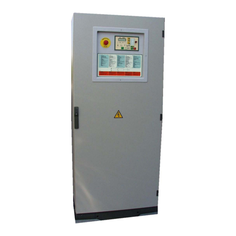
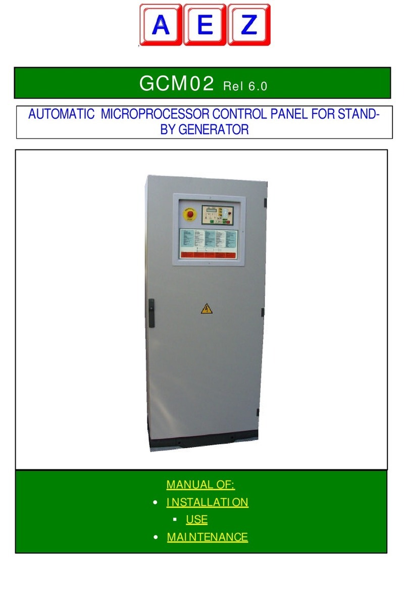
AEZ GCM02 User manual

GCM02-UT-CEE-04 OWNER’S MANUAL
GCM
GCMGCM
GCM-
--
-02
0202
02
Quadro automatico a microprocessore per gruppo elettrogeno d’emergenza
Automatic microprocessor control panel for stand-by generator
Armoire automatique a microprocesseur pour groupe électrogène de secours
Cuadro automático con microprocesador para grupo electrógeno de emergencia
automatische Mikroprozessorsteuerung für Notstromaggregat
Quadro automático com microprocessador para grupo electrógeno de emergência
Automatisch bedieningspaneel (met microprocessor) voor noodstroomaggregaat
Automatisk mikrostyret styretavle for reservegenerator
Automaattinen mikroprosessorilla varustettu taulu hätätilageneraattorilaitteistolle
Automatisk el skap med mikroprosessor for nødgenerator
Automatisk kontrollpanel med mikroprocessor för nödströmsaggregat
ΑΥΤΟΜΑΤΟΣ ΠΙΝΑΚΑΣ ΜΕ ΜΙΚΡΟΕΠΕΞΕΡΓΑΣΤΗ ΓΙΑ ΗΛΕΚΤΡΙΚΗ ΓΕΝΝΗΤΡΙΑ ΕΠΕΙΓΟΥΣΑ ΑΝΑΓΚΗΣ

GCM02-UT-CEE-04 2/98
INDICE
MANUALE DELL’UTENTE..................................................................................................................................................5
1. SCOPO ..........................................................................................................................................................................5
2. PRINCIPIO DI FUNZIONAMENTO ................................................................................................................................5
3. VISTA DEL MODULO GC-M02....................................................................................................................................6
4. DESCRIZIONE FUNZIONALE DEI COMPONENTI DEL PANNELLO...........................................................................7
5. COMANDI E FUNZIONAMENTO....................................................................................................................................9
6. PROGRAMMAZIONE....................................................................................................................................................10
7. COMANDI VARI...........................................................................................................................................................10
8. FUNZIONI SPECIALI ....................................................................................................................................................11
9. PICCOLA MANUTENZIONE.......................................................................................................................................11
INDEX
USER MANUAL ................................................................................................................................................................13
1. PURPOSE.....................................................................................................................................................................13
2. OPERATING PRINCIPLE ...........................................................................................................................................13
3. VIEW OF THE GC-M02 UNIT3. VIEW OF THE GC-M02 UNIT....................................................................................14
4. FUNCTIONAL DESCRIPTION OF THE PANEL COMPONENTS ................................................................................15
5. COMMANDS AND OPERATING ..................................................................................................................................17
6. PROGRAMMING...........................................................................................................................................................18
7. VARIOUS COMMAND ..................................................................................................................................................18
8. SPECIAL FUNCTIONS .................................................................................................................................................19
9. SIMPLE MAINTENANCE ..............................................................................................................................................19
INDEX
MANUEL DE L’UTILISATEUR ..........................................................................................................................................21
1. BUT ..............................................................................................................................................................................21
2. PRINCIPE DE MARCHE..............................................................................................................................................21
3. VISUALISATION DU MODULE GC-M02 ....................................................................................................................22
4. DESCRIPTIONS DES DIFFERENTS COMPOSANTS ................................................................................................23
5. COMMANDE ET FONCTION.......................................................................................................................................25
6. PROGRAMMATION......................................................................................................................................................26
7. COMMANDES...............................................................................................................................................................26
8. FONCTIONS SPECIALES ............................................................................................................................................27
9. ENTRETIEN SIMPLE..................................................................................................................................................27
ÍNDICE
MANUAL PARA EL USUARIO..........................................................................................................................................29
1. FINALIDAD....................................................................................................................................................................29
2. PRINCIPIO DE FUNCIONAMIENTO ............................................................................................................................29
3. VISTA DEL MÓDULO GCM-02.....................................................................................................................................30
4. DESCRIPCIÓN DEL FUNCIONAMIENTO DE LOS COMPONENTES DEL CUADRO ................................................31
5. MANDOS Y FUNCIONAMIENTO..................................................................................................................................33
6. PROGRAMACIÓN.........................................................................................................................................................34
7. OTROS MANDOS.........................................................................................................................................................34
8. FUNCIONES ESPECIALES..........................................................................................................................................34
9. MANTENIMIENTO MENOR..........................................................................................................................................35

GCM02-UT-CEE-04 3/98
INHALTSVERZEICHNIS
BENUTZERHANDBUCH...................................................................................................................................................36
1. ZWECK ........................................................................................................................................................................36
2. FUNKTIONSWEISE.....................................................................................................................................................36
3. ANSICHT DES MODULS GC-M02 ...............................................................................................................................37
4. FUNKTIONSBESCHREIBUNG DER GERÄTE AUF DER BEDIENTAFEL..................................................................38
5. BEFEHLE UND FUNKTIONEN.....................................................................................................................................40
6. PROGRAMMIERUNG...................................................................................................................................................41
7. VERSCHIEDENE BEFEHLE.........................................................................................................................................41
8. SONDERFUNKTIONEN................................................................................................................................................41
9. KLEINE WARTUNGSARBEITEN................................................................................................................................42
ÍNDICE
MANUAL DO UTILIZADOR...............................................................................................................................................43
1. FINALIDADES..............................................................................................................................................................43
2. PRINCÍPIO DE FUNCIONAMENTO ............................................................................................................................43
3. VISTA DO MÓDULO GC-M02 ...................................................................................................................................44
4. DESCRIÇÃO FUNCIONAL DOS COMPONENTES DO PAINEL.................................................................................45
5. COMANDOS E FUNCIONAMENTO .............................................................................................................................47
6. PROGRAMAÇÃO..........................................................................................................................................................48
7. COMANDOS VÁRIOS..................................................................................................................................................48
8. FUNÇÕES ESPECIAIS.................................................................................................................................................48
9. PEQUENA MANUTENÇÃO ........................................................................................................................................49
INHOUD
HANDLEIDING VOOR DE GEBRUIKER ..........................................................................................................................50
1. DOEL............................................................................................................................................................................50
2. WERKING VAN HET ELEKTRISCH AGGREGAAT.....................................................................................................50
3. OVERZICHT VAN DE EENHEID GC-M02...................................................................................................................52
4. OMSCHRIJVING VAN DE ONDERDELEN VAN HET PANEEL..................................................................................53
5. BEDIENING EN WERKING...........................................................................................................................................55
6. PROGRAMMERING......................................................................................................................................................56
7. DIVERSE COMMANDO’S.............................................................................................................................................57
8. SPECIALE FUNCTIES..................................................................................................................................................57
9. KLEIN ONDERHOUD..................................................................................................................................................57
INDHOLDSFORTEGNELSE
BRUGERMANUAL ............................................................................................................................................................59
1. FORMÅL ......................................................................................................................................................................59
2. FUNKTIONSPRINCIP ..................................................................................................................................................59
3. SKEMA OVER GC-M02 MODULET..............................................................................................................................60
4. BESKRIVELSE AF KOMPONENTERNES FUNKTIONER PÅ STYRETAVLEN..........................................................61
5. BETJENINGSKNAPPER OG FUNKTION.....................................................................................................................63
6. PROGRAMMERING......................................................................................................................................................64
7. FORSKELLIGE BETJENINGER ...................................................................................................................................65
8. SPECIELLE FUNKTIONER...........................................................................................................................................65
9. MINDRE VEDLIGEHOLDELSE...................................................................................................................................65

GCM02-UT-CEE-04 4/98
SISÄLTÖ
KÄYTTÄJÄLLE TARKOITETTU KÄYTTÖOPAS...............................................................................................................67
1. TARKOITUS.................................................................................................................................................................67
2. TOIMINTAPERIAATE...................................................................................................................................................67
3. YKSIKÖN GC-M02 KUVA.............................................................................................................................................68
4. TAULUN KOMPONENTTIEN TOIMINNALLINEN KUVAUS........................................................................................69
5. HALLINTALAITTEET JA TOIMINTA .............................................................................................................................71
6. OHJELMOINTI ..............................................................................................................................................................72
7. ERI HALLINTALAITTEET..............................................................................................................................................73
8. ERITYISTOIMINNOT ....................................................................................................................................................73
9. PIENET HUOLTOTOMENPITEET..............................................................................................................................73
INNHOLDSFORTEGNELSE
BRUKERMANUAL.............................................................................................................................................................75
1. HENSIKT......................................................................................................................................................................75
2. FUNKSJONSMÅTE......................................................................................................................................................75
3. ILLUSTRASJON AV MODUL GC-M02 .........................................................................................................................76
4. FUNKSJONSBESKRIVELSE AV EL-SKAPETS KOMPONENTER .............................................................................77
5. KOMMANDOER OG FUNKSJON.................................................................................................................................79
6. PROGRAMMERING.........................................................................................................................................................80
7. DIVERSE KOMMANDOER ...............................................................................................................................................81
8. SPESIALFUNKSJONER ...................................................................................................................................................81
9. ORDINÆRT VEDLIKEHOLD ...........................................................................................................................................81
INNEHÅLLSFÖRTECKNING
BRUKSANVISNING FÖR ANVÄNDAREN........................................................................................................................83
1. ÄNDAMÅL....................................................................................................................................................................83
2. HUVUDFUNKTION ......................................................................................................................................................83
3. ÖVERSYN AV MODUL GC-M02.................................................................................................................................84
4. FUNKTIONSBESKRIVNING AV PANELENS KOMPONENTER .................................................................................85
5. KONTROLLER OCH FUNKTION..................................................................................................................................87
6. PROGRAMMERING......................................................................................................................................................88
7. OLIKA KONTROLLER...................................................................................................................................................89
8. SPECIAL FUNKTIONER...............................................................................................................................................89
9. MINDRE UNDERHÅLL................................................................................................................................................89
ΠΕΡΙΕΧΟΜΕΝΑ
ΕΓΧΕΙΡΙ∆ΙΟ ΤΟΥ ΧΡΗΣΤΗ ...............................................................................................................................................91
1. ΣΚΟΠΟΣ ......................................................................................................................................................................91
2. ΠΩΣ ΛΕΙΤΟΥΡΓΕΙ ΜΙΑ ΗΛΕΚΤΡΙΚΗ ΓΕΝΝΗΤΡΙΑ ΕΠΕΙΓΟΥΣΑΣ ΑΝΑΓΚΗΣ...............................................................91
3. ΑΠΟΨΗ ΤΟΥ ΑΡΘΡΩΜΑΤΟΣ GC-M02 .......................................................................................................................92
4. ΛΕΙΤΟΥΡΓΙΚΗ ΠΕΡΙΓΡΑΦΗ ΤΩΝ ΕΞΑΡΤΗΜΑΤΩΝ ΤΟΥ ΠΑΝΕΛ ..............................................................................93
5. ΕΝΤΟΛΕΣ ΚΑΙ ΛΕΙΤΟΥΡΓΙΑ.........................................................................................................................................95
6. ΠΡΟΓΡΑΜΜΑΤΙΣΜΟΣ ..................................................................................................................................................96
7. ∆ΙΑΦΟΡΕΣ ΕΝΤΟΛΕΣ ..................................................................................................................................................97
8. ΕΙ∆ΙΚΕΣ ΛΕΙΤΟΥΡΓΙΕΣ.................................................................................................................................................97
9. ΜΙΚΡΗ ΣΥΝΤΗΡΗΣΗ ..................................................................................................................................................97

FILE VER DATA ULT. VERSIONE PAGINA
GCM02-UT-CEE-04 AS/01 28/09/2001 pag. 5 di 98
G
CR CG
M02
M
Fig. 1
UTILIZZO
QGE
R
MANUALE DELL’UTENTE
GENERALITÀ
Complimenti per aver scelto la scheda GC-M02 per la gestione del Vostro gruppo elettrogeno.
Di seguito apprezzerete le notevoli prestazioni e la molteplicità di applicazioni consentite dall'alta tecnologia che contiene.
Si tratta di un modulo elettronico a microprocessore che, oltre alla gestione totale del gruppo elettrogeno e della commutazione, è
predisposto per la comunicazione seriale diretta con un PC oppure tramite un GSM: sarà possibile gestire e controllare totalmente il
Vostro gruppo elettrogeno da chilometri di distanza.
La GC-M02 è dotata di una completa strumentazione digitale che consente di monitorare tutti i parametri della rete, del generatore e
del motore.
Il MANUALE DELL'UTENTE ha lo scopo di fornire una guida chiara e semplice, al fine di consentire un uso rapido, completo e
sicuro del gruppo elettrogeno.
1. SCOPO
In questo manuale vengono fornite tutte le informazioni necessarie per:
1. conoscere il principio di funzionamento del gruppo;
2. interpretare le indicazioni del pannello elettronico;
3. governare la scheda elettronica nelle varie esigenze di servizio;
4. effettuare i controlli minimi necessari a garantire l'efficienza del proprio gruppo.
Non sono trattati elementi tecnici o di regolazione poiché gestiti dall'installatore con la messa in servizio dell'impianto.
2. PRINCIPIO DI FUNZIONAMENTO
COME FUNZIONA UN GRUPPO ELETTROGENO DI EMERGENZA
Nella fig. 1sono rappresentati i componenti dell'impianto, composti da una rete pubblica R, un gruppo elettrogeno GM, un quadro di
comando e controllo QGE, con all'interno un contattore rete CR, un contattore gruppo CG, ed il modulo di comando e controllo M02.
R Rete pubblica QGE Quadro di comando e controllo CR Contattore rete
GM Gruppo elettrogeno
(generatore+motore)
M02 Scheda elettronica di comando e controllo CG Contattore gruppo
Ipotizziamo di essere nella condizione in cui la rete R è nei valori normali, il contattore rete CR è chiuso, e l'utilizzo è alimentato
dalla rete.
La M02 sorveglia la rete R ed in caso di un’anomalia o per l’abbassamento o la mancanza di una fase o per dissimmetria delle fasi
stesse, agisce come segue:
comanda l'apertura del contattore rete CR;
comanda l'avviamento del gruppo G-M, e raggiunte le condizioni di funzionamento stabilite, comanda la chiusura del contattore CG
e va ad alimentare l’utilizzo tramite il generatore G;
N.B.: Durante il funzionamento il motore M ed il generatore G vengono sono sorvegliati da eventuali anomalie che determinerebbero
l'arresto immediato del gruppo, la memorizzazione e la visualizzazione sul display della causa dell’allarme (es. bassa pressione olio,
sovraccarico, ecc).

FILE VER DATA ULT. VERSIONE PAGINA
GCM02-UT-CEE-04 AS/01 28/09/2001 pag. 6 di 98
al ritorno della rete R nei valori normali, la M02, dopo un ritardo stabilito, apre il contattore gruppo CG e, dopo un secondo, chiude il
contattore CR alimentando in questo modo l'utilizzo con la rete R;
il gruppo continua a funzionare per almeno un minuto per smaltire il calore eccessivo ed alla fine del tempo di raffreddamento si
arresta automaticamente.
N.B.: A gruppo fermo sono attive le protezioni del livello carburante, livello acqua e sovraccarico della commutazione rete/gruppo
(CR/CG) ed un’eventuale anomalia determinerebbe lo stato di allarme con segnalazione acustica.
N.B.: Sul display della M02 viene visualizzato lo stato del funzionamento del GM per facilitare l’utente nella gestione dello stesso.
Per garantire la perfetta efficienza del gruppo un carica batteria automatico mantiene la batteria perfettamente carica, un sistema di
rabbocco automatico del carburante mantiene giornalmente costante il livello nel serbatoio, ed un sistema di preriscaldo mantiene il
motore pronto all’intervento.
3. VISTA DEL MODULO GC-M02
Descrizione funzionale dei blocchi del pannello.
1. Display alfanumerico di visualizzazione di tutte le misure e
della descrizione letterale del tipo di allarme (es. RISERVA
CARBURANTE)
3. Pulsanti +/- di selezione misure e
pulsante di reset per ripristino funzioni o
sblocco allarme.
2. Commutatore di programmazione:
1 Prova automatica. (T)
2 Funzionamento automatico. (A)
3 Blocco (Locked) logica esclusa.
4 Alimentazione forzata da rete (CR)
5 Abilitazione avviamento manuale.
6 Alimentazione forzata da generatore (CG).
4. Stato della rete e della
commutazione rete gruppo
5. Comando manuale della
pompa carburante
6. Intervento della protezione
differenziale
10. Il lampeggio indica che il
microprocessore sta elaborando una
funzione.
9. Pulsanti per il comando manuale di
marcia o arresto
8. Segnalazioni di gruppo in moto e di
allarme motore
7. Carica batteria e
batteria alimentati

FILE VER DATA ULT. VERSIONE PAGINA
GCM02-UT-CEE-04 AS/01 28/09/2001 pag. 7 di 98
1
2
3
4
5
6
RETE V12 389
HZ 50.0
RETE V12 V23 V13
389 388 394
RETE V1N V2N V3N
224 221 224
GEN. V12 389
HZ 50.1 I1 32
GEN. V12 V23 V13
389 388 392
GEN. V1N V2N V3N
222 221 221
GEN. I1 32
I2 0 I3 0
4. DESCRIZIONE FUNZIONALE DEI COMPONENTI DEL PANNELLO
DESCRIZIONE DEI COMPONENTI
Commutatore di programmazione per la selezione del tipo
di funzionamento:
1. Prova automatica (AUTOMATIC TEST)
2. Funzionamento automatico standard (AUTOMATIC RUNNING)
3. Condizione di blocco (LOCKED ENGINE) elettronica disattivata, idonea per le fasi
di manutenzione.
4. Alimentazione forzata dell’utilizzo tramite la rete (MANUAL MAINS).
5. Abilita il pulsante di start per l’avviamento manuale (MANUAL START).
6. Alimentazione forzata dell’utilizzo tramite il generatore (MANUAL GEN. SET).
Pulsanti di selezione lettura sul display: consentono di selezionare la pagina di lettura necessaria e di
programmare l’orologio settimanale.
Pulsante di RESET/ENTER: ripristino delle funzioni ed eliminazione di stati di allarme (RESET), o conferma i
dati durante la programmazione (ENTER).
Premere una volta per escludere l’allarme acustico (SILENT), due volte per resettare.
DESCRIZIONE DELLE VARIE PAGINE DI MISURE
Quando la rete è presente vengono visualizzate la tensione e la frequenza di rete.
Per un controllo più dettagliato della rete, sono visualizzate le tre tensioni concatenate fra
fase e fase...
Indica le tre tensioni stellate fra fase e neutro della rete.
Quando è in funzione il gruppo la misura passa automaticamente su queste misure che
visualizzano la tensione del generatore, la frequenza e la corrente sulla fase 1.
Per un controllo più dettagliato del generatore, sono visualizzate le tre tensioni concatenate
fra fase e fase.
Indica le tre tensioni stellate fra fase e neutro del generatore.
Le tre correnti di fase consentono di verificare lo stato del carico sulla singola fase del
generatore.

FILE VER DATA ULT. VERSIONE PAGINA
GCM02-UT-CEE-04 AS/01 28/09/2001 pag. 8 di 98
Le potenze indicano lo stato ed il tipo di carico sul generatore:
KVA = kilovoltampere = potenza apparente; KW = kilowatt = potenza reale; KVAr = kilovar
= potenza reattiva.
Cosfì = fattore di potenza = angolo di sfasamento fra tensione e corrente, con il carico
normale indica L – 0.xx, mentre se capacitivo indica C + 0.xx.
(ATTENZIONE! In quest’ultimo caso significa che è inserito il rifasamento automatico
dell’impianto, che durante il funzionamento del generatore DEVE essere assolutamente
disinserito: CONDIZIONE PERICOLOSA)
Sono riportate la tensione della batteria e la corrente di carica in caso di rete presente,
gruppo fermo e di corrente inferiore a 2 A. La tensione non deve superare i 13,5 V in caso di
batterie da 12Vdc ed i 27V per le batterie da 24Vdc; quando il gruppo è in moto le tensioni
sono superiori poiché condizionate dal generatore carica batteria.
RPM: giri motore. LC: percentuale del carburante nel serbatoio.
PO: pressione olio. TM: temperatura motore.
Attenzione! LC, PO, TM sono visualizzate solo se sono collegate le rispettive sonde.
Conta ore totalizzatore: il valore rimane memorizzato anche se si scollega la batteria.
Stato degli ingressi: viene utilizzata dagli installatori in fase di messa a punto dell’impianto.
Indica lo stato delle uscite viene utilizzata dagli installatori in fase di messa a punto
dell’impianto.
Orologio settimanale: si azzera ogni volta che si interrompe la batteria, e serve per il
funzionamento della prova automatica, del blocco automatico e dei gruppi di riserva (vedere
programmazione).
Protezione differenziale: l’intervento è indicato dalla segnalazione TRIP, ed interviene
quando la corrente di dispersione verso terra supera i valori impostati (indicati fra parentesi).
Il blocco indica che l’impianto alimenta l’utilizzo.
Il traliccio rappresenta la rete pubblica ed il led acceso indica che le tre fasi
sono nei parametri stabiliti, mentre quando è spento indica il contrario. I led
CG e CR indicano quale contattore è chiuso per alimentare l’utilizzo. Il led
TRIP fisso indica l’intervento della protezione differenziale, se lampeggiante
significa che vi è una dispersione superiore al 50% sul valore previsto. Il led sul generatore indica che il
gruppo è in moto.
Il led sul motore indica stato di allarme del gruppo.
Carica batteria e batteria.
I led indicano carica batteria alimentato e alimentazione del modulo M02 da parte della batteria.
GEN. 0KVAr
7KVA 7KW
GEN. COS. L-1.00
FREQ 50.0HZ
DIFFER 0,00 ( 0,03 )
A
RITARDO ( 0,06) S
IN 123456789ABCD
00111111111101
OUT 123456789ABC
01010000
LUN 18:02:05
CARICA BATTERI
A
27.2V 1.4A
1500RPM LC 92%
PO 4.4bar TM 83°C
CONTAORE
4 h 7m 40S

FILE VER DATA ULT. VERSIONE PAGINA
GCM02-UT-CEE-04 AS/01 28/09/2001 pag. 9 di 98
Il led WAIT/PROG indica un’elaborazione in corso da parte del microcontrollore: alla
fine del lampeggio si avrà il risultato dell’elaborazione. Es.: quando si accende il led
sul traliccio della rete significa che la rete è rientrata nei valori normali; la commutazione gruppo rete CG/CR si ha
solo dopo un certo ritardo, durante il quale il led WAIT/PROG lampeggia.
La GCM02 è dotata di comando automatico della pompa di rifornimento gasolio: quando è in
funzione il led è acceso ed il pulsante serve al comando manuale.
Il pulsante di avviamento motore (START) è abilitato solo quando il commutatore è in pos. MANUAL START. Il
comando è diretto ed a motore in moto occorre lasciare il pulsante.
Il led indica che il comando di avviamento è in corso.
Il pulsante di arresto (STOP), sempre abilitato, va tenuto premuto fino al completo arresto del motore. Il led
indica che il comando di arresto è in corso.
5. COMANDI E FUNZIONAMENTO
Le modalità di funzionamento, selezionabili con il commutatore di programmazione , sono sei:
5.1. Prova automatica (AUTOMATIC TEST): effettua l’avviamento di prova del gruppo senza alterare l'alimentazione
dell'utilizzo tramite la rete; riportando il commutatore su automatico il gruppo si arresta dopo un minuto circa di ritardo
(Si usa per prove periodiche o per verifiche di funzionamento dopo le fasi di manutenzione).
5.2. Funzionamento automatico (AUTOMATIC RUNNING): alla mancanza della rete la scheda risponde con l’apertura
del contattore di rete, l’avviamento del gruppo ripetibile quattro volte (se non parte al primo tentativo) e dopo 10”
dall’avviamento si ha l’erogazione del generatore sull’utilizzo. Durante il funzionamento il generatore ed il motore
sono costantemente sorvegliati ed un’eventuale anomalia viene immediatamente visualizzata sul display (es.: riserva
carburante, livello acqua, sovraccarico, minima tensione, ecc) ed attivato il relativo ciclo di arresto. Al rientro della
rete, dopo il tempo programmato, l’utilizzo viene commutato sulla rete ed il gruppo viene arrestato dopo un ritardo di
circa un minuto per consentire lo smaltimento del calore in eccesso. (È la condizione normale di lavoro).
5.3. Blocco (LOCKED ENGINE): pone il gruppo in uno stato di blocco. Ogni avviamento è inibito, mentre la rete alimenta
l'utilizzo. Questa posizione consente di poter operare sull’impianto in completa sicurezza, avendo la certezza che il
gruppo non si avvia anche se viene a mancare la rete. (È usato per le fasi di manutenzione).
5.4. Manuale rete (MANUAL MAINS): permette l’erogazione forzata da rete anche con l'avaria dell'elettronica di
comando e controllo. (È usato per i periodi di inattività).
5.5. Avviamento manuale (MANUAL START): permette l’avviamento manuale del gruppo tramite il pulsante di START.
Il comando è diretto senza interposizione di componenti elettronici, e garantisce l'operatività del gruppo anche con
l'elettronica fuori uso. (Viene usato per comandi manuali di emergenza o per operazioni in fasi di
manutenzione).
ATTENZIONE!
Con il commutatore di programmazione in AVVIAMENTO MANUALE sono alimentati tutti i circuiti ausiliari del gruppo quali elettrovalvole, regolatori
elettronici di giri, ecc. Una dimenticanza in questa posizione con il gruppo fermo porterebbe ad una rapida scarica della batteria di avviamento.
5.6. Manuale gruppo (MANUAL ENGINE): permette l’erogazione forzata da gruppo. (È disponibile per operazioni
manuali o nel caso di avaria delle funzioni automatiche).
ARRESTO CON PULSANTE STOP SULLA SCHEDA ELETTRONICA
È sempre abilitato in qualunque condizione. Va tenuto premuto fino a totale arresto del motore.
ARRESTO DI EMERGENZA
Il pulsante rosso a fungo posto al centro della porta del quadro, se azionato determina l’arresto immediato del gruppo, l’apertura immediata del contattore gruppo
(CG) ed il gruppo è bloccato.
Per sbloccare lo stato di emergenza, portare il commutatore di programmazione in Blocco e successivamente ruotare il pulsante di emergenza e tirare.
COMANDO POMPA CARBURANTE (se prevista)
La GCM02 è dotata del controllo elettronico del livello del carburante e provvede al comando automatico della
pompa gasolio al fine di garantire il rifornimento giornaliero del serbatoio. Un pulsante consente il comando diretto
della pompa con la sola protezione del massimo livello di sicurezza.

FILE VER DATA ULT. VERSIONE PAGINA
GCM02-UT-CEE-04 AS/01 28/09/2001 pag. 10 di 98
WAIT/PROG
Sul modulo GCM02 è stata inserita una segnalazione luminosa a led di nuova concezione e di elevata utilità per l’operatore: il led
WAIT/PROG. Questo led lampeggia ogni qualvolta è in corso una temporizzazione, avvisando, anche in fase di lunghe
temporizzazioni, sull’attività del modulo.
Tutte le segnalazioni luminose sono corredate da un sinottico che rende il pannello di facile interpretazione.
RIASSUNTO
Normalmente il gruppo è programmato in AUTOMATICO (commutatore su AUTOMATIC RUNNING).
Quando si opera sul gruppo il commutatore va posto in BLOCCO (LOCKED ENGINE).
Qualora non fosse necessario l'intervento del gruppo anche in mancanza della rete, il commutatore va posto in MANUALE
RETE (MANUAL MAINS), perché se durante l'inattività si dovesse manifestare un’avaria all'elettronica, sarebbe garantita
comunque l'alimentazione tramite la rete.
COSA FARE IN CASO DI AVARIA GRUPPO
Quando è presente una condizione di allarme, questa viene visualizzata sul display. Per qualunque avaria, premere una volta il
pulsante SILENT/RESET per tacitare l’allarme acustico, verificare la causa dell’arresto e successivamente premere due volte il
pulsante di RESET per ripristinare tutte le funzioni.
Le cause e l'intervento sono differenti per tipo di avaria:
1. avarie elettriche per min/max tensione e frequenza: se dopo aver premuto RESET si ripresenta va richiesto l'intervento
tecnico;
2. anomalia per bassa pressione olio, alta temperatura motore, basso livello acqua o olio, riserva carburante: controllare
i rispettivi livelli (acqua, olio e gasolio), rabboccare se necessario e successivamente resettare;
3. anomalia dinamo carica batteria: richiedere intervento tecnico;
4. allarme per arresto di emergenza locale o remoto attivo: portare il commutatore di programmazione in posizione di BLOCCO
(LOCKED ENGINE), ruotare e tirare il pulsante di emergenza attivo e successivamente resettare;
5. allarme per mancato avviamento: verificare l'avviamento con comando manuale ed informare il fornitore;
6. intervento della protezione da sovraccarico del generatore: deve essere resettato manualmente da un tecnico abilitato
(vedere piccola manutenzione).
6. PROGRAMMAZIONE
Nei casi di disalimentazione del modulo elettronico viene cancellata la programmazione dell’orologio settimanale previsto; occorre quindi riprogrammare l’orologio
altrimenti le funzioni previste non verranno eseguite nel giorno ed all’ora stabiliti.
Quando una delle funzioni come prova automatica, blocco automatico o avviamento automatico sono attive, nel caso di
disalimentazione della batteria, compare la videata a display:
Per riprogrammarlo, portarsi sulla pagina
e premere ENTER
Il giorno diventa lampeggiante, e con i tasti +/- modificare il giorno, premere ENTER per confermare. Al lampeggiare dell’ora, modificare con +/- e confermare con
ENTER. Stessa procedura per minuti e secondi.
Se la programmazione non è completa non è possibile cambiare pagina.
7. COMANDI VARI
TEST LED
Premere contemporaneamente i pulsanti + /- per 2” e si avrà l’accensione di tutti i led esclusi l’avviamento, l’arresto ed il carica
batteria.
TACITO ALLARME (SILENT)
Premendo il tasto di RESET una volta si interrompe l’allarme acustico.
RESET DELLE FUNZIONI
Premendo il tasto di RESET due volte vengono annullate le condizioni di allarme e ripristinate tutte le funzioni.
LUN 18:02:05
FUNZIONAMENTO
OROL DA PROGRAMM

FILE VER DATA ULT. VERSIONE PAGINA
GCM02-UT-CEE-04 AS/01 28/09/2001 pag. 11 di 98
RETE V12 V23 V13
0 0 0
8. FUNZIONI SPECIALI
La GCM02 è predisposta per funzioni speciali di funzionamento quali: prova o blocco
automatico, manutenzione programmata, telegestione, ecc.
Qualora queste siano attive, alla loro entrata in funzione viene attivata una pagina sul display
con la visualizzazione della funzione attiva.
Vi sono funzioni che condizionano l’operatività del gruppo e necessitano di interventi diretti per poter utilizzare il gruppo:
GE BLOCCATO
La funzione di blocco si usa principalmente quando un gruppo opera in un centro abitato e non è richiesta l’emergenza nelle ore
notturne. Durante le ore di Blocco, se manca la rete il gruppo non interviene, e nel caso invece ci sia la necessità del funzionamento
del gruppo, questo sarà possibile solo con i comandi manuali.
RICHIESTA MANUTENZIONE
Non determina alterazioni al funzionamento, attiva lo stato di allarme acustico per il tempo previsto e visualizza sul display la scritta
MANUTENZIONE.
TELEGESTIONE
Il gruppo è telegestito tramite comunicazione remota (PC o modem o GSM) e può intervenire automaticamente.
9. PICCOLA MANUTENZIONE
PROCEDURE DI SICUREZZA PER L‘UTENTE
ATTENZIONE!
È assolutamente vietato effettuare qualunque intervento a parti sotto tensione.
9.1. MANUTENZIONE ELETTRICA
Eventuali interventi devono essere effettuati dal personale specializzato.
Tramite il pannello del modulo di controllo sono possibili tutte le funzioni di comando, controllo e ripristino delle funzioni.
Qualora si debba accedere alle apparecchiature interne al quadro seguire la seguente procedura:
1. Portare il commutatore di programmazione in BLOCCO.
2. Verificare il totale arresto del gruppo.
3. Sezionare la linea rete che alimenta il quadro, aprendo l'interruttore generale sulla rete.
4. Verificare la mancanza della rete assicurandosi che il led OK a fianco del traliccio della
rete sul pannello sia spento e che il display alla pagina a lato visualizzi tutti i valori a
zero.
5. Aprire il quadro e procedere alla verifica di eventuali anomalie a :
• fusibili;
• interruttori automatici;
• relè termici.
Completata la manutenzione, ripetere l’operazione inversa per il ripristino.
Anomalia per sovraccarico
Può determinare l’apertura dell’interruttore gruppo (leva in posizione centrale, TRIP). Quest’ultimo deve essere ripristinato premendo
con forza la leva verso il basso portandola in posizione OFF e, successivamente portandola in posizione ON. In caso di interruttori
installati all’interno del quadro elettrico seguire la procedura della MANUTENZIONE ELETTRICA prima di accedere all’interno.
9.2. MANUTENZIONE MECCANICA
Nel caso di mancato avviamento per anomalia al circuito del gasolio, ed in condizioni di emergenza, riportiamo di seguito alcuni consigli.
Procedura per il ripristino del circuito del gasolio :
1. Portare il commutatore in Avviamento Manuale (MANUAL START) senza avviare il gruppo: in questo modo si attiva il
15/54 che alimenta l’elettrovalvola di intercettazione del gasolio.
2. Dopo aver effettuato il rifornimento di carburante, azionare la pompa a mano posta sul motore, fino al ripristino del circuito
manifestato dall’indurimento dell’azione della pompa.
3. Effettuare il comando manuale di avviamento (si consiglia di limitare gli avviamenti entro i 10" ed intervallare con delle
pause anche di 15" per consentire un buon recupero della batteria). Dopo l'avviamento avvenuto e regolarizzato,
ripristinare le funzioni automatiche posizionando il commutatore su AUTOMATIC RUNNING.
FUNZIONAMENTO
GE BLOCCATO

FILE VER DATA ULT. VERSIONE PAGINA
GCM02-UT-CEE-04 AS/01 28/09/2001 pag. 12 di 98
9.3. VERIFICHE PERIODICHE
Per mantenere il proprio gruppo efficiente è indispensabile effettuare delle verifiche periodiche oltre a quelle programmate dal
costruttore del motore e dall'installatore:
1. Verificare il livello dell'elettrolito delle batterie ogni 15 gg. dopo l'installazione e richiedere l'intervento di un tecnico se vi è un
consumo eccessivo. Dopo il periodo iniziale controllare ogni 30-60 gg.
2. Nei gruppi dotati di preriscaldo motore, controllare se il motore è caldo ad ogni verifica. In caso contrario richiedere l’intervento
tecnico. (ATTENZIONE! Un motore freddo a basse temperature potrebbe avere difficoltà di avviamento o di erogazione
una volta in moto)
3. Se il gruppo interviene raramente in caso di mancanza rete, mensilmente effettuare una prova automatica per almeno 2'.
4. Qualora vengono inseriti nuove macchine elettriche nell'impianto alimentato dal gruppo, richiedere un controllo tecnico al fine di
verificare l'adeguatezza della commutazione CG/CR rete/gruppo al nuovo carico.
RIASSUNTO:
• Guardare periodicamente il livello dell'elettrolito sulle batterie trasparenti
• Toccare il motore per sentire se è caldo (se dotato di preriscaldo)
• Effettuare periodicamente una prova automatica (AUTOMATIC TEST)

FILE VER LAST ISSUE PAGE
GCM02-UT-CEE-04 zs/02 28/09/2001 Page 13 of 98
G
CR CG
GC-M02
M
Fig. 1
UTILITY
QGE
R
USER MANUAL
GENERALITY
We congratulate with you for the purchase of the GC-M02 control panel to handle your generator unit.
Throughout this manual you will appreciate the remarkable performances and the different applications
granted by the high technology the control panel contains.
This electronic microprocessor module completely controls not only the generator and its switching but it is also prearranged for the direct serial communication with
a PC or, using a GSM unit ,your generator can be completely remote controlled from miles away.
The M02 unit is equipped with a complete set of digital testers which permits to monitor all mains, generator and motor parameters.
The USER MANUAL has the purpose to supply an easy guide, to enable fast and complete use of generator unit.
1. PURPOSE
All the information necessary for the following points are provided:
1. to know the operating principle of the unit;
2. to understand the control panel signals;
3. to handle it during the different service operations;
4. to carry out the basic checks necessary to ensure the efficiency of the generator itself.
Technical or adjustment matters have not been considered. The installer is in charge for them when setting up the system.
2. OPERATING PRINCIPLE
HOW A STAND-BY GENERATOR UNIT WORKS
Fig. 1illustrates the system components that consist of a public mains R, a generator unit GM, a QGE command and control panel
with a built-in mains contact maker CR, a generator unit contact maker CG
and the M02 command and control module.
Supposing that the mains R is within the normal limits, the CR mains contact maker is closed therefore the utility is powered from the
mains.
The M02 module controls the R mains and if there should be an anomaly or drop in voltage or a phase lack or in case of
dissymmetrical phases, the control panel:
1. opens the CR mains contact maker;
2. operates the start of the G-M generator unit, which, when reached the established operating conditions , the M02 module
closes the CG contact maker that then powers the utility from the generator unit G;
N.B.: During the running the M motor and the G generator unit are safeguarded by possible anomalies which causes instant stop of
gen-set, the recording and the visualization on display of alarm cause (es. low oil pressure, overload, etc.).
3. when the R mains is restored within the normal limits, the M02 after a fixed delay, opens the contact maker of the CG generator
and one second later closes the CR contact maker, powering the utility from the mains again;
4. The generator continues working for at least another minute to cool down and after that it stops automatically.
R Public mains QGE Command and control board CR Mains contactor maker
GM Generator unit
( generator + motor )
M02 Command and control electronic card CG Generator unit contactor maker

FILE VER LAST ISSUE PAGE
GCM02-UT-CEE-04 zs/02 28/09/2001 Page 14 of 98
A
lphanumerical display showing all the parameters together
with the literal description of the type of alarm (i.e. FUEL
RESERVE)
+/- p.buttons used to select the
parameters and Reset p.button used to
reset functions or alarms
Programming switch:
1 Automatic test. (T)
2 Automatic running. (A)
3 Locked - logic disabled.
4 Forced power supply from mains (CR)
5 Manual starting enabled.
6 Forced power supply from generator (CG).
Status of the mains and
mains/generator switching
Manual control of the
fuel pump
Differential safety device
tripped
When flashing it points out
that the microprocessor is
processing a function.
P.buttons used to start or
sto
p
manuall
y
.
Generator running and motor
alarm indicators
Battery charger
and batteries
powered
N.B.: Even when the generator is not working, some safety devices relating to the fuel and water level and switching
mains/generator overload ( CR/CG ) are operating and if an anomaly is detected an alarm buzzer is triggered.
N.B.: On display of M02 are displayed running state of GM to help the user in the control of
To ensure the perfect generator working order, an automatic battery charger maintains the battery perfectly efficient. An automatic
fuel filling system constantly keeps the correct level in the daily tank. A pre-heating system maintains an ideal temperature to the
motor so that it is ready to start whenever necessary.
3. VIEW OF THE GC-M02 UNIT3
Functional description of the block diagrams.

FILE VER LAST ISSUE PAGE
GCM02-UT-CEE-04 zs/02 28/09/2001 Page 15 of 98
1
2
3
4
5
6
4. FUNCTIONAL DESCRIPTION OF THE PANEL COMPONENTS
DESCRIPTION
Programming switch for the selection of running :type
1. Automatic test (AUTOMATIC TEST )
2. Standard automatic running (AUTOMATIC
RUNNING )
3. Locked status ( LOCKED ENGINE ) electronics
disabled, suitable for the phases of maintenance.
4. Utility power supply forced from mains (MANUAL
MAINS ).
5. It enables start push button to start in manual
mode(MANUAL START ).
6. Utility power supply forced by generator (MANUAL
GEN-SET ).
Display reading selection push buttons.
These are used to select the reading page required and to
program the weekly timer.
RESET/ENTER push button: resetting of the functions and
elimination of alarm status ( RESET ) , confirms parameters
entered in the programming phase ( ENTER )
An impulse cut out the acoustic alarm ( SILENT ), 2
impulses to reset.
DESCRIPTION OF MEASUREMENT PAGES
When the mains is connected are displayed the mains
voltage and frequency
The three voltages values (one per phase) between one
phase and another are displayed for a detailed control of the
mains.
It indicates the three star voltages between phase and
neutral of mains.
When the generator starts running, the display will
automatically show the measurements such as frequency,
voltage and current on phase 1,relative to the generator.
The three phase voltages between one phase and another
are displayed for the detail control of the generator.
It indicates the three star voltages between phase and
neutral of generator unit.
RETE V12 389
HZ 50.0
RETE V12 V23 V13
389 388 39
4
RETE V1N V2N V3N
224 221 224
GEN. V12 389
HZ 50.1 I1 32
GEN. V12 V23 V13
389 388 392
GEN. V1N V2N V3N
222 221 221

FILE VER LAST ISSUE PAGE
GCM02-UT-CEE-04 zs/02 28/09/2001 Page 16 of 98
GEN. I1 32
I2
0I3
0
GEN. 0KVAr
7KVA 7KW
GEN. COS. L-1.00
FREQ 50.0HZ
DIFFER 0,00 ( 0,03 )
A
RITARDO ( 0,06) S
IN 123456789ABCD
00111111111101
OUT 123456789ABC
01010000
LUN 18:02:05
CARICA BATTERI
A
27.2V 1.4A
1500RPM LC 92%
PO 4.4bar TM 83°C
CONTAORE
4 h 7m 40S
The three phase currents are used to check the load status on the individual phase of
generator unit.
The capacities indicate the load status and type on the generator:
KVA = kilovoltamper = apparent capacity; KW = kilowatt = actual capacity; KVAr
= kilovar = reactive capacity.
Cosfì = power factor = phase displacement angle between voltage and current,
with the normal load it indicates L – 0,…. If the load is capacitive it indicates C +
0,… dangerous situation for the correct running efficiency of the generator, it
means that the automatic re-phasing is enabled; the same has to be disabled when
the generator is running.
The voltage of the battery and the load current are indicated with the mains
connected, generator stopped and current inferior to 2 A the voltage must not
exceed 13,5 V for the 12V batteries and 27V for the 24V batteries, when the
generator is running, voltages are higher as they are conditioned by the battery
charger generator.
RPM = motor revs. LC = fuel percentage in tank.
PO = oil pressure. TM = motor temperature. Warning: LC, PO and TM are
displayed only if the corresponding probes are connected.
Total hour meter. The parameter is constantly saved even if the battery is
disconnected.
This indicates the status of the inputs and is exploited by the installation engineers
when setting-up the system.
This indicates the status of the outputs and is exploited by the installation
engineers when setting-up the system.
Weekly timer. It resets each time the battery is disconnected and is used to run
the automatic test, the automatic system lock and the reserve units, see
programming.
Differential protection: the intervention is indicates by TRIP signal, which operates when the
dispersion current to earth within programmed values ( indicated between bracket )
This block diagram indicates the status of the system which powers
the utility.
The trestle illustrates the public mains and the lit LED indicates that
the three phases are within the fixed parameters and vice versa when
it is switched off.
The two CG and CR led indicate which contact maker is closed to
power the utility. The TRIP led indicates that the differential protection
intervention. If it flashes, it means that there is a leak higher 50% higher than the fixed parameter. The led on
the generator indicates that the generator is running. The led on the motor indicates the alarm status of the
generator.

FILE VER LAST ISSUE PAGE
GCM02-UT-CEE-04 zs/02 28/09/2001 Page 17 of 98
Battery charger and battery.
The led indicate that the battery charger is powered and that the MO2 module is
powered by the battery.
The WAIT/PROG led indicates that the micro-controller is processing: when it stops
flashing the processing result will be obtained.Example, when the led on the mains trestle
is on, it means that the mains has returned within the normal limits. However the generator CG only
switches back to the mains CR following a settling delay. The WAIT/PROG led flashes during this delay
phase.
The M02 module is equipped with automatic control of the fuel re-fuelling pump. When it is
running the led is on and the push button is used to its manual control .
Motor starting push button ( START ) is enabled only when the programming switch is set on
5 MANUAL START. The control is direct; release the push button once the motor is running.
The led indicates star up in process.
Stop push button ( STOP) that is always enabled. It has to be pressed until the complete stop
of the motor. The led indicates the motor stop in process.
5. COMMANDS AND OPERATING
The operational modes that can be selected with the programming switch are six, namely:
5.1. AUTOMATIC TEST: This starts to test the generator without disconnecting the mains power supply from the utility.
When the switch is turned back to automatic mode the generator stops following a delay of roughly one minute (it is
used for periodic tests or to check the running efficiency after the maintenance).
5.2. AUTOMATIC RUNNING: if there should be a failure in the mains the circuit board responds by opening the mains
contact maker. If the generator fails to start another 4 starting attempts are made. 10 seconds after the start the
generator powers the utility. While running the generator and motor are constantly controlled and a possible anomaly
is immediately displayed (examples: fuel reserve, water level, overload, min. voltage etc.) and the relative stopping
cycle is triggered. Once the mains is re-connected, after the set time, the utility is switched back to the mains and the
generator is stopped following a delay of roughly one minute to allow it to cool down (this is the normal operational
situation ).
5.3. LOCKED ENGINE: this sets the generator in a locked status. It disables every possibility of starting while the mains
power the utility. This mode is used to work on the system safely, being certain that the generator will not start even if
the mains should be disconnected ( it is used during maintenance).
5.4. MANUAL MAINS: it permits having the forced power supplied from the mains in case of command and control
electronics breakdowns as well (it is used when the generator is left inactive).
5.5. MANUAL STARTING: this allows the manual start of the generator using the start push button. The control is direct
without the involvement of electronic components. It ensures the operation of the generator even when the
electronics are faulty (it is used for the manual emergency controls or for maintenance purposes).
WARNING
When the programming switch is in this position, all the utility circuits of the generator, such as the solenoid valves,
electronic rpm regulators etc, are powered . In case the switch is left by mistake in this position with the generator
stopped, the starting battery would run flat very quickly.
5.6. Manual generator: it permits the forced power to be supplied from the generator (it is available for manual
operations or in the case of automatic functions breakdown).
STOP WITH STOP BUTTON ON ELECTRONIC CARD

FILE VER LAST ISSUE PAGE
GCM02-UT-CEE-04 zs/02 28/09/2001 Page 18 of 98
LUN 18:02:05
This is always enabled in every situation.
The button has to be pressed till the motor stop
EMERGENCY STOP
If pressed, the red mushroom push button, placed in the middle of the door, stops the generator immediately and opens the contact maker of the generator (CG)
causing the block of the group..
To release the emergency status, set the programming switch in Lock position, turn the emergency push button and pull it up.
FUEL PUMP CONTROL (on request)
The M02 module electronically controls the fuel level. It automatically controls the fuel pump so that the daily tank requirements are
constantly ensured. A push button enables the pump direct control with only a maximum safety level safety function.
WAIT/PROG
A new conceived and remarkably useful LED has been fitted on the GCM02 module to assist the operator, namely the WAIT/PROG
LED. This LED flashes each time the timer is triggered informing the operator what is happening even over long timing periods.
All LED are provided with a synoptic that makes the control panel easy to comprehend.
SUMMARY
The unit is normally programmed in AUTOMATIC mode( switch on AUTOMATIC RUNNING ).
When operating, the generator must be set in the LOCKED status ( LOCKED ENGINE ).
If the generator is not to start even if the mains is disconnected it is to be set in the MANUAL MAINS status (MANUAL
MAINS), because if, while the generator is not working, there should be a failure in the electronics, the power supply from
the mains would be ensured in any case.
HOW TO PROCEED IN CASE OF GENERATOR BREAKDOWN.
The alarm status is shown on the display. Whatever the anomaly, to press one time the SILENT/ RESET push button to silent the
acoustic alarm, to verify stop cause and then to press two time RESET button to reset all the functions.
The causes and the solutions differ depending on the type of anomaly involved:
1. Electrical anomalies due to min./max. voltage and frequency. If the anomaly should persist after having pressed the
RESET push button , call for a technical assistance;
2. Anomaly due to a low oil pressure, high motor temperature, low water or oil level, fuel reserve. Check the relative levels
(water, oil, fuel) and top-up if necessary then reset;
3. Anomaly of the dynamo battery charger. In this case request technical assistance;
4. Alarm due to local or remote emergency stop status. Set the programming switch on LOCKED mode, turn and pull the active
emergency push button, then reset;
5. Alarm due to failed starting. Try starting with manual control and advise the supplier;
6. Protection intervention by overload generator unit: It have to be reset manually by a qualified engineer (see simple
maintenance jobs section).
6. PROGRAMMING
If the electronic module should be disconnected from the power supply, the established weekly timer programming will be deleted; consequently, all the functions
foreseen for the internal timer would fail to work at the time and on the programmed day, therefore, the weekly timer has to be re-programmed.
When a function - the automatic test, the automatic lock or the automatic start – is enabled, the following screen will appear on the display in case the battery is not
driven any more:
Go to the following page re-program it.
And to press ENTER
The day flashes.
Using the +/- keys, modify the day and press ENTER to confirm. The time flashes. Using the +/- keys modify the time and confirm with ENTER. Do the same for
minutes and seconds.In case of incomplete programming it is impossible to change the page.
7. VARIOUS COMMAND
LED TEST
Press the + /- push buttons together for 2 seconds. All LEDS, except the start, stop and battery charger LEDS, will light up.
ALARM SILENCING
Press the RESET key for 2 seconds to silence the buzzer alarm.
WATCH FUNCTIONS
TO PROGRAM

FILE VER LAST ISSUE PAGE
GCM02-UT-CEE-04 zs/02 28/09/2001 Page 19 of 98
RETE V12 V23 V13
0 0 0
FUNCTIONS RESET
Press the RESET key for 2 seconds to reset the alarm status and to restore the functions.
8. SPECIAL FUNCTIONS
The M02 is preset for some special operating functions such as: automatic test and lock, scheduled maintenance, remote assistance ecc. If these are active, when
they start functioning, a page on the display is activated with visualization of active function. There are functions which condition generator unit operative ness and
they need direct interventions to can to use the generator unit:
LOCKED GE
The lock function is principally used when a set operates in town and the emergency is not requested at night. When locked, in case
of mains lack the set will not work, if its intervention is needed, it will be only possible using the manual controls.
MAINTENANCE REQUEST
It does not alter the functioning, enables the acoustic alarm status for the fixed time and shows the word MAINTENANCE on the
display.MOTE ASSISTANCE
REMOTE ASSISTANCE
The group is remote-controlled by remote assistance ( PC or MODEM or GSM ) and it cans to work automatic.
9. SIMPLE MAINTENANCE
USER SAFETY PROCEDURE
WARNING
It is strictly forbidden to operate on parts under tension.
9.1. ELECTRICAL MAINTENANCE
All interventions must be carried out by skilled personnel.
By control module panel are possible all the functions of command, control and reset of functions.
Proceed as follows to enter the equipment inner to the control panel:
1. Set the programming switch on LOCKED mode.
2. Check the total stop of the unit .
3. Disconnect the mains line that powers the control panel, with the opening of general switch on mains.
4. Verify the lack of mains making sure that:
a. the “ OK “ led, near the mains pylon on the panel, is out;
b. in the display page ( see image beside ), all the values are 0.
5. Open the control panel and check for possible anomalies to:
• fuses;
• automatic switches;
• thermal relays.
Once maintenance has been completed repeat the procedure in reverse order to reset the unit.
Overload
The overload can open the gen-set circuit-breaker ( TRIP, lever in central position ). The gen-set circuit-breaker must be restored
pressing down the lever on OFF position, and after in ON position.
If the circuit-breakers are internal of the elwctric boards, follow the electric maintenance procedure before to accede to the internal of
the board.
9.2. MECHANICAL MAINTENANCE
If the generator should fail to start due to a fuel circuit anomaly, and in an emergency status, here are some suggestions.
How to restore the fuel circuit:
1. Set the programming switch on Manual Start mode (MANUAL START) without starting the generator. In this way the
15/54, that powers the fuel interception solenoid valve, is activated.
2. Once filled up with fuel, enable the hand pump situated on the motor until the circuit restoration. The restoration is reached
when the pump becomes harder and harder to move.
3. Start in manual mode ( we suggest to restrict the starting attempts to 10 seconds each with a pause of 15 seconds in-
between to allow the battery to recover efficiently). Once the unit has started and is regularly running, reset the automatic
functions with the level positioned on AUTOMATIC RUNNING.
9.3. PERIODIC CHECKS
To keep the unit in working order, some periodic checks must be made together with those scheduled by the motor manufacturer
and by the installation engineer:

FILE VER LAST ISSUE PAGE
GCM02-UT-CEE-04 zs/02 28/09/2001 Page 20 of 98
1. check the electrolytic level of the battery every 15 days after the installation and request the assistance of an engineer if an
excessive consumption is noticed. After the initial period, check every 30 - 60 days;
2. generators equipped with pre-heating system motor, check if the motor is hot each time a check is made otherwise request
technical assistance. (WARNING: a cold motor at low temperatures could have difficulty in starting or outputting once
started);
3. If the generator is rarely triggered due to the lack of mains power supply execute an automatic test for at least 2 minutes at the
month.
4. If new electrical machines are installed in the system powered by the generator, request technical assistance to check the
suitability of the CG/CG mains/generator switching to the new load.
SUMMARY:
• On a periodic basis, check the electrolytic level of the clear batteries.
• Touch the motor to realize if it is hot (if equipped with pre-heating system).
• To execute an automatic test periodically.
Other manuals for GCM02
2
Table of contents
Languages:
Other AEZ Control Panel manuals
Popular Control Panel manuals by other brands

ZKTeco
ZKTeco InBio160 user manual
Jandy
Jandy AquaLink RS One Touch 7953 Quick review card

Ross
Ross Ultritouch user guide
Technicolor - Thomson
Technicolor - Thomson LDK 4629/00 Technical manual

auto maskin
auto maskin Marine Pro 200E Series Configuration manual
Busch-Jaeger
Busch-Jaeger 6136/30M operating instructions
