Spectronik PROTIUM-375 User manual

PROTIUM-375
ECO MARATHON PACKAGE
USER GUIDE
VERSION 2.1 JANUARY 2023

© 2023 Spectronik Pte. Ltd., All Rights Reserved.
Spectronik, the ‘S’ logo, and PROTIUM are registered trademarks of Spectronik Pte. Ltd.
SAFETY, HANDLING & SUPPORT
WARNING:Failure to follow these safety instructions could result in fire, electric shock, or
other injuries, or damage to PROTIUM-375 Fuel Cell System (PROTIUM-375)or other property.
Read all the safety information below before using PROTIUM-375.
Handling Handle PROTIUM-375 with care.It is made of thin sheet metal, graphite, and plastic and has sensitive
electrochemical membrane and components inside.PROTIUM-375 is not designed for extreme conditions, rough
handling, vibration, shock or drop.Keep PROTIUM-375 away from heat, flame, strong sunlight, water, dust, soil or
mud.Do not use adamaged PROTIUM-375.
Repairing PROTIUM-375 is assembled under high compression.Do not disassemble or tamper with PROTIUM-
375.Do not troubleshoot, repair or replace any component by yourself.
Hydrogen Use only high purity (99.999%) dry Hydrogen gas with PROTIUM-375.Hydrogen is acolorless,
odorless and highly flammable gas.It is non-toxic but can cause asphyxiation. Follow all local rules and regulations
for safe handling, storage and usage of Hydrogen gas.Do not smoke when operating PROTIUM-375.
Ventilation Operate PROTIUM-375 in awell ventilated environment.Fresh air intake for the fuel cell oxidant
blower, cooling air entry from the front of the protective mask, and hot air exit from the cooling fans shall not be
obstructed or restricted.
Purging PROTIUM-375 periodically flushes its anode during operation, releasing Hydrogen gas and water from
the Hydrogen gas outlet. Do not block the Hydrogen gas outlet. Do not bring flame or electric spark close to the
Hydrogen gas outlet. It is advisable to attach a longer gas tubing to the Hydrogen gas outlet connector and safely
guide the purge exhaust far away from the fuel cell.
CAUTION:
Always put the Hydrogen gas outlet tubing behind the cooling fan and never in front of
the fuel cell stack.Purged Hydrogen mixed with air intake into the fuel cell’s cathode channels may
cause fire and irreversible damage to the fuel cell.
Connectors, ports and buttons Never force a connector into a port or apply excessive pressure to a button. If
the connector and port do not join with reasonable ease, they probably do not match.Check for obstructions and
ensure that the connector matches the correct port.
Disposal and recycling As PROTIUM-375 contains electronic components, it must be disposed of separately
from household waste.When PROTIUM-375 reaches its end of life, follow local laws and regulations for proper
disposal and recycling options.
High-consequence activities PROTIUM-375 is a customized system with pending safety tests and certifications.
It is not intended for use where the failure of the system could lead to death, personal injury or severe
environmental damage.
Disclaimer Every effort has been made to ensure that the information in this manual is accurate.This manual
serves to adequately recommend safe operating procedures, but shall not be treated as comprehensive.Do not
use PROTIUM-375 in any other way than the one recommended in this manual. Spectronik reserves the right to
change system specifications, appearance or discontinue the product at any time.
Warranty Spectronik warrants the included hardware product and accessories against defects in materials and
workmanship for the first 30 days after delivery. Spectronik does not warrant against normal wear and tear, nor
damage caused by accident or abuse.
To obtain service, contact support@spectronik.com

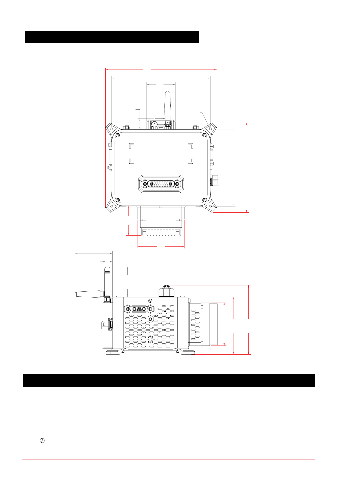
Figure 1.1.1 Top, Front, Left and Right views of PROTIUM-375
CHAPTER 1 | OVERVIEW
1OVERVIEW
1.1 PROTIUM-375 SYSTEM OVERVIEW
3
2
1
ITEM DESCRIPTION
1. Power/Signal receptacle 6. H2gas outlet connector
2. Cooling fan (x3) 7. Gas purge solenoid valve
3. Pressure sensor (x2) 8. H2gas inlet connector
4. Protective mask 9. Gas supply solenoid valve
5. Fuel cell stack
5
4
8
9
7
6

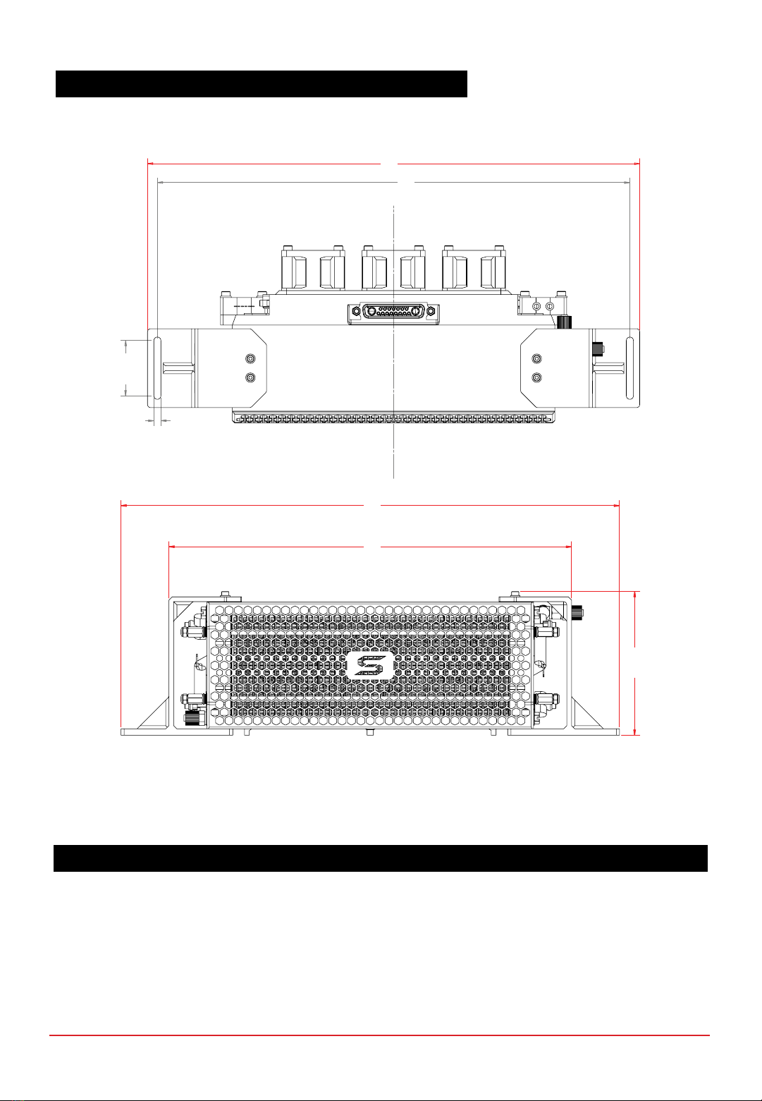
Figure 1.2.1 Top, Left and Right views of Electronic Controller
1.2 ELECTRONIC CONTROLLER
ITEM DESCRIPTION
10. DC-DC converter 15. Radio telemetry transmitter
11. Power/Signal header 16. Unregulated stack power out receptable
12. Mounting hole (x4) 17. Programming port
13. DC-DC power out (XT-60 female) 18. On-Off push button
14. External power supply receptable 19. Status LED
10
12
11
13
15
14
17
16
19
18
CHAPTER 1 | OVERVIEW

Figure 1.3.1 Supercapacitors pack
1.3 STANDARD ACCESSORIES
ITEM DESCRIPTION
20. Supercapacitor (x24) 22. DC-DC power out connector (XT-60 male)
21. Load connector (XT-90 female) 23. External power supply connector (XT-60 female)
20
21
22
23
CHAPTER 1 | OVERVIEW

Figure 1.3.2 External power supply cable, power/signal extension cable
ITEM DESCRIPTION
24. External power supply header 28. USB connector to PC
25. External power supply connector (XT-60 male) 29. Radio modem receiver
26. Power/signal extension cable (header) 30. Unregulated stack power out header
27. Power/signal extension cable (receptacle) 31. Free-end wires to load
1.3 STANDARD ACCESSORIES
25
27
29
31
24
26
28
30
CHAPTER 1 | OVERVIEW
*In compliance with Shell Eco Marathon competition rules, the fuel cell power output cable comes with ATOF®-
series 20A, 32V fast acting Blade Fuse (Part No. 0287020.PXCN) and fuseholder (Part No. 0FHA0002ZXJ).
0287020.PXCN
0FHA002ZXJ
*

ALL DIMENSIONS IN MM
A236.80 D31.00
B142.00 E40.00
C112.50 F86.80
1.4 MECHANICAL DIMENSION –PROTIUM-375
A
B
C
D
EF
CHAPTER 1 | OVERVIEW
ALL DIMENSIONS IN MM
A163.40 F113.00 K15.30
B145.00 G131.40 L44.22
C42.20 H43.10 M63.20
D16.25 I68.60 N85.00
E3.20 (4x) J55.58 O102.10
1.5 MECHANICAL DIMENSION –ELECTRONIC CONTROLLER
J
K
M N O
L
A
B
C
DE
F G
H
I
CHAPTER 1 | OVERVIEW
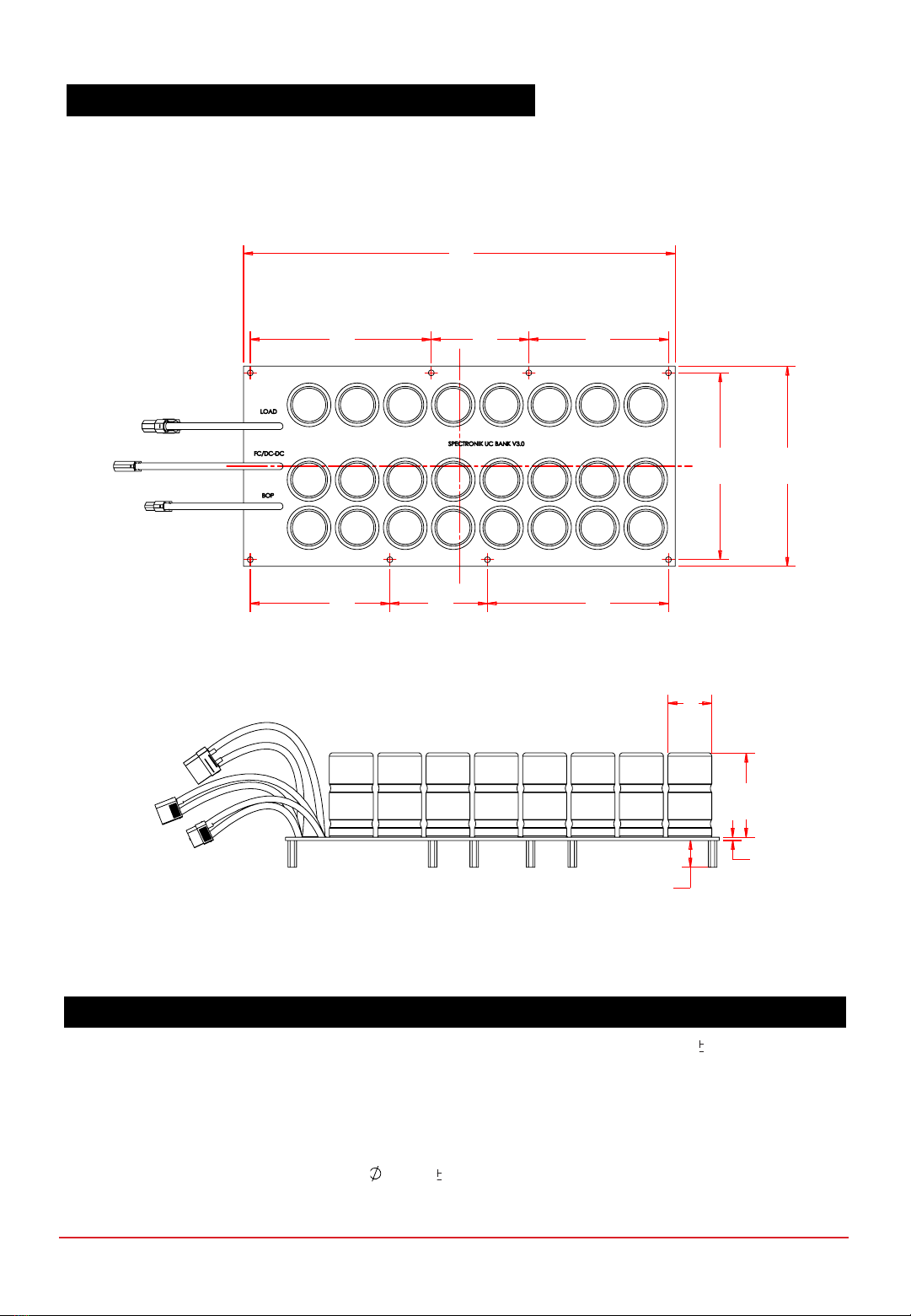
ALL DIMENSIONS IN MM
A323.00 F150.00 K62.50 1.0
B135.50 G104.50 L2.40
C73.00 H73.00 M20.00
D104.50 I135.50
E140.00 J33.00 1.0
1.6 MECHANICAL DIMENSION –STANDARD ACCESSORIES
A
B C D
G H I
EF
J
K
L
M
CHAPTER 1 | OVERVIEW
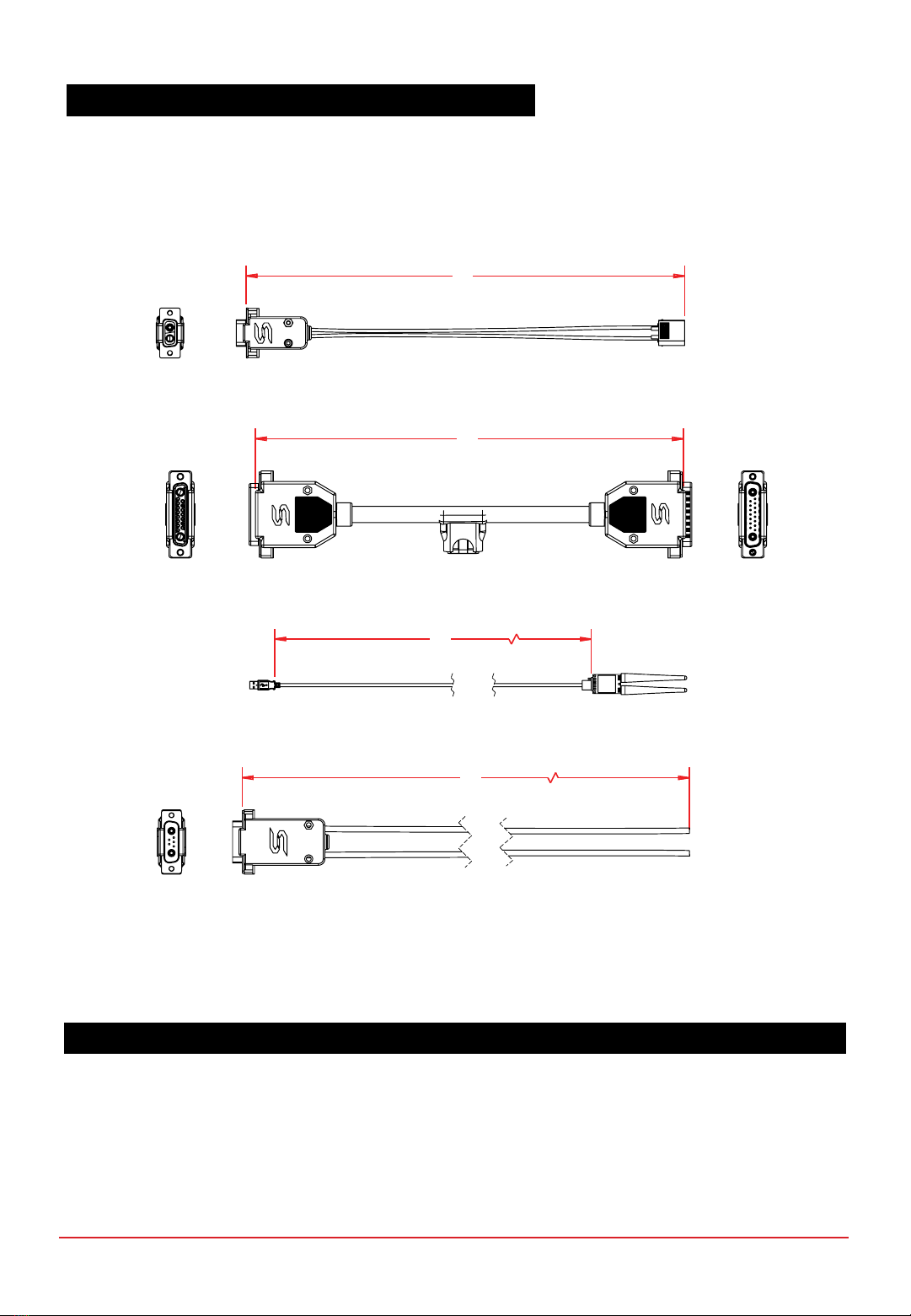
1.6 MECHANICAL DIMENSION –STANDARD ACCESSORIES
N
O
P
Q
ALL DIMENSIONS IN MM
N1000 P1800
O1000 Q1000
CHAPTER 1 | OVERVIEW

PROTIUM-375
cannot
be mounted in any orientation due to internal routings of the gas streams within the fuel
cell stack.
The fuel inlet must always be higher than the fuel outlet. The stack should also be level to ensure water does not
get trapped in the gas channels, obstructing the gas flow and causing potential performance drop and cell
damage.
Mount PROTIUM-375 in the recommended orientation above, using the mounting brackets provided.
For optimal oxidant and cooling airflows, it is also recommended that there is at least 15cm unobstructed
clearance in front of the protective mask and 30cm unobstructed clearance behind the cooling fans’ outlet.
Figure 1.7.1 Recommended orientation of PROTIUM-375
1.7 MOUNTING AND AIR CLEARANCE
CHAPTER 1 | OVERVIEW
ALL DIMENSIONS IN MM
A312.20 E312.20
B299.70 F252.20
C35.00 G90.10
D4.50
1.8 MECHANICAL DIMENSION –MOUNTING AND CLEARANCE
Figure 1.8.1 Dimensions of the mounting holes
A
B
C
D
E
F
G
CHAPTER 1 | OVERVIEW

Fuel Cell PROTIUM-375
Type PEM
No. of cells 50
Architecture Open cathode
Coolant Air cooled
Rated/gross power 375/450W
Rated/gross current 12.5/15A
Voltage output 30-45VDC
Start-up time <30s
Operating ambient temperature [0,35]oC
Operating altitude without power derating 1500m AGL
System weight 1,100g
Max dimension 238 x 113 x 87mm
Cell reaction area 21 sq.cm
Fuse ATOF®-series 20A, 32V fast acting Blade Fuse
Part No. 0287020.PXCN
Fuseholder Littelfuse Part No. 0FHA0002ZXJ
Fuel Supply
Hydrogen gas Dry, 99.999% purity
Delivery pressure 0.4-0.5barg (6-7 psig)
Fuel consumption @ rated power 4.4L/min
Gas tubing PTFE, 6 x 4
Supply & purge control Solenoid valves with integrated pressure sensor
Stack leakage checks Automated via integrated pressure sensors
Electronic Controller
Processor board FEATHER V1.2
External power supply requirement 15-90V, 50W max
Weight (including casing) 680g
Output connector XT-60 female (DC-DC regulated voltage)
Harting D sub DA-7W2 (stack unregulated voltage)
Warning & protections Low voltage, high/low temperature, high/low
pressure, low external power supply, stack leakage
Communication 868MHz ultra long range radio modem
Data acquisition (DAQ) software GUI PC app
Remote control Fan speed, manual purge, remote on-off
CHAPTER 2 | SPECIFICATIONS
2SPECIFICATIONS
2.1 TECHNICAL DATA SHEET
The output voltage (Vset) and output current (Iset) of the DC-DC converter can be changed according to the
user’s needs.This provides flexibility for the PROTIUM-375 to be compatible with various DC motor’s voltage
input range.To protect against current overdraw or to maintain the fuel cell’s output at its most optimum
power level, Iset can also be configured to limit the maximum allowable current output.Vset and Iset are factory
present during time of order for user convenience.
NOTE
DC-DC Converter
Type Non-isolated, half-brick, buck-boost
Input voltage 9-90VDC
Output voltage 0-90VDC user configurable
Output current 0-26A user configurable
Dimension 75 x 61 x 13mm
Weight 210g
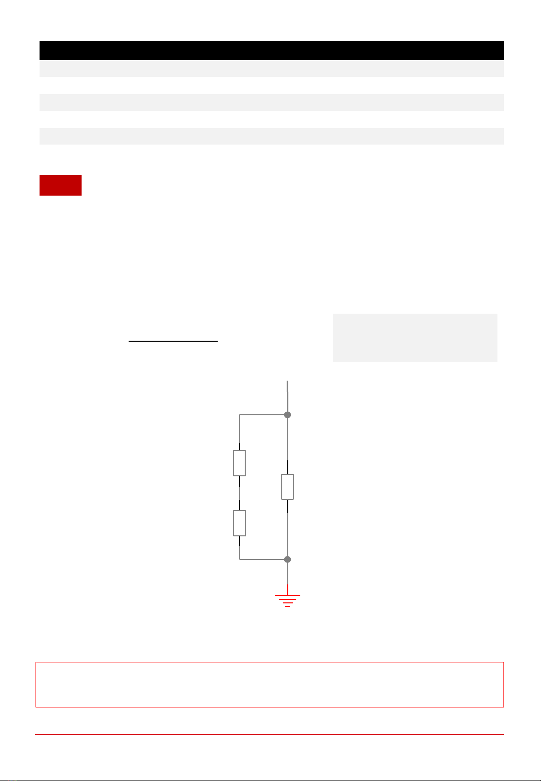
Figure 2.1.1 DC-DC converter’s PCB footprint of the resistors for Vset
Where
Vset = desired voltage output (0-90)
Vmax = 90
Rvset (Vset) =
11830 x Vmax
Vset + 0.058 x Vmax
[( ) ]
-10912 (Ω)
Vset
0805
R9
0805
R11
0805
R12
To change Vset, change the resistors on the DC-DC converter’s PCB board based on the following formula:
Caution:Changing Vset may require corresponding change in the number of supercapacitor cells in the
supercapacitors pack, as well as firmware update. Contact Spectronik for further advice.
CHAPTER 2 | SPECIFICATIONS

Iset can only be changed via the PC DAQ GUI app. Follow the instructions on Section 3 until step no.1 of
section 3.2. After the welcome header appears in the message box of the GUI, use the keyboard function of
the GUI and type the following command:
‘i’ <enter> ‘Iset’<enter>, where Iset is your desired current output limit (0-26A, limited to 375W).
For example:
‘i’ <enter> ‘5.0’ <enter>
If entered correctly, the message “I_set loaded successfully” will appear.Proceed to the next steps as per
instructions in section 3.2.
CHAPTER 2 | SPECIFICATIONS
Figure 2.1.2 GUI screenshot showing successful I_set of 5.0A

The Supercapacitors serve several functions:
1. To provide external power supply to the electronic controller during start-up.
2. To provide external power supply to the electronic controller and fuel cell’s balance-of-plant (BOP) when
the fuel cell stack carries out Current Pulsing*.
3. To provide additional power output to the motor load during peak acceleration and climbing, in ahybrid
parallel configuration to the fuel cell stack output.
4. To receive regenerative braking energy.
5. To be recharged by the fuel cell when excess power is available during cruising.
*The fuel cell stack performs periodic Current Pulsing (once every 15-30s, for a duration of around 100ms)
to rejuvenate its cell hydration and maintain optimal performance.During Current pulsing, power output from
fuel cell stack to load is momentarily cutoff for safety.
Supercapacitor detailed technical datasheet is attached in Annex A.
NOTE
Supercapacitors
Model BCAP0450 P270 S18
Nominal weight per supercapacitor 75g
Quantity 24 pcs in series
PCB mounting Included
Pack (24 pcs) weight 2.2kg
Pack (24 pcs) dimension 323 x 150 x 83mm
The standard pack consists of 24pcs of Supercapacitors in series, and suitable for use up to 60Vmotor.
For higher motor voltages, contact Spectronik for custom solutions.
CHAPTER 2 | SPECIFICATIONS

2.2 VI CURVE &HYDROGEN EFFICIENCY CURVE
Figure 2.2.1 Nominal polarization curve for a fully conditioned PROTIUM-375 at its Beginning-of-Life (BOL).
•Ambient temperature: 24oC
•Relative humidity: 60%
•H2supply pressure: 10psig
•Dead-ended operation
•Balance-of-plant (BOP) powered by fuel cell
•Tcell at 375W: 54oC
TEST CONDITIONS
0
50
100
150
200
250
300
350
400
450
500
0
5
10
15
20
25
30
35
40
45
50
0.0 2.0 4.0 6.0 8.0 10.0 12.0 14.0 16.0
Net Power (W)
Voltage (V)
Current (A)
CHAPTER 2 | SPECIFICATIONS

Figure 2.2.2 Hydrogen consumption and efficiency for a fully conditioned PROTIUM-375 at BOL.
•Hydrogen consumption is instantaneous reading taken from mass flowmeter at STP.
•PROTIUM-375 is most efficient in the 100-250Wrange which is the typical nominal
cruising power of Eco-Marathon vehicles.
NOTES
0.0
10.0
20.0
30.0
40.0
50.0
60.0
0.0
1.0
2.0
3.0
4.0
5.0
6.0
050 100 150 200 250 300 350 400 450 500
Efficiency (%)
Flowrate (L/min)
Power (W)
CHAPTER 2 | SPECIFICATIONS
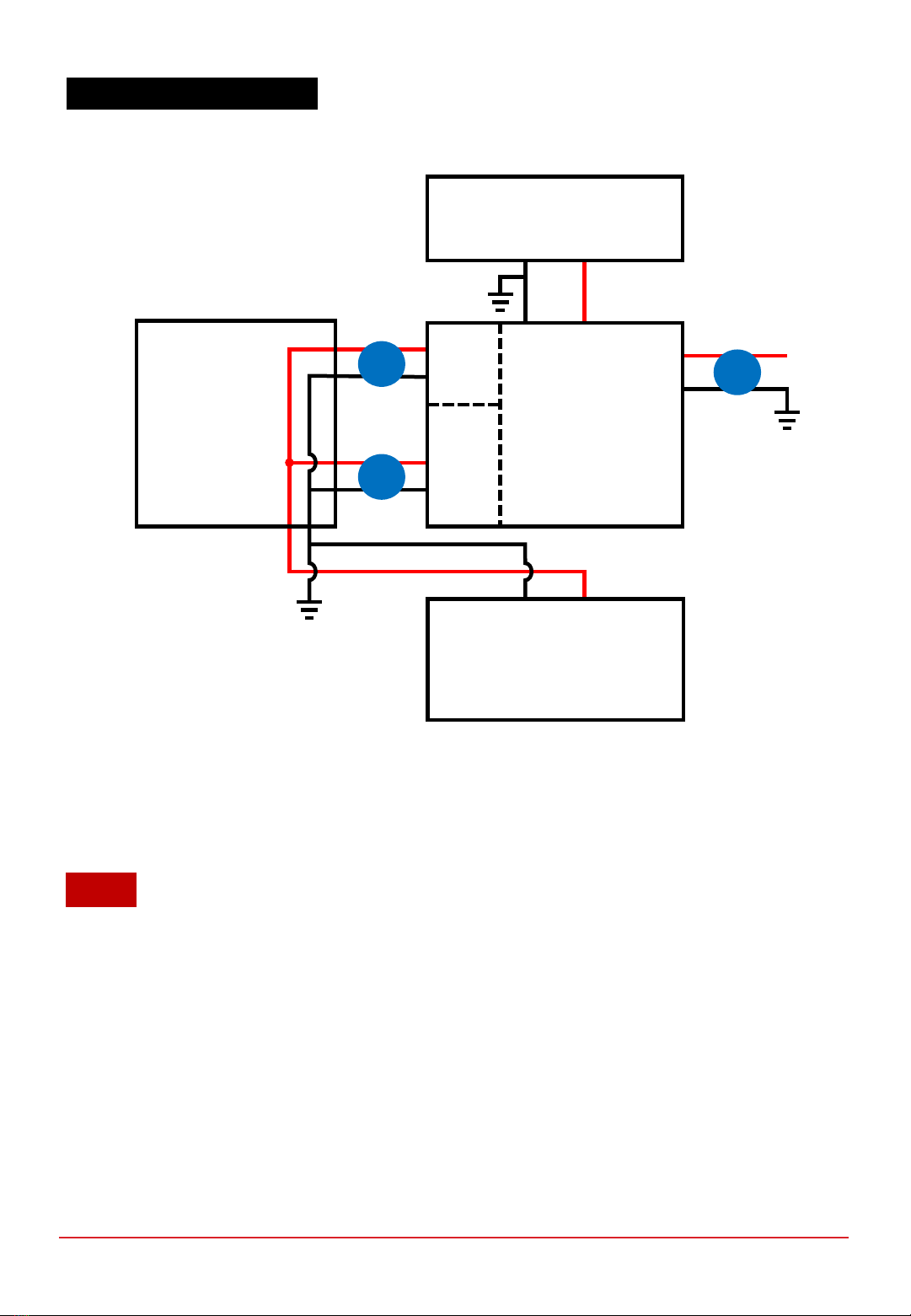
2.3 SYSTEM BLOCK DIAGRAM
1. An external power supply is required to initially turn on the electronic controller and power the fuel cell’s
Balance-of-plant (BOP). The Supercapacitors pack will be used as the external power supply.
2. It is recommended that the Iset of the DC-DC converter is set to limit the fuel cell’s output to 100-250W
range where its efficiency is the highest, although up to 375W can be obtained if desired.
3. Vset should be set to the required voltage of the DC motor load. Note that the Supercapacitors pack will be
recharged to Vset during operation if there is excess power available from the fuel cell.
4. For additional safety, power switches are recommended to be installed.
NOTE
CHAPTER 2 | SPECIFICATIONS
i. External power supply (Supercapacitors Pack)
ii. DC-DC regulated output (0-60VDC user configurable Vset, 375W max)
iii. Stack unregulated output (30-45VDC, 375W max)
Protium-375
Fuel Cell Stack
BOP
DC-DC
Fuel Cell
Electronic
Controller
Supercapacitors
Pack
i
LOAD
e.g. DC Motor
36V, 8.33A (300W)
ii
iii

1. The Supercapacitors pack is not charged when you receive it.Connect aDC power supply to any of the
Load connector (21), DC-DC power out connector (22), or External power supply connector
(23). Limit the current of the DC power supply to 1-2A and set the DC power supply voltage to be the
same as your eventual motor load voltage.
Tip
:this should also be the same voltage as DC-DC
converter’s Vset.Turn on the DC power supply to charge the supercapacitors pack.Charging is
completed when the voltage reaches Vset and the current output of the DC power supply is almost zero.
2. Mount PROTIUM-375 securely in the recommended orientation.
3. Connect your Hydrogen gas supply to the H2 gas inlet connector (8).Make sure that your Hydrogen
gas supply is OFF at this stage.
4. Connect the purge tubing to the H2 gas outlet connector (6).
Caution:
Channel the purge tubing
to the back of the cooling fans and far away from the front mask of the fuel cell stack.
5. Connect the power/signal receptacle (1) of the PROTIUM-375 to the power/signal header (11)
of the electronic controller, using the power signal extension cable (26/27).
6. Connect the DC-DC power out (13)of the electronic controller to its corresponding DC-DC power
out connector (22)on the supercapacitors pack.
7. Connect your DC motor load to the Load connector (21).
Tip
:check that the polarity is correct.
It is also advisable to put an ON/OFF switch at your load and ensure that it is turned OFF at
this time.
8. Turn on your PC and connect the radio modem receiver USB cable to a USB port. Download the
Spectronik Data Acquisition (DAQ) GUI PC application from the PROTIUM-375 product webpage.Install
the app and follow the instructions in its user guide.
Tip:
You can also use any serial data application like Hyperterminal.Set the parameters (57600
baud rate, 8data bit, No parity, 1stop bit).
Reminder:
Ensure that all gas tubing and electrical wire connections are firm and secure.
PROTIUM-375 is now ready to turn on.
CHAPTER 3 | OPERATING PROCEDURES
3OPERATING PROCEDURES
3.1 SETTING UP PROTIUM-375
Table of contents
Other Spectronik Camera Accessories manuals


