Spectrum SPB 5L14.4 Quick start guide

Sealed Performance Batteries
1 Ant Road, Yatala
Queensland, 4207
Tel: 1300 001 772
SPECTRUM BESS Installation Manual V2.1 – 22 Feb 23 1 | P a g e
SPECTRUM POWER STATION
INSTALLATION and OPERATIONAL GUIDE

Sealed Performance Batteries
1 Ant Road, Yatala
Queensland, 4207
Tel: 1300 001 772
SPECTRUM BESS Installation Manual V2.1 – 22 Feb 23 2 | P a g e
Contents
1. SPECTRUM POWER STATION OVERVIEW ....................................................................................... 3
2. SAFETY INSTRUCTIONS, LABELS AND WARNINGS .......................................................................... 4
3. SYSTEM CONFIGURATION ............................................................................................................... 5
4. INSTALLATION PROCEDURE ............................................................................................................ 6
4.1 Position Cabinet ...................................................................................................................... 6
4.2 Cable and Conduit connections .............................................................................................. 6
4.3 Installing the Batteries ............................................................................................................ 7
4.3 Fixing the Cabinet ................................................................................................................... 8
4.4 Switch Panel Layout ................................................................................................................ 9
4.5 Electrical Terminal Connections ............................................................................................ 10
4.6 Remote Sub-board (Optional) ............................................................................................... 10
4.7 Starting Battery System ........................................................................................................ 11
5. SHUT DOWN & STARTUP PROCEDURE ......................................................................................... 12
6. SERVICING THE AIR FILTERS .......................................................................................................... 13
7. LUX INVERTER PORTAL AND SMART PHONE APP ......................................................................... 14
8. LUX Inverter – Pairing of Wi-Fi Dongle to Router ......................................................................... 15
9. SPECTRUM CABINET - SINGLE LINE DIAGRAM .............................................................................. 17
10. WARRANTY................................................................................................................................ 18

Sealed Performance Batteries
1 Ant Road, Yatala
Queensland, 4207
Tel: 1300 001 772
SPECTRUM BESS Installation Manual V2.1 – 22 Feb 23 3 | P a g e
1. SPECTRUM POWER STATION OVERVIEW
The SPECTRUM Power Station is an Australian Made fully integrated battery energy storage system
(BESS) designed for hybrid application. The purpose of this guide is to provide installation and
operational procedures for the BESS.
The SPECTRUM is equipped with a LUX 5K Hybrid Inverter, 14.4 kWh battery storage, 8KW solar
capacity, 5kW grid export capacity and 4kW continuous emergency power supply.
Multiple SPECTRUM cabinets can also be paralleled for increased power including 3 phase
application (noting details are covered in another manual).
Specifications for single cabinet installation is given in the compliance plate below:

Sealed Performance Batteries
1 Ant Road, Yatala
Queensland, 4207
Tel: 1300 001 772
SPECTRUM BESS Installation Manual V2.1 – 22 Feb 23 4 | P a g e
2. SAFETY INSTRUCTIONS, LABELS AND WARNINGS
The following symbols are used within the integrated battery energy storage system:
WARNING SIGN
DESCRIPTION
This label is placed at the main metering panel
to show an energy storage system is present,
and also providing the UN No for the type of
battery chemistry – in this case Lithium Iron.
Warning of multiple supplie
s
Hazardous Voltage warning
Warning of energised supplies during grid
outage
Shutdown procedure – refer to section 5.
Rated voltages and currents marked up by the
installer depending on solar panels fitted.
Sealed Performance Batteries
1 Ant Road, Yatala
Queensland, 4207
Tel: 1300 001 772
SPECTRUM BESS Installation Manual V2.1 – 22 Feb 23 5 | P a g e
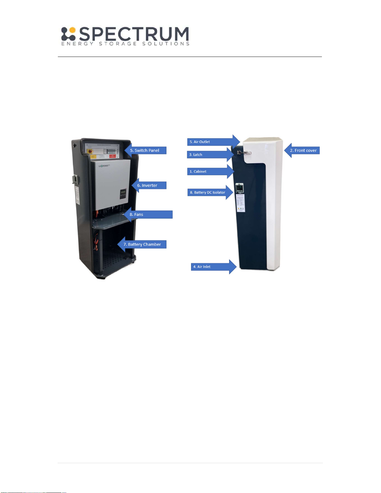
3. SYSTEM CONFIGURATION
The Spectrum Power Station is made up of the following components:
The Cabinet (1) is made from powder coated 3mm sheet aluminium and is suitable for installation
indoors or outdoors.
The Front Cover (2) can be removed via the side latches (3). The front cover can be tilted forwards
for easy access to the switch panel (5) and also can be lifted off the cabinet for open access.
The Switch Panel (5) contains pre-wired AC and DC switch gear and includes a 4 pole sub-board for
back-up (Offgrid) energy supply.
The Inverter (6) is mounted below the switch panel on the inverter bracket and secured at top and
bottom. The Inverter is pre-cabled via plug and play connectors and is fully programmed, apart from
the local Wi-Fi connection.
The Battery Chamber (7) houses up to 4 x Dyness B3 batteries giving a total of 14.4 kWh capacity.
The Battery DC Isolator (8) is located on the left side of the cabinet for quick access in case of an
emergency.
The Cabinet is ventilated via 2 x exhaust fans (8) located at the top of the Battery Chamber and
extracts air via the Air Inlet (4). Air is exhausted via the top of the Front Cover (5).

Sealed Performance Batteries
1 Ant Road, Yatala
Queensland, 4207
Tel: 1300 001 772
SPECTRUM BESS Installation Manual V2.1 – 22 Feb 23 6 | P a g e
4. INSTALLATION PROCEDURE
4.1 Position Cabinet
Locate the cabinet in an appropriate position, as per the battery installation guide issued by the
clean energy council AS 5139.
The cabinet is IP34 rated for indoor or outdoor
installation. A protective hood over the cabinet
is also recommended to minimise exposure to
driving rain and direct sunlight. In some
situations where direct sunlight cannot be
avoided the fans will run for longer duration.
The Cabinet should ideally be placed on a
concrete floor or pad, ensuring the material
behind the cabinet is not combustible. In some
case’s a non-combustible barrier may need to be installed with the minimum clearances as per the
diagram above.
If the cabinet is installed in a garage in line of vehicle traffic a bollard must be fitted to ensure its not
accidentally damaged.
The cabinet can be positioned with its back against a wall, also noting the conduit entry is from the
rear.
The cabinet should also be at least 600m from any heat source such as a H/W system.
4.2 Cable and Conduit connections
Run conduits as necessary into the rear cavity of the cabinet for:
a. Solar pv
b. Grid connection
c. Backup Power circuits
Terminate the cables into the required isolators as indicated on the Electrical Terminal Connections
in section 4.5 and Attachment A.
Screw the plastic moulding back into place via 4 x screws and place a silicon bead around the edge to
inhibit water ingress.

Sealed Performance Batteries
1 Ant Road, Yatala
Queensland, 4207
Tel: 1300 001 772
SPECTRUM BESS Installation Manual V2.1 – 22 Feb 23 7 | P a g e
4.3 Installing the Batteries
Up to 4 x Dyness B3 batteries can be mounted in the cabinet as follows:
1. Place the bottom battery on the rubber feet located in the battery chamber and slide the
battery all the way to the back.
2. Drill 4 x battery mounting holes into the aluminium vertical rails using a 5mm drill. The
screws provided with the batteries will self-tap into the holes, ensuring not to overtighten.
3. Attach the inverter cable (coiled in battery chamber) to CANBUS IN port on the top battery.
4. Interconnect the short comms cables (provided in the battery box) between each battery
starting at the bottom battery from CANBUS IN to CANBUS OUT.
5. Attach the RED Positive battery cable (coiled in cabinet) to the top battery left side.
6. Attach the BLACK Negative battery lead (coiled in cabinet) from inverter to the bottom
battery right side.
7. Connect the parallel cables (provided in the battery box) between the battery packs, positive
to positive and negative to negative.
8. Attach the earth lead from the inverter (coiled in cabinet) to bottom battery.
9. Interconnect earth battery earths with GREEN leads provided in the battery box.
10. Zip tie all leads to ensure they are not hanging out of the cabinet, also noting there is only a
small amount of space between the battery and the front cover.
11. Ensure the master battery (top) has dip switch setting - off/off/on/off.
12. Ensure all slave batteries have dip switch setting - off/off/off/off.

Sealed Performance Batteries
1 Ant Road, Yatala
Queensland, 4207
Tel: 1300 001 772
SPECTRUM BESS Installation Manual V2.1 – 22 Feb 23 8 | P a g e
4.3 Fixing the Cabinet
To secure the cabinet 3 methods are available:
Method 1 - Attach the cabinet to a back wall via
fixing screws behind the DIN panel. It may be
necessary to put a spacer in behind the cabinet
where there is an offset to the wall.
Method 2 - In the case of mounting on a raised floor
or a trailer the cabinet can be bolted via the feet
under the cabinet.
Method 3 - With the batteries fitted and cabinet
positioned on a stable concrete surface, the system
weighs in at over 100kG and fixing points may not be
necessary, especially if located in lockable area.

Sealed Performance Batteries
1 Ant Road, Yatala
Queensland, 4207
Tel: 1300 001 772
SPECTRUM BESS Installation Manual V2.1 – 22 Feb 23 9 | P a g e
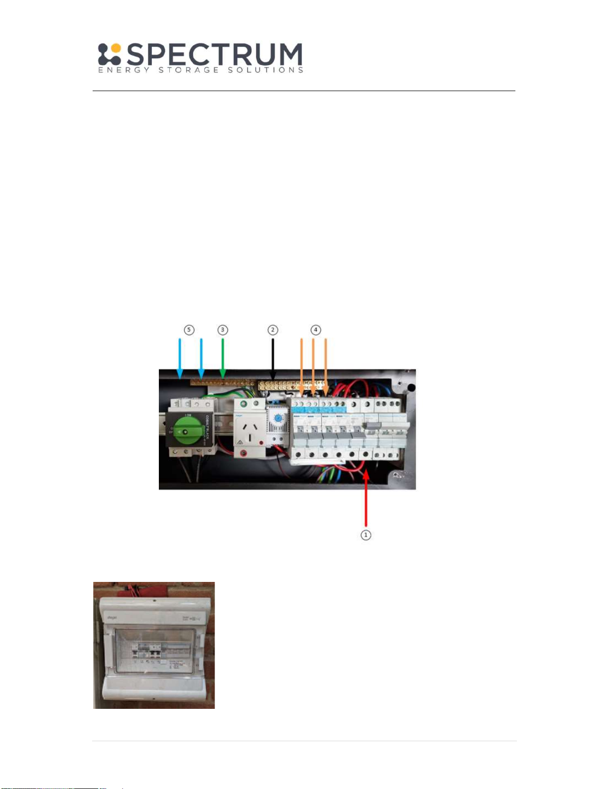
4.4 Switch Panel Layout
1) Solar DC Isolator – pre-cabled to the inverter. Connect to the PV strings to top of isolator as
per SLD diagram.
2) Change Over Switch – this switch is pre-cabled.
- Switch to “EPS” position for Emergency Power Supply from the battery
- Switch to “Mains ” for alternative supply from mains or Generator
Note – for some installations the Change-over switch may be located in a separate sub-
board.
3) Individual circuit breakers – connect these breakers to power the individual loads as per the
SLD diagram for the project.
4) Temp Control – (located behind the DIN cover) controls the ventilation fan in the top lid of
the power cabinet. It is normally set to 40 deg C.
5) Inverter EPS (Off-Grid) – pre-cabled to the inverter, supplies power to the backup / sub
circuits – refer to Error! Reference source not found.
6) Inverter In (Mains) – pre-cabled to the inverter input, requires connection to the Grid supply
– refer to Error! Reference source not found.
7) GPO outlet for 4G Wifi modem
8) Energy Management System (optional)
Sealed Performance Batteries
1 Ant Road, Yatala
Queensland, 4207
Tel: 1300 001 772
SPECTRUM BESS Installation Manual V2.1 – 22 Feb 23 10 | P a g e
Note – The Battery DC Isolator is on the left side of the cabinet.
4.5 Electrical Terminal Connections
Connect the Cabinet as follows:
Connect Grid Active (1), Neutral (2) and Earth (3) to the grid supply
Connect the required essential loads (4) to the sub circuits.
Connect the Solar PV1 and PV2 strings (5)
4.6 Remote Sub-board (Optional)
Where the cabinet is located some distance away from the electrical
switch board, it may be necessary to install a remote sub-board. In
this case it is most likely the change over switch would be located in
the sub-board, rather than in the battery cabinet. Please refer to the
following section for wiring details: Error! Reference source not
found..
Table of contents


