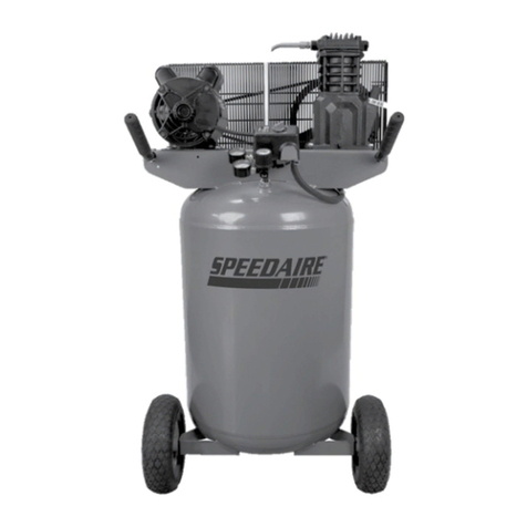
Speedaire 4UP73 Instructions for use

Form 5S4280
Description
Speedaire twin cylinder, low maintenance, oil-less portable air compressor is designed
for home, farm and medium duty industrial uses with a 50/50 duty cycle. The 3.5 HP
pump and motor assembly on a 20 gallon capacity air tank is equipped with check valve,
unloader valve, pressure switch, safety valve, air regulator, and tank pressure gauge.
Motor includes automatic thermal overload protection. UL listed.
Printed in U.S.A.
03465
0998/239/VCPVP
®
Specifications
Motor HP ............................................... 3.5
Cylinders ............................................. Two
Air Delivery - SCFM @ 90 psi................. 5.9
@ 40 psi ....................8.0
Maximum Air Pressure (psi) .................. 135
Compressor RPM ............................... 1725
Tank Size (Gallons) ................................. 20
Voltage @ 60 Hz, 1-Phase ............. 120/240
Amperage (Amps) ............................. 15/7.5
Overall Dimensions
Model 4UP73.....
L W H Weight
35.75” 19.06” 32.75"
123 lbs.
Figure 1
Unpacking
After unpacking the unit, inspect carefully
for any damage that may have occurred
during transit. Check for loose, damaged
or missing parts.
Please read and save these instructions. Read carefully before attempting to assemble, install, operate or maintain the
product described. Protect yourself and others by observing all safety information. Failure to comply with instructions
could result in personal injury and/or property damage! Retain instructions for future reference.
Operating Instructions & Parts Manual 4UP73
Speedaire Permanently
Lubricated Twin Cylinder
Air Compressors
®
Danger
indicates an
imminently hazardous situation
which, if not avoided, WILL result
in death or serious injury.
Important
safety
information - A hazard that
might cause serious injury or
loss of life.
Caution
indicates a
potentially hazardous situation
which, if not avoided, MAY
result in minor or moderate
injury.
NOTE: Note indicates important
information, that if not followed,
may cause damage to equipment.
Safety Guidelines
This manual contains information
that is very important to know
and understand. This information
is provided for SAFETY and to
PREVENT EQUIPMENT PROB-
LEMS. To help recognize this in-
formation, observe the following
symbols.
E
S
P
A
N
O
L
F
R
A
N
C
A
I
S
E
N
G
L
I
S
H
#721Y
D21100-0

2
E
N
G
L
I
S
H
RISK OF BURSTING
RISK OF
EXPLOSION OR FIRE
AIR TANK
THE FOLLOWING CONDITIONS COULD LEAD
TO A WEAKENING OF THE TANK, AND RESULT
IN A VIOLENT TANK EXPLOSION:
1. FAILURE TO PROPERLY DRAIN
CONDENSED WATER FROM THE TANK,
CAUSING RUST AND THINNING OF THE
STEEL TANK.
2. MODIFICATIONS OR ATTEMPTED
REPAIRS TO THE TANK.
3. UNAUTHORIZED MODIFICATIONS TO THE
PRESSURE SWITCH, SAFETY VALVE, OR
ANY OTHER COMPONENTS WHICH
CONTROL TANK PRESSURE.
ATTACHMENTS & ACCESSORIES
EXCEEDING THE PRESSURE RATING OF AIR
TOOLS,SPRAY GUNS, AIR OPERATED ACCES-
SORIES, TIRES AND OTHER INFLATABLES CAN
CAUSE THEM TO EXPLODE OR FLY APART,
AND COULD RESULT IN SERIOUS INJURY.
1. IT IS NORMAL FOR ELECTRICAL
CONTACTS WITHIN THE MOTOR AND
PRESSURE SWITCH TO SPARK.
2. IF ELECTRICAL SPARKS FROM
COMPRESSOR COME INTO CONTACT WITH
FLAMMABLE VAPORS, THEY MAY IGNITE,
CAUSING FIRE OR EXPLOSION.
3. RESTRICTING ANY OF THE COMPRESSOR
VENTILATION OPENINGS WILL CAUSE
SERIOUS OVERHEATING AND COULD
CAUSE FIRE.
1. DRAIN TANK DAILY OR AFTER EACH
USE. IF TANK DEVELOPS A LEAK,
REPLACE IT IMMEDIATELY WITH A NEW
TANK OR NEW COMPRESSOR OUTFIT.
2. NEVER DRILL INTO, WELD, OR MAKE
ANY MODIFICATIONS TO THE TANK OR
ITS ATTACHMENTS.
3. THE TANK IS DESIGNED TO WITHSTAND
SPECIFIC OPERATING PRESSURES.
NEVER MAKE ADJUSTMENTS OR
PARTS SUBSTITUTIONS TO ALTER THE
FACTORY SET OPERATING PRESSURES.
FOLLOW THE EQUIPMENT MANUFACTUR-
ERS RECOMMENDATION AND NEVER
EXCEED THE MAXIMUM ALLOWABLE
PRESSURE RATING OF ATTACHMENTS.
NEVER USE COMPRESSOR TO INFLATE
SMALL LOW-PRESSURE OBJECTS SUCH
AS CHILDREN’S TOYS, FOOTBALLS,
BASKETBALLS, ETC.
1. ALWAYS OPERATE THE COMPRESSOR
IN A WELL VENTILATED AREA FREE OF
COMBUSTIBLE MATERIALS, GASOLINE
OR SOLVENT VAPORS.
2. IF SPRAYING FLAMMABLE MATERIALS,
LOCATE COMPRESSOR AT LEAST 20
FEET AWAY FROM SPRAY AREA. AN
ADDITIONAL LENGTH OF HOSE MAY BE
REQUIRED.
STORE FLAMMABLE MATERIALS IN A
SECURE LOCATION AWAY FROM
COMPRESSOR.
3. NEVER PLACE OBJECTS AGAINST OR
ON TOP OF COMPRESSOR. OPERATE
COMPRESSOR IN AN OPEN AREA AT
LEAST 12 INCHES AWAY FROM ANY
WALL OR OBSTRUCTION THAT WOULD
RESTRICT THE FLOW OF FRESH AIR TO
THE VENTILATION OPENINGS.
HAZARD WHAT CAN HAPPEN HOW TO PREVENT IT
IMPROPER OPERATION OR MAINTENANCE OF THIS PRODUCT COULD RESULT IN SERIOUS INJURY
AND PROPERTY DAMAGE. READ AND UNDERSTAND ALL WARNINGS AND OPERATING INSTRUC-
TIONS BEFORE USING THIS EQUIPMENT.
Speedaire Permanently Lubricated
Twin Cylinder Air Compressor
Speedaire Operating Instructions and Parts Manual 4UP73
®

®
3
E
N
G
L
I
S
H
Speedaire Operating Instructions and Parts Manual
Model 4UP73
HAZARD
RISK OF
ELECTRICAL SHOCK
RISK FROM FLYING OBJECTS
RISK TO BREATHING
RISK FROM MOVING PARTS
RISK OF FALLING
WHAT CAN HAPPEN
1. YOUR AIR COMPRESSOR IS POWERED
BY ELECTRICITY. LIKE ANY OTHER
ELECTRICALLY POWERED DEVICE, IF IT IS
NOT USED PROPERLY IT MAY CAUSE
ELECTRIC SHOCK.
2. REPAIRS ATTEMPTED BY UNQUALIFIED
PERSONNEL CAN RESULT IN SERIOUS
INJURY OR DEATH BY
ELECTROCUTION.
3. ELECTRICAL GROUNDING: FAILURE TO
PROVIDE ADEQUATE GROUNDING TO
THIS PRODUCT COULD RESULT IN
SERIOUS INJURY OR DEATH FROM
ELECTROCUTION. SEE GROUNDING
INSTRUCTIONS.
THE COMPRESSED AIR STREAM CAN
CAUSE SOFT TISSUE DAMAGE TO
EXPOSED SKIN AND CAN PROPEL DIRT,
CHIPS, LOOSE PARTICLES, AND SMALL
OBJECTS AT HIGH SPEED, RESULTING IN
PROPERTY DAMAGE OR PERSONAL
INJURY.
1. THE COMPRESSED AIR FROM YOUR
COMPRESSOR IS NOT SAFE FOR
BREATHING! THE AIR STREAM MAY
CONTAIN CARBON MONOXIDE, TOXIC
VAPORS, OR SOLID PARTICLES.
2. SPRAYED MATERIALS SUCH AS PAINT,
PAINT SOLVENTS, PAINT REMOVER,
INSECTICIDES, WEED KILLERS, ETC.
CONTAIN HARMFUL VAPORS AND
POISONS.
1. MOVING PARTS CAN CAUSE SERIOUS
INJURY OR DAMAGE IF THEY COME
INTO CONTACT WITH YOU OR YOUR
CLOTHING.
2. ATTEMPTING TO OPERATE OR REPAIR
COMPRESSOR WITH PROTECTIVE
SHROUDS REMOVED CAN EXPOSE
YOU TO MOVING PARTS AND
ELECTRICAL SHOCK.
3. THE COMPRESSOR CYCLES AUTO-
MATICALLY WHEN THE PRESSURE
SWITCH IS IN THE ON/AUTO POSITION.
A PORTABLE COMPRESSOR CAN FALL
FROM A TABLE, WORKBENCH OR ROOF
CAUSING DAMAGE TO THE COMPRES-
SOR WHICH COULD EXPOSE YOU TO
HAZARDOUS MOVING OR ELECTRICAL
PARTS.
HOW TO PREVENT IT
1. NEVER OPERATE THE COMPRESSOR
OUTDOORS WHEN IT IS RAINING OR IN
WET CONDITIONS
NEVER OPERATE COMPRESSOR WITH
COVER COMPONENTS REMOVED OR
DAMAGED.
2. ANY ELECTRICAL WIRING OR REPAIRS
REQUIRED ON THIS PRODUCT SHOULD
BE PERFORMED BY AUTHORIZED
SERVICE CENTER PERSONNEL IN
ACCORDANCE WITH THE UNITED
STATES NATIONAL AND LOCAL
ELECTRICAL CODES.
3. MAKE CERTAIN THAT THE ELECTRICAL
CIRCUIT TO WHICH THE COMPRESSOR
IS CONNECTED PROVIDES PROPER
ELECTRICAL GROUNDING, CORRECT
VOLTAGE AND ADEQUATE FUSE
PROTECTION.
ALWAYS WEAR ANSI Z87.1 APPROVED
SAFETY GLASSES WITH SIDE SHIELDS
WHEN USING THE COMPRESSOR.
NEVER POINT ANY NOZZLE OR SPRAYER
TOWARD ANY PART OF THE BODY OR AT
OTHER PEOPLE OR ANIMALS.
1. NEVER INHALE AIR FROM THE
COMPRESSOR EITHER DIRECTLY OR
FROM A BREATHING DEVICE
CONNECTED TO THE COMPRESSOR.
2. WORK IN AN AREA WITH GOOD CROSS-
VENTILATION. READ AND FOLLOW THE
SAFETY INSTRUCTIONS PROVIDED ON
THE LABEL OR SAFETY DATA SHEETS
FOR THE MATERIAL YOU ARE
SPRAYING. USE A NIOSH/MSHA
APPROVED RESPIRATOR DESIGNED
FOR USE WITH YOUR SPECIFIC
APPLICATION.
1. DO NOT REMOVE THE PROTECTIVE
COVERS FROM THIS PRODUCT. NEVER
OPERATE THE COMPRESSOR WITH
GUARDS OR COVERS WHICH ARE
DAMAGED OR REMOVED.
2. ANY REPAIRS REQUIRED ON THIS
PRODUCT SHOULD BE PERFORMED BY
AUTHORIZED SERVICE CENTER
PERSONNEL.
3. ALWAYS TURN OFF THE COMPRESSOR,
BLEED PRESSURE FROM THE AIR
HOSE AND TANK, AND UNPLUG FROM
ELECTRICAL OUTLET BEFORE PER-
FORMING MAINTENANCE OR ATTACH
ING TOOLS AND ACCESSORIES.
ALWAYS OPERATE COMPRESSOR IN A
STABLE SECURE POSITION TO PREVENT
ACCIDENTAL MOVEMENT OF THE UNIT.
NEVER OPERATE COMPRESSOR ON A
ROOF OR OTHER ELEVATED POSITION.
USE ADDITIONAL AIR HOSE TO REACH
HIGH LOCATIONS.

4
E
N
G
L
I
S
H
Speedaire Operating Instructions and Parts Manual 4UP73
If any of the above conditions cannot be
met, or if operation of the compressor
repeatedly causes interruption of the
power, it may be necessary to operate it
from a 20 amp circuit. It is not necessary
to change the cord set.
VOLTAGE AND CIRCUIT PROTECTION
Refer to the specification chart for voltage
and circuit protection requirements of
your compressor. Use only a fuse or circuit
breaker that is the same rating as the
branch circuit the air compressor is
operated on. If the compressor is con-
nected to a circuit protected by fuses, use
only dual element time delay fuses.
GROUNDING INSTRUCTIONS
Improper
grounding can
result in electrical shock. In the event
of a short circuit, grounding reduces
risk of shock by providing an escape
wire for the electric current. Air
compressor must be properly
grounded.
1. Air compressor is equipped with a
cord having a ground wire with an
appropriate grounding plug. Plug
must be used with an outlet that has
been installed and grounded in
accordance with all local codes and
ordinances. Outlet and plug must
have the same configuration. DO
NOT USE AN ADAPTER.
2. Do not modify the provided plug. If it
does not fit the available outlet, the
correct outlet should be installed by a
qualified electrician.
3. Inspect plug and cord before each
use. Do not use if there are signs of
damage.
Installation
TOOLS NEEDED FOR ASSEMBLY
• 9/16" socket or open end wrench for
attaching the wheels or removing
shipping boards
• 3/8" open end wrench or socket to
tighten handle screws
INSTALLING WHEELS AND
ISOLATORS
The wheels and
handle do not
provide adequate clearance,
stability or support for pulling the
unit up and down stairs or steps.
HAZARD WHAT CAN HAPPEN
TOUCHING EXPOSED METAL SUCH AS
THE COMPRESSOR HEAD OR OUTLET
TUBE CAN RESULT IN SERIOUS BURNS.
HOW TO PREVENT IT
NEVER TOUCH ANY EXPOSED METAL
PARTS ON COMPRESSOR DURING OR
IMMEDIATELY AFTER OPERATION.
COMPRESSOR WILL REMAIN HOT FOR
SEVERAL MINUTES AFTER OPERATION.
EXTENSION CORD
To avoid voltage drop and power loss to
the motor use extra air hose instead of an
extension cord. If an extension cord must
be used, be sure it is:
1. A 3-wire extension cord that has a
3-blade grounding plug, and a 3-slot
receptacle that will accept the plug
on the product.
2. In good condition.
3. No longer than 50 feet.
4. 12 gauge (AWG) or larger. Wire size
increases as gauge number
decreases. 10 AWG and 8 AWG may
also be used. (DO NOT USE A 14
OR 16 AWG.)
Certain air compres-
sor models can be
converted to 240 volts from 120 volt
operation. When converting a specific
model to 240 volt operation, the
attached three-prong 120 volt plug
must be replaced with the three-
prong 240 volt plug (purchase locally)
or order line cord Part No. K-0084.
Some models have a dual voltage
motor, 120 and 240 volt. They are wired
for 120 volt but can be converted to 240
volt operation. Instructions for converting
these motors for operation at 240 volt can
be found printed on the label attached to
the side of the motor.
Compressor can be
operated on a 15
amp circuit if:
1. Voltage supply to circuit is normal.
2. Circuit is not used to supply any
other electrical needs (lights,
appliances, etc.)
3. Extension cords comply with
specifications in owners manual.
4. Circuit is equipped with 15 amp
circuit breaker or 15 amp time
delay fuse. Use a Fusetron Type
"T" time delay fuse.
It may be neces-
sary to brace or
support one end of the outfit when
attaching the wheels and the isola-
tors because the air compressor will
have a tendency to tip.
1. Install one shoulder bolt and one nut
for each wheel using upper bolt
hole. Tighten securely. The outfit
will sit level if the wheels are
properly installed.
2. Install isolators to the front bracket.
LOCATION OR AIR COMPRESSOR
Locate air compressor in a clean, dry,
well ventilated area. Air filter must be
kept clear of obstructions, which could
reduce air delivery of the air
compressor. The air compressor should
be located at least 12” away from the
wall or other obstructions that will
interfere with air flow. Air compressor
head and shroud are designed to allow
proper cooling. If humidity is high, air
filter can be installed to remove
excessive moisture. Follow air filter
instructions for proper installation.
Speedaire Permanently Lubricated
Twin Cylinder Air Compressor
®
RISK OF BURNS

®
5
E
N
G
L
I
S
H
Regulator
Pressure
Relief Valve
(Not Shown)
Pressure
Switch
On/Off
Lever
A
ir
Compressor
Pump
Pressure
Gauge
Tank
Pressure
Gauge
Safety
Valve
Check Valve Drain Valve
Speedaire Operating Instructions and Parts Manual
Model 4UP73
Installation (Continued)
Risk of electrical
shock. If repairing
or replacing cord or plug, the
grounding wire must be kept
separate from the current-carrying
wires. Never connect the grounding
wire to a flat blade plug terminal.
(The grounding wire has insulation
with an outer surface that is green
with or without yellow stripes.)
White
Wire
Ground
15 AMP Plug
Grounded
Outlet
Outlet
Grounding
Pin
Operation
AIR COMPRESSOR PUMP
To compress air, the pistons move up and
down in the cylinder. Air is drawn in
through the air intake valves on the
downstroke of the pistons. Exhaust valve
remains closed. On the upstroke of the
pistons, air is forced out through the
exhaust valve, through the outlet tubes,
through the check valve, and into the air
tank. Working air is not available until the
compressor has raised the air tank pressure
above that required at the air outlet.
CHECK VALVE
When the air compressor is operating,
the check valve is "open", allowing
compressed air to enter the air tank.
When the air compressor reaches
"cut-out" pressure, the check valve
closes, allowing air pressure to remain
inside the air tank.
PRESSURE RELEASE VALVE
The pressure release valve located on the
side of the pressure switch, is designed to
automatically release compressed air from
the compressor head and the outlet tube
when the air compressor reaches "cut-out"
pressure or is shut off.
Figure 2
BREAK-IN PROCEDURES
This procedure is only required the first
time the air compressor is put into service
and when the check valve has to be
replaced.
1. Set the pressure switch OFF/AUTO
lever to the OFF position.
2. Plug power cord into the correct
branch circuit receptacle.
3. Turn regulator clockwise, opening it
fully, to prevent air pressure build-up
in the tank.
4. Move the OFF/AUTO lever to
AUTO. Compressor will start.
5. Run the compressor for 15 minutes.
Make sure the regulator is open and
there is no tank pressure buildup.
6. After 15 minutes, close the regulator
by turning it counter-clockwise. Air
tank will fill to cut-out pressure and
then the motor will stop.
Motor will not be able to start if the air
is not released. The pressure release
valve allows the motor to restart freely.
After the motor stops running air will
escape from the pressure release valve.
No air should be heard leaking when
the motor is running.
PRESSURE SWITCH
The pressure switch automatically starts
the motor when the air tank pressure
drops below the factory set "cut-in"
pressure. When the air tank pressure
reaches the factory set "cut-out"
pressure the pressure switch
automatically stops the motor.
SAFETY VALVE
If the pressure switch does not shut off
the air compressor at its cut-out
pressure setting, the safety valve will
protect against high pressure by
"popping off" at its preset pressure.
REGULATOR
Air pressure coming from the air tank is
controlled by the regulator knob. Turn
the knob clockwise to increase pressure
and counter-clockwise to decrease
pressure. To avoid minor readjustments
after making a change in pressure
setting, always approach the desired
pressure from a lower pressure. When
reducing from a higher to a lower
setting, first reduce to a pressure lower
than is desired, then raise the pressure
to the desired setting. The outlet
regulated air pressure may need to be
adjusted while operating, depending on
the air requirements of the accessory.
OUTLET PRESSURE GAUGE
The outlet pressure gauge indicates the
air pressure available at the outlet side
of the regulator. Pressure is controlled
by the regulator and is always equal to
or less than the tank pressure. See
"Operating Procedures."
TANK PRESSURE GAUGE
The reserve air pressure in the tank is
indicated by the tank pressure gauge.
Figure 3

6
E
N
G
L
I
S
H
Speedaire Operating Instructions and Parts Manual 4UP73
1. Compress the rear slotted end of each
of the two pins holding filter in place.
2. Pull pin forward releasing the filter
itself.
3. Clean (Wash in mild detergent.)
4. Reinstall a clean filter, place in
position, and push retaining pins into
holes securing filter.
Speedaire Permanently Lubricated
Twin Cylinder Air Compressor
®
Operation (Continued)
MOTOR
Motor has an automatic reset thermal
overload protector. If motor overheats for
any reason, overload protector will shut off
motor. Motor must be allowed to cool
down before restarting. Compressor will
automatically re-start after motor cools.
Low voltage may cause:
1. Overload protector to frequently shut
off the motor.
2. Motor not to get up to full power or
speed.
3. Fuses blow out when starting the
motor.
4. Lights dim and remain dim when
motor is started and running.
SAFETY VALVE - INSPECTION
If safety valve does
not work properly,
over-pressurization may occur, causing
air tank rupture or an explosion.
Occasionally pull ring on safety valve
to make certain safety valve operates
freely. If the valve is stuck or does not
operate smoothly, replace with the
same type or valve.
Filter
Figure 4
LUBRICATION
Compressor does not require any
lubrication. All metal bearings are
permanently lubricated and the
compression cylinder/piston/ring area is
specifically designed to require no
lubrication.
NOTE: If drain valve is plugged, release all
air pressure. Remove valve, clean, then
reinstall valve.
6. After water has been drained, close
drain valve. Air compressor can now
be stored.
Hot surfaces. Risk of
burn. Compressor
heads are exposed when filter cover is
removed. Allow compressor to cool
prior to servicing.
Maintenance
Unit cycles auto-
matically when
power is on. When performing
maintenance, you may be exposed to
voltage sources, compressed air or
moving parts. Before performing any
maintenance or repair, unplug the
power cord and bleed off all air
pressure.
AIR FILTER INSPECTION
NOTE: Keep the air filter clean at all times.
Do not operate the compressor with the
air filter removed. A dirty filter will not
allow the compressor to operate at full
capacity. Before using the compressor,
check the air filter to be sure it is clean. To
remove and clean or replace the foam air
filter:
Water will condense
in air tank. If not
drained, water will corrode and
weaken air tank causing a risk of air
tank rupture.
With tank pressure at approximately
20 psi, open the drain valve and tip the
outfit allowing all moisture to drain.
ON/AUTO - OFF SWITCH
Turn this switch ON to provide auto-
matic power to the pressure switch and
OFF to remove power at the end of each
use.
AIR INTAKE FILTER
This filter is designed to clean air
coming into the pump. This filter MUST
always be clean and ventilation open-
ings free from obstructions. See
"Maintenance".
Operating Procedures
STARTING
1. Before attaching air hose or
accessories, make sure the
OFF/AUTO lever is set to OFF and
the air regulator is closed. (Turn
counter-clockwise to close.)
2. Attach hose and accessories.
DRAIN VALVE
The drain valve is located at the base of
the air tank and is used to drain conden-
sation at the end of each use.
MOTOR THERMAL OVERLOAD
PROTECTOR
The electric motor has an automatic
thermal overload protector. If the motor
overheats for any reason, the thermal
overload protector will shut off the
motor. The motor must be allowed to
cool before restarting.
6. Always operate air compressor in
well-ventilated areas (free of
gasoline, flammable paint or solvent
vapors). Do not operate the
compressor near a spray area.
STOPPING
1. Set the OFF/AUTO lever to OFF.
2. Turn the regulator counter-clockwise
and set the outlet pressure to zero.
3. Remove air tool or accessory.
4. Open regulator and allow air to
slowly bleed from the tank. Close
regulator when tank pressure is
approximately 20 psi.
5. Drain water from air tank.
Incorrect use can
cause bursting,
fire or explosion hazards. Carefully
follow steps 3, 5, and 6 each time the
compressor is used.
3. Check manufacturer's maximum
pressure rating for air tools and
accessories. Regulator outlet
pressure must never exceed the
maximum pressure rating.
4. Turn OFF/AUTO lever to AUTO and
allow tank pressure to build. Motor
will stop when tank pressure reaches
"cut-out" pressure.
5. Open regulator by turning it clock-
wise. Adjust the regulator to the
correct pressure setting. Compressor
is now ready for use.

®
7
E
N
G
L
I
S
H
Speedaire Operating Instructions and Parts Manual
LIMITED WARRANTY
DAYTON ONE-YEAR LIMITED WARRANTY. Speedaire® Permanently Lubricated Twin Cylinder Air Compressor, Models
covered in this manual, are warranted by Dayton Electric Mfg. Co. (Dayton) to the original user against defects in workmanship
or materials under normal use for one year after date of purchase. Any part which is determined to be defective in material or
workmanship and returned to an authorized service location, as Dayton designates, shipping costs prepaid, will be, as the
exclusive remedy, repaired or replaced at Dayton’s option. For limited warranty claim procedures, see PROMPT DISPOSITION
below. This limited warranty gives purchasers specific legal rights, which vary from jurisdiction to jurisdiction.
LIMITATION OF LIABILITY. To the extent allowable under applicable law, Dayton’s liability for consequential and incidental
damages is expressly disclaimed. Dayton’s liability in all events is limited to and shall not exceed the purchase price paid.
WARRANTY DISCLAIMER. Dayton has made a diligent effort to provide product information and illustrate the products in
this literature accurately; however, such information and illustrations are for the sole purpose of identification, and do not
express or imply a warranty that the products are MERCHANTABLE, or FIT FOR A PARTICULAR PURPOSE, or that the products will
necessarily conform to the illustrations or descriptions. Except as provided below, no warranty or affirmation of fact, expressed
or implied, other than as stated in the “LIMITED WARRANTY” above is made or authorized by Dayton.
PRODUCT SUITABILITY. Many jurisdictions have codes and regulations governing sales, construction, installation, and/or
use of products for certain purposes, which may vary from those in neighboring areas. While Dayton attempts to assure that its
products comply with such codes, it cannot guarantee compliance, and cannot be responsible for how the product is installed
or used. Before purchase and use of a product, review the product applications, and all applicable national and local codes and
regulations, and be sure that the product, installation, and use will comply with them.
Certain aspects of disclaimers are not applicable to consumer products; e.g., (a) some jurisdictions do not allow the exclusion or
limitation of incidental or consequential damages, so the above limitation or exclusion may not apply to you; (b) also, some
jurisdictions do not allow a limitation on how long an implied warranty last, consequently the above limitation may not apply to
you; and (c) by law, during the period of the Limited Warranty, any implied warranties of implied merchantability or fitness for a
particular purpose applicable to consumer products purchased by consumers, may not be excluded or otherwise disclaimed.
PROMP DISPOSITION. Dayton will make a good faith effort for prompt correction or other adjustment with respect to any
product, which proves to be defective within limited warranty. For any product believed to be defective within limited warranty,
first write or call dealer from whom the product was purchased. Dealer will give additional directions. If unable to solve
satisfactorily, write to Dayton at address below, giving dealer’s name, address, date, and number of dealer’s invoice, and
describing the nature of the defect. Title and risk of loss pass to buyer on delivery to common carrier. If product was damaged
in transit to you, file claim with carrier.
Manufactured for Dayton Electric Mfg. Co., 5959 W. Howard St., Niles, Illinois 60714 U.S.A.
Model 4UP73

8
E
N
G
L
I
S
H
Speedaire Permanently Lubricated
Twin Cylinder Air Compressor
®
Speedaire Operating Instructions and Parts Manual 4UP73
Excessive tank pressure – safety valve
pops off
Air leaks at fittings
Air leaks at check valve
Air leaks at pressure switch release valve
Air leaks from air tank
1. Move the pressure switch lever to the
OFF position. If the outfit doesn't
shut off, and the electrical contacts are
welded together, replace the pressure
switch
If the contacts are good, check to see
if the pin in the bottom of the pressure
release valve is stuck. If it does not
move freely, replace the valve
2. Return the outfit to a Service Center to
check and adjust, or replace switch
Tighten fittings where air can be heard
escaping. Check fittings with soapy
water solution. DO NOT OVER-TIGHTEN
Defective check valve results in a constant air
leak at the pressure release valve when there
is pressure in the tank and the compressor is
shut off. Remove and clean or replace check
valve. DO NOT OVER-TIGHTEN
1. Remove and replace the release valve
2. A defective check valve results in a
constant air leak at the pressure release
valve when there is pressure in the tank
and the compressor is shutoff. Remove
and clean or replace check valve. DO NOT
OVER-TIGHTEN
Air tank must be replaced. Do not repair the
leak
DO NOT DRILL INTO,
WELD, OR OTHERWISE
MODIFY AIR TANK OR IT WILL WEAKEN
Performing repairs may expose voltage sources, moving parts, or compressed air sources. Personal
injury may occur. Prior to attempting any repairs unplug the power cord and bleed off air pressure.
Corrective Action
Symptom
Troubleshooting Chart
1. Pressure switch does not shut off
motor when compressor reaches
"cut-out" pressure
2. Pressure switch "cut-out" too high
Fittings are not tight enough
Defective or dirty check valve
1. Defective pressure switch valve
2. Defective check valve
Defective air tank
Possible Causes
Clean or replace regulator
If there is an excessive amount of pressure
drop when the accessory is used, adjust the
regulator
NOTE: Adjust the regulated pressure under
flow conditions (while accessory is being use)
Dirty or damaged regulator internal parts
It is normal for "some" pressure drop to occur
Regulator knob – continuous air leak
Regulator will not shut-off air outlet
Pressure reading on the regulated
pressure gauge drops when an accessory
is used

®
9
E
N
G
L
I
S
H
Speedaire Operating Instructions and Parts Manual
Troubleshooting Chart (Continued)
Possible defect in safety valve
1. Prolonged excessive use of air
2. Compressor is not large enough for air
requirement
3. Restricted air intake filter
4. Hole in hose
5. Check valve restricted
6. Air leaks
1. Motor overload protection switch has
tripped
2. Tank pressure exceeds pressure switch
"cut-in" pressure
3. Wrong gauge wire or length of extension
cord
4. Check valve stuck open
5. Loose electrical connections
6. Paint spray on internal motor parts
7. Possible defective motor
8. Fuse blown, circuit breaker tripped
9. Pressure release valve on pressure switch
has not unloaded head pressure
Defective check valve
Air leak from safety valve Operate safety valve manually by pulling on
ring. If valve still leaks, it should be replaced
1. Decrease amount of air usage
2. Check the accessory air
requirement. If it is higher than the
SCFM or pressure supplied by your air
compressor, you need a larger
compressor
3. Clean or replace air intake filter. Do
not operate the air compressor in a
paint spray area
4. Check and replace if required
5. Remove and clean or replace
6. Tighten fittings (See Air Leaks Section
of Troubleshooting Chart)
1. Let motor cool off and overload
switch will automatically reset
2. Motor will start automatically when
tank pressure drops below "cut-in"
pressure of pressure switch
3. Check for proper gauge wire and cord
length
4. Remove and clean or replace
5. Check wiring connection inside
pressure switch and terminal box area
6. Have checked at Service Center. Do
not operate the compressor in the
paint spray area. See flammable vapor
warning on page 2
7. Have checked at local Service Center
8. a. Check fuse box for blown fuse and
replace if necessary. Reset circuit
breaker. Do not use a fuse or circuit
breaker with higher rating than that
specified for your partiular branch
circuit
b. Check for proper fuse; only "Fusetron"
Type T fuses are acceptable
c. Check for low voltage conditions and/
or proper extension cord
d. Disconnect the other electrical
appliances from circuit or operate the
compressor on its own branch circuit
9. Bleed the line by pushing the lever on the
pressure switch to the OFF position; if
the valve does not open, replace it
Remove and clean or replace
Corrective Action
Symptom Possible Causes
Motor will not run
Knocking noise
Compressor is not supplying enough air to
operate accessories
Model 4UP73

10
E
N
G
L
I
S
H
Speedaire Operating Instructions and Parts Manual 4UP73
Figure 4 –Replacement Parts Illustration for Compressor Pump
For Replacement Parts, Call 1-800-323-0620
24 hours a day - 365 days a year
Please provide following information:
-Model number
-Serial number (if any)
-Part description and numbers as shown in parts list
Address parts correspondence to:
Grainger Parts Operations
P.O. Box 3074
1657 Shermer Road
Northbrook, IL 60065-3074 U.S.A.
2
21
19
19
20
31
28
32
33
18 27

®
11
E
N
G
L
I
S
H
Speedaire Operating Instructions and Parts Manual 4UP73
Part Number Qty.
Description
Ref.
No.
Replacement Parts List for Compressor Pump
1 Handle AC-0563 1
2 Pump Assembly D20954 1
3 Isolators ACG-19 3
4 Cup Saddle Mount ACG-18 2
5 Screw SSF-990 2
6 Check Valve AC-0631 1
7 Hex Washer Screw SSF-928 2
8 Nut Sleeve Assy. SSP-7813 1
9 Outlet Tube AC-0126 1
10 O’ring SSG-3105 3
11 Nut Tubing SSP-7821-1 3
12 Shroud, Front DAC-244 1
13 Fastener Assy. ACG-408 3
14 Shroud, Rear DAC-243 1
15 Intake Filter ACG-12 1
16 Intake Muffler Cover ACG-13 1
17 10-14 x 2.5 Pan Head Screw SSF-554 2
18 Power Cord Assy. SUDL-413-1 1
19 Screw Ground #8-32 SUDL-9-1 1
20 Strain Relief CAC-1392 1
21 #10-32 x 1 Screw SSF-556 1
22 Pressure Switch Cover AC-0556 1
23 Pressure Relief Tube CAC-1085-1 1
24 Nut Sleeve Assy. SSP-7811 1
25 Outlet Tube AC-0099 1
26 Console Cover AC-0011 1
27 Panel Mounting Ring CAC-61 1
28 Standpipe AC-0027 1
29 Safety Valve 97503734 1
30 Brass Tubing Insert SSP-9013 2
31 Pressure Switch AC-0636 1
32 Nipple SSP-480 1
33 Regulator AC-0007 1
34 RT hand Gauge AC-0009-1 1
35 LT hand Gauge AC-0010-1 1
36 Adapter H-2101 1
37 Wheel AC-0634 2
38 3/8-16 Hex Nut SSF-8080-ZN 2
39 Shoulder Bolt SSF-632 2
40 Screw, Self Tapping SSF-981 4
41 Rubber Bumper SST-5314-1 2
42 Drain Valve SS-2702 1
Speedaire Permanently Lubricated
Twin Cylinder Air Compressor
®

12
E
N
G
L
I
S
H
For Replacement Parts, Call 1-800-323-0620
24 hours a day - 365 days a year
Please provide following information:
-Model number
-Serial number (if any)
-Part description and numbers as shown in parts list
Address parts correspondence to:
Grainger Parts Operations
P.O. Box 3074
1657 Shermer Road
Northbrook, IL 60065-3074 U.S.A.
Figure 5 – Replacement Parts Illustration for Compressor Pump
Speedaire Operating Instructions and Parts Manual 4UP74

®
13
E
N
G
L
I
S
H
REPAIR AND MAINTENANCE KITS AVAILABLE
Speedaire Operating Instructions and Parts Manual 4UP73
Part Number Qty.Description
Ref.
No.
Replacement Parts List for Compressor Pump (Continued)
38 Motor D20532 1
39 Eccentric pin ACG-8 1
40 Inner counterbalance ACG-6 1
41 Washer ACG-9 1
42 Outer counterbalance ACG-7 1
43 Nut ACG-23 1
44 Fan ACG-22 1
45 Screw 39124607 1
46 Cylinder sleeve AC-0263 2
47 Connecting rod assy. ACG-400 2
48 O-ring SSG-8156 2
49 Valve plate assy. AC-0032 2
50 O-ring ACG-45 2
51 LT Head AC-0038 1
52 RT Head AC-0037 1
53 Intake muffler ACG-11 2
54 Screw SSF-927 8
■Connecting Rod Kit KK-5081 1
▲Valve Plate Assy. and O-Rings K-0383 1
■
■
▲■
▲
▲■
Speedaire Permanently Lubricated
Twin Cylinder Air Compressor
®

Speedaire Operating Instructions and Parts Manual 4UP73
®
Manufactured for Dayton Electric Mfg. Co.
Niles, IL 60714 U.S.A.
Notes
_____________________________________________________________________________________________________________________
_____________________________________________________________________________________________________________________
_____________________________________________________________________________________________________________________
______________________________________________________________________________________________________________________
_____________________________________________________________________________________________________________________
_____________________________________________________________________________________________________________________
______________________________________________________________________________________________________________________

Compresor de Aire de Dos
Cilindros De Lubricación
Permanente de Speedaire
Por favor lea y guarde estas instrucciones. Lea cuidadosamente antes de intentar ensamblar, instalar, operar o mantener
el producto descrito. Protéjase a sí mismo y a los demás observando toda la información de seguridad. ¡El no cumplir
con las instrucciones podría resultar en daños personales y/o de propiedad! Guarde las instrucciones para referencia
futura.
Formulario 5S4280
Descripción
El compresor de aire portátil de Speedaire con dos cilindro, bajo mantenimiento, y sin
aceite está diseñado para la casa, la finca y usos industriales de rendimiento mediano
con un ciclo de rendimiento de 50/50. La bomba de 3.5 HP y el ensamble de motor con
un tanque de aire de 20 galones está equipado con una válvula de retención, válvula de
descarga, interruptor de presión, válvula de seguridad, regulador de aire y un medidor de
la presión del tanque. El motor incluye una protección automática de sobrecarga
térmica. Listado en UL.
Printed in U.S.A.
03465
0998/239/VCPVP
Instrucciones de Operación y Manual de Repuestos 4UP73
®
Especificaciones
HP del Motor .......................................... 3.5
Cilindros ................................................ Dos
Entrega de Aire - SCFM @ 90 psi ............. 5.9
@ 40 psi ............. 8.0
Presión Máxima de Aire (psi) .................. 135
RPM del Compresor ............................. 1725
Tamaño del Tanque (Galones).................. 20
Voltaje @ 60 Hz, 1-Fase .................. 120/240
Amperaje (Amperios)......................... 15/7.5
Dimensiones Generales
Modelo 4UP73......
Extensión Ancho Altura Peso
........................ 35.75" 19.06" 32.75" 123 libras
Unpacking
Después de desempacar la unidad,
inspeccione cuidadosamente para ver si
sufrió algún daño mientras estaba en tránsito.
Verifique si hay algún repuesto suelto,
dañado o que falta.
®
Figura 1
Indica una
condición
potencial de riesgo, que si no se
evita podría causar lesiones
personales leves.
Información de
seguridad
urgente - un riesgo que puede
causar daños personales serios o
la pérdida de vida.
Indica una
condición
potencial de riesgo, que si no se
evita podría causar lesiones
personales leves.
NOTA: Usado sin le símbolo de alerta
indica una condición potencial de
riesgo, que si no se evita podría causar
daños a la propiedad.
Pautas de Seguridad
Este manual contiene información que
es importante que usted sepa y
entienda. Esta información se relaciona
con la protección de SU SEGURIDAD y
la PREVENCIÓN DE PROBLEMAS AL
EQUIPO. Para ayudarle a entender esta
información usamos los siguientes
símbolos. Por favor leer este manual y
prestar atención a estas secciones.
E
S
P
A
N
O
L
D21100-0

2-Sp
E
S
P
A
N
O
L
Instrucciones de Operación y Manual de Repuestos de Speedaire 4UP73
LA OPERACIÓN INAPROPIADA DE ESTA UNIDAD PUEDE CAUSAR LESIONES SERIAS Y
DAÑOS A LA PROPIEDAD. LEER Y ENTENDER TODAS LAS ADVERTENCIAS DE
SEGURIDAD E INSTRUCCIONES DE OPERACIÓN ANTES DE USAR ESTA UNIDAD.
RIESGO
RIESGO DE EXPLOSIÓN
RIESGO DE INCENDIO O
EXPLOSIÓN
QUE PUEDE SUCEDER
TANQUE DE AIRE
LAS SIGUIENTES CONDICIONES PODRÍAN
CONDUCIR AL DEBILITAMIENTO DEL TANQUE
DANDO COMO RESULTADO UNA VIOLENTA
EXPLOSIÓN DEL TANQUE:
1. OMITIR DRENAR APROPIADAMENTE EL
AGUA CONDENSADA QUE OXIDARÁ EL
TANQUE DE ACERO, DEBILITÁNDOLO Y
ADELGAZANDO SUS PAREDES.
2. MODIFICACIONES O INTENTOS DE REPARAR
EL TANQUE.
3. MODIFICACIONES NO AUTORIZADAS AL
CONTROL DE PRESIÓN, VÁLVULA DE
SEGURIDAD O A CUALQUIER OTRO
COMPONENTE QUE CONTROLE LA
PRESIÓN DEL TANQUE.
ADITAMENTOS Y ACCESORIOS
EXCEDER LA CAPACIDAD DE PRESIÓN DE LAS
HERRAMIENTAS NEUMÁTICAS, PISTOLAS
ROCIADORAS, ACCESORIOS PARA AIRE,
NEUMÁTICOS / LLANTAS, Y OTROS ARTÍCULOS
INFLABLES PUEDEN HACERLOS EXPLOTAR O
SALIR DISPARADOS CAUSANDO LESIONES
SERIAS.
1. ES NORMAL QUE LOS CONTACTOS
ELÉCTRICOS EN EL MOTOR Y EL
INTERRUPTOR DE PRESIÓN EMITAN
CHISPAS.
2. SI LAS CHISPAS DEL COMPRESOR ENTRAN
EN CONTACTO CON VAPORES
INFLAMABLES, ES TOS PUEDEN
ENCENDERSE CAUSANDO UN IN CENDIO
O UNA EXPLOSIÓN.
3. LA OBSTRUCCIÓN DE CUALQUIERA DE LAS
ABERTURAS DE VENTILACIÓN DEL
COMPRESOR CAUSARÁ UN SERIO
SOBRECALENTAMIENTO Y PUEDE
GENERAR UN INCENDIO.
COMO EVITARLO
1. DRENAR EL TANQUE DIARIAMENTE O
DESPUÉS DE CADA USO. SI SE LE
PRODUCE UNA FUGA AL TANQUE,
REEMPLAZARLO INMEDIATAMENTE POR
OTRO TANQUE NUEVO O UN COMPRESOR
NUEVO.
2. NUNCA TALADRAR, SOLDAR NI HACER
MODIFICACIÓN ALGUNA AL TANQUE NI A
SUS ADITAMENTOS.
3. EL TANQUE ESTÁ DISEÑADO PARA RESISTIR
LAS PRESIONES DE TRABAJO
ESPECIFICADAS. NUNCA SUBSTITUIR
PARTES NI ALTERAR LAS
REGULACIONES NI PRESIONES DE
TRABAJO PREFIJADOS EN FÁBRICA.
SIEMPRE OBSERVAR LAS RECOMENDACIONES
DEL FABRICANTE DEL EQUIPO Y NUNCA
EXCEDER LA PRESIÓN MÁXIMA ESPECIFICADA
PARA UN ADITAMENTO. NUNCA USAR EL
COMPRESOR PARA INFLAR OBJETOS
PEQUEÑOS DE BAJA PRESIÓN TALES COMO
JUGUETES DE NIÑOS, PELOTAS DE FÚTBOL,
BALONCESTO, ETC.
1. SIEMPRE OPERAR EL COMPRESOR DE
AIRE EN ÁREAS BIEN VENTILADAS, SIN
MATERIALES COMBUSTIBLES NI
VAPORES DE GASOLINA NI DE OTROS
SOLVENTES.
2. SI SE ROCÍAN MATERIALES INFLAMABLES,
COLOCAR EL COMPRESOR POR LOC
MENOS A 6 M (20’) DEL ÁREA DE
PULVERIZACIÓN. PUEDE SER NECESARIO
USAR UNA MANGUERA MÁS LARGA.
GUARDAR LAS SUBSTANCIAS
INFLAMABLES EN UN LUGAR SEGURO
LEJOS DEL COMPRESOR.
3. NUNCA COLOCAR OBJETOS CONTRA NI
ENCIMA DEL COMPRESOR. OPERAR EL
COMPRESOR EN UN ÁREA ABIERTA A POR
LO MENOS 30 CM. (12”) DE CUALQUIER
PARED U OBSTRUCCIÓN QUE PUEDA
RESTRINGIR EL FLUJO DE AIRE FRESCO
POR LAS ABERTURAS DE VENTILACIÓN.
Compresor de Aire de Dos Cilindros De
Lubricación Permanente de Speedaire ®

®
3-Sp
E
S
P
A
N
O
L
Instrucciones de Operación y Manual de Repuestos de Speedaire
Modelo 4UP73
RIESGO
RIESGO DE CHOQUE
ELÉCTRICO
RIESGO DE OBJETOS
PROPULSADOS
RIESGO A LA
RESPIRACIÓN
RIESGO DE PIEZAS
MOVIBLES
RIESGO DE CAÍDAS
QUE PUEDE SUCEDER
1. EL COMPRESOR DE AIRE OPERA CON
ELECTRICIDAD. COMO CUALQUIER OTRO
DISPOSITIVO ELÉCTRICO, PUEDE CAUSAR
CHOQUE ELÉCTRICO SI NO SE USA
ADECUADAMENTE.
2. LAS REPARACIONES EFECTUADAS POR
PERSONAL NO CALIFICADO PUEDEN
RESULTAR EN LESIONES SERIAS O MUERTE
DEBIDO A ELECTROCUCIÓN.
3. CONEXIÓN A TIERRA: EL NO HACER
ADECUADAMENTE LA CONEXIÓN A TIERRA
DE LA UNIDAD PUEDE CAUSAR LESIONES
SERIAS O MUERTE DEBIDO A
ELECTROCUCIÓN, VER LAS INSTRUCCIONES
DE CONEXIÓN A TIERRA.
EL CHORRO DE AIRE COMPRIMIDO PUEDE
DAÑAR EL TEJIDO HUMANO BLANDO Y PUEDE
IMPULSAR TIERRA, PARTÍCULAS SUELTAS Y
OBJETOS PEQUEÑOS A ALTA VELOCIDAD,
CAUSANDO DAÑOS MATERIALES O LESIONES
PERSONALES.
1. EL AIRE COMPRIMIDO PRODUCIDO POR LA
UNIDAD ¡NO ES SEGURO PARA RESPIRAR! EL
CHORRO DE AIRE PUEDE CONTENER
MONÓXIDO DE CARBONO, OTROS VAPORES
TÓXICOS, U OTRAS PARTÍCULAS.
2. LAS SUBSTANCIAS PULVERIZADAS TALES
COMO PINTURAS, SOLVENTES DE PINTURA,
REMOVEDORES DE PINTURA, INSECTICIDAS,
HERBICIDAS, ETC., CONTIENEN VAPORES
DAÑINOS Y VENENOSOS.
1. LAS PIEZAS MOVIBLES PUEDEN CAUSAR
SERIAS LESIONES PERSONALES SI ENTRAN
EN CONTACTO CON EL OPERADOR O SU
ROPA.
2. INTENTAR OPERAR O DARLE
MANTENIMIENTO AL COMPRESOR SIN LAS
CUBIERTAS PROTECTORAS PUEDE EXPONER
AL OPERADOR A PIEZAS MOVIBLES Y A
RIESGO DE ELECTROCUCIÓN.
3. ¡EL COMPRESOR DE AIRE ENTRA EN
FUNCIONAMIENTO AUTOMÁTICAMENTE
CUANDO EL INTERRUPTOR DE PRESIÓN
ESTÁ EN LA POSICIÓN DE ON/AUTO
(PRENDIDO/AUTOMÁTICO)!
UN COMPRESOR PORTÁTIL PUEDE
CAERSE DE UNA MESA, BANCO DE
TRABAJO O TECHO, CAUSANDO DAÑOS AL
COMPRESOR QUE LUEGO PUEDEN CAUSAR
LESIONES SERIAS.
COMO EVITARLO
1. NUNCA OPERAR EL COMPRESOR EN EL
EXTERIOR CUANDO ESTÉ LLOVIENDO.
NUNCA OPERAR EL COMPRESOR SIN LAS
CUBIERTAS DE LOS COMPONENTES O CON
LAS CUBIERTAS DAÑADAS.
2. TODO CABLEADO O REPARACIÓN QUE ESTA
UNIDAD REQUIERA DEBE REALIZARLA UN
PERSONAL CALIFICADO DE SERVICIO
ACATANDO LOS CÓDIGOS ELÉCTRICOS
NACIONALES Y LOCALES.
3. ASEGURARSE QUE EL CIRCUITO ELÉCTRICO
AL CUAL ESTÉ CONECTADO EL COMPRESOR,
ESTÉ CONECTADO A TIERRA EN FORMA
APROPIADA, PROVEA EL VOLTAJE
CORRECTO Y TENGA PROTECCIÓN
ADECUADA MEDIANTE FUSIBLES.
AL USAR EL COMPRESOR, SIEMPRE USAR
GAFAS DE SEGURIDAD CON PROTECTORES
LATERALES QUE CUMPLAN CON LA NORMA
ANSI Z87.1.
NUNCA APUNTAR LA BOQUILLA O EL
ROCIADOR HACIA PARTES DEL CUERPO,
OTRAS PERSONAS NI A ANIMALES.
1. NUNCA INHALAR EL AIRE PROVENIENTE DEL
COMPRESOR, YA SEA DIRECTAMENTE O A
TRAVÉS DE UN DISPOSITIVO PARA RESPIRAR
CONECTADO AL COMPRESOR.
2. TRABAJAR EN UN ÁREA BIEN VENTILADA.
LEER Y SEGUIR LAS INSTRUCCIONES DE
SEGURIDAD PROVISTAS EN LAS ETIQUETAS Y
HOJAS DE DATOS DE SEGURIDAD DEL
MATERIAL QUE SE ESTÁ PULVERIZANDO.
USAR UN RESPIRADOR APROBADO POR
NIOSH/MSHA Y DISEÑADO PARA LA
APLICACIÓN ESPECÍFICA.
1. CUALQUIER REPARACIÓN REQUERIDA POR
ESTA UNIDAD DEBERÁ HACERLA EL
PERSONAL DEL CENTRO DE SERVICIO
AUTORIZADO.
2. NO DESMONTAR LAS CUBIERTAS
PROTECTORAS DE LAUNIDAD. NUNCA
OPERAR EL COMPRESOR SIN LAS
CUBIERTAS DE LA CORREA O CUANDO
LAS CUBIERTAS ESTÉN DAÑADAS.
3. SIEMPRE APAGAR EL COMPRESOR, ALIVIAR
LA PRESIÓN DE LA MANGUERA NEUMÁTICA Y
DEL TANQUE Y DESCONECTAR LA UNIDAD DE
CUALQUIER ACCESORIO ANTES DE HACER
MANTENIMIENTO O CONECTAR
HERRAMIENTAS O ACCESORIOS.
SIEMPRE OPERAR LOS COMPRESORES
EN UNA POSICIÓN SEGURA Y ESTABLE
PARA EVITAR QUE LA UNIDAD SE MUEVA
ACCIDENTALMENTE. NUNCA OPERAR LA
UNIDAD EN UN TECHO NI SUPERFICIE
ELEVADA ALGUNA, USAR UNA MANGUERA
NEUMÁTICA MÁS LARGA PARA ALCANZAR
LOS LUGARES ELEVADOS.

4-Sp
E
S
P
A
N
O
L
Instrucciones de Operación y Manual de Repuestos de Speedaire 4UP73
El compresor puede
ser operado usando
un circuito de 15 amperios si:
1. La alimentación de voltaje al circuito
es normal.
2. El circuito no se usa para alimentar
ningún otro dispositivo eléctrico
(luces, máquinas, etc.).
3. Los cables de extensión cumplen con
las especificaciones que están en el
manual del usuario.
4. El circuito está equipado con un
interruptor de circuito de 15
amperios o con un fusible
cronometrador de 15 amperios. Use
un fusible cronometrador Fusetron
de Tipo “T”.
Si no se puede cumplir con cualquiera de
estas condiciones, o si la operación del
compresor causa la interrupción de la
potencia en forma repetida, es posible que
sea necesario operarlo desde un circuito
de 20 amperios. No es necesario cambiar
el juego de cables.
VOLTAJE Y PROTECCIÓN DE LOS
CIRCUITOS
Para los requerimientos de protección de
voltaje y circuitos del compresor, referirse
Especificaciones. Usar sólo un fusible o
interruptor de circuito del mismo
amperaje que el circuito en el cual está
operando el compresor de aire. Si el
compresor de aire está conectado a un
circuito protegido por fusibles, usar
únicamente fusibles de retardo.
INSTRUCCIONES PARA CONEXION A
TIERRA
Una conexión
inadecuada a tierra
puede causar un choque eléctrico. En
caso de un corto circuito, la conexión a
tierra disminuye el riesgo de choque
al proporcionar un cable de escape
para la corriente eléctrica. El
compresor de aire tiene que ser
adecuadamente conectada a tierra.
Instalación
HERRAMIENTAS NECESARIAS PARA EL
ENSAMBLAJE
• Una llave dado o llave de boca de9/16”
para fijar las ruedas o retirar las tablas
de embalaje.
• Una llave dado o llave de boca de 3/8”
para ajustar los tornillos del asa.
INSTALACIÓN DE LAS RUEDAS Y
AISLANTES
RIESGO
RIESGO DE
QUEMADURAS
QUE PUEDE SUCEDER
EL CONTACTO CON PIEZAS CALIENTES TALES
COMO EL CABEZAL DEL COMPRESOR O LOS
TUBOS DE SALIDA PUEDEN CAUSAR
QUEMADURAS SERIAS.
COMO EVITARLO
NUNCA TOCAR LOS COMPONENTES DE METAL
DEL COMPRESOR QUE ESTÁN EXPUESTOS
DURANTE O INMEDIATAMENTE DESPUÉS DE LA
OPERACIÓN. EL COMPRESOR SE MANTENDRÁ
CALIENTE POR VARIOS MINUTOS DESPUÉS DE LA
OPERACIÓN.
Las ruedas y el asa
no proveen
suficiente espacio libre, estabilidad ni
soporte para subir y bajar escaleras o
escalones rodando la unidad. La
unidad debe levantarse o rodarse por
una rampa.
Al instalar las
ruedas y aislante,
puede ser necesario fijar o sujetar un
lado del equipo, porque el compresor
tiende a voltearse.
1. Instalar un perno tope y una tuerca en
cada rueda usando los superior hueco
para perno. Ajustar firmemente. El
equipo se nivelará si las ruedas se
instalan apropiadamente.
2. Instale los aislantes.
LUBICACIÓN DEL COMPRESOR DE
AIRE
Ubique el compresor de aire en un área
limpia, seca y bien ventilada. El filtro de
aire tiene que mantenerse libre de
impedimentos que podrían reducir la
entrega de aire proveniente del compresor
de aire. El compresor de aire debe
ubicarse a por lo menos 12" de la pared y
de otros impedimentos que interfieran
con el flujo de aire. La cabeza y la cubierta
del compresor de aire están diseñadas
para permitir el enfriamiento adecuado. Si
hay mucha humedad, el filtro de aire
puede ser instalado para quitar humedad
excesiva. Siga las instrucciones del filtro
de aire para instalarlo correctamente.
CABLE DE EXTENSION
Para evitar una baja de voltaje y la pérdida
de potencia al motor, use una manguera
de aire adicional en lugar de un cable de
extensión. Si es necesario usar un cable de
extensión, asegúrese de que éste:
1. Sea un cable de extensión de 3 cables
que tenga un enchufe con conexión a
tierra de 3 patas, y un tomacorrientes
de 3 ranuras que reciba el enchufe
que viene en el producto.
2. Esté en buenas condiciones.
3. No tenga más de 50 pies de
extensión.
4. Sea de calibre de 12 (AWG) o mayor.
(El tamaño de cable aumenta a
medida que el número de calibre
disminuye. 10 ASG y 8 AWG también
pueden ser usados. (NO USE UN
AWG DE 14 ó 16.)
Ciertos modelos
de compresor de
aire pueden convertirse para que
operen a 240 voltios en vez de 120
voltios. Cuando se convierte para
operar con 240 voltios, el enchufe de
tres espigas para 120V que se
incluye, debe reemplazarse por otro
con tres espigas para 240 voltios
(comprar localmente) u ordenar el
Juego para Conversión de Voltaje
No. K-0084.
Algunos modelos tienen motores de
doble voltaje, 120 y 240 voltios. El
cableado es para 120 voltios; pero pueden
convertirse para operar a 240 voltios. Las
instrucciones para operar el motor con
240 voltios pueden encontrarse impresas
en el rótulo adherido al lado del tanque.
Compresor de Aire de Dos Cilindros De
Lubricación Permanente de Speedaire ®

®
5-Sp
E
S
P
A
N
O
L
Instrucciones de Operación y Manual de Repuestos de Speedaire
Modelo 4UP73
3. Gire el regulador en sentido de las
manecillas del reloj, abriéndolo
completamente para impedir que haya
una acumulación de presión de aire en
el tanque.
4. Mueva la palanca de OFF/AUTO a la
posición de AUTO. El compresor
arrancará.
5. Deje que el compresor opere durante
15 minutos. Asegúrese de que el
regulador esté abierto y que no haya
una acumulación de presión en el
tanque.
6. Después de 15 minutos, cierre el
regulador girándolo en sentido
contrario al de las manecillas del reloj.
El tanque de aire se llenará para cortar
la presión y luego el motor se apagará.
Operación
Alambre
Blanco
Conexion
A Tierra
Enchufe De 15
Amperios Tomacorrientes
Tomacorrientes
Con Conexion
A Tierra
Pata De
Conexion A Tierra
Instalación (Continuada)
1. El compresor de aire está equipado
con un cable que tiene un alambre de
conexión a tierra y con un enchufe
adecuado para conexión a tierra. El
enchufe tiene que ser usado con un
tomacorrientes que haya sido
instalado y conectado a tierra de
acuerdo con todos los códigos y
ordenanzas locales. El tomacorrientes
y el enchufe deberán tener la misma
configuración. NO USE UN
ADAPTADOR.
2. No modifique el enchufe
proporcionado. Si éste no puede ser
enchufado en el tomacorrientes
disponible, un electricista calificado
debe instalar el tomacorrientes
correcto.
3. Inspeccione el enchufe y el cable antes
de cada uso. No use si hay señales de
daños.
Riesgo de choque
eléctrico. Si se está
reparando o reemplazando un cable o
enchufe, el alambre de conexión a
tierra deberá mantenerse aparte de
los alambres que llevan corriente.
Nunca conecte el alambre de conexión a
tierra a un tomacorrientes para
enchufes de patas planas. (El alambre
de conexión a tierra tiene aislamiento
con una superficie exterior que es
verde, con o sin rayas amarillas.)
PROCEDIMIENTOS INICIALES
Este procedimiento sólo es necesario la
primera vez que el compresor de aire se
ponga en operación y cuando la válvula de
retención necesite ser reemplazada.
1. Coloque la palanca de OFF/AUTO del
interruptor de presión en la posición
de OFF.
2. Enchufe el cable de alimentación en el
receptáculo correcto de circuito de
derivación.
Figura 2
VALVULA DE RETENCION
Mientras el compresor de aire está en
operación, la válvula de retención está
“abierta”, lo que permite que el aire
comprimido ingrese en el tanque de aire.
Cuando el compresor de aire alcance la
presión de “cierre”, la válvula de retención
se cierra, lo que permite que el tanque de
aire retenga la presión de aire.
VALVULA DE DESCARGA
La válvula de descarga, ubicada en el lado
del interruptor de presión, está diseñada
para soltar automáticamente el aire
comprimido proveniente de la cabeza del
compresor y del tubo de salida cuando el
compresor de aire alcanza la presión de
“cierre” o cuando es apagado.
El motor no podrá arrancarse si el aire no
se suelta. La válvula de escape de presión
permite que el motor vuelva a arrancar
libremente. Después que el motor deje
de operar, el aire escapará de la válvula
de descarga. No se debe oír ninguna
fuga de aire mientras el motor está en
funcionamiento.
INTERRUPTOR DE PRESION
El interruptor de presión arranca
automáticamente el motor cuando la
presión en el tanque pasa por debajo
de la presión de “inicio” establecida por
la fábrica. Cuando la presión en el tanque
alcanza la presión de “cierre” establecida
por la fábrica, el interruptor de presión
apaga automáticamente el motor.
VALVULA DE SEGURIDAD
En caso de que el interruptor de presión
no apague el compresor de aire en el
nivel establecido de presión de cierre, la
válvula de seguridad protegerá contra
presión alta y “se soltará” cuando alcance
la presión pre-establecida.
REGULADOR
La presión de aire que viene del tanque
de aire está controlada por el botón del
regulador. Gire el botón en sentido de las
manecillas del reloj para aumentar la
presión, y en sentido contrario al de las
manecillas del reloj para disminuirla.
Para que no tenga que hacer pequeños
reajustes después de hacer un cambio
en el nivel de presión, aproxímese
siempre a la presión deseada desde una
presión inferior. Cuando se reduce desde
una presión más alta a una más baja,
primero reduzca a una presión que sea
más baja de la deseada, luego suba la
presión al nivel deseado. La presión de aire
regulada por la salida quizás necesite ser
ajustada durante la operación,
dependiendo de los requerimientos de
aire del accesorio.
BOMBA DEL COMPRESOR DE AIRE
Para comprimir el aire, el pistón se mueve
hacia arriba y hacia abajo en el cilindro. El
aire se chupa hacia adentro a través de las
válvulas de ingreso de aire en el golpe
hacia abajo del pistón. La válvula de escape
se mantiene cerrada. En el golpe hacia
arriba del pistón, el aire es expulsado a
través de la válvula de escape, a través del
tubo de salida, a través de la válvula de
retención, e ingresa en el tanque de aire. El
aire de operación no está disponible hasta
que el compresor haya aumentado la
presión de aire en el tanque por encima de
la que se requiere en la salida de aire.
Figura 3
Regulador
Valvula de
Descarga
(no ilustrado)
Interrupto
de Presion
Interruptor
On/Auto Off
Bomba del
Compressor
de Aire
Medidor de
Presion
de Salida
Medidor de
Presion en el
Tanque
Valvula de
Seguridad
Valvula de
Retencion Válvula de Drenaje

6-Sp
E
S
P
A
N
O
L
Instrucciones de Operación y Manual de Repuestos de Speedaire 4UP73
4. Ponga la palanca OFF/AUTO en
posición de AUTO y deje que la
presión en el tanque suba. El motor
se apagará cuando la presión en el
tanque alcance la presión de “cierre”.
5. Abra el regulador girándolo en
sentido de las manecillas del reloj.
Ajuste el regulador al nivel de presión
correcto. El compresor ahora está listo
para ser usado.
6. Siempre opere el compresor de aire en
áreas bien ventiladas (libres de
vapores de gasolina, pintura
inflamable o solventes). No opere el
compresor cerca de un área donde se
rocía con un atomizador.
PARA APAGAR
1. Coloque la palanca OFF/AUTO en la
posición de OFF.
2. Gire el regulador en sentido contrario
al de las manecillas del reloj y ponga la
presión de salida en cero.
3. Retire la herramienta neumática o el
accesorio.
4. Abra el regulador y deje que el aire
escape del tanque en forma gradual.
Cierre el regulador cuando la presión
en el tanque esté en aproximadamente
20 psi.
5. Drene el agua del tanque de aire.
El agua se
condensará en el
tanque de aire. Si no se drena, el agua
corroerá y debilitará el tanque de aire
causando el riesgo de una ruptura del
mismo.
Con una presión en el tanque de
aproximadamente 20 psi, abra la válvula
y alce la salida dejando que toda el agua
se drene.
NOTA: Si la válvula de drenaje está tapada,
suelte toda la presión de aire. Retire la
válvula, límpiela, luego vuelva a instalarla.
6. Después que el agua se haya drenado,
cierre la válvula de drenaje. Ahora se
puede guardar el compresor.
Mantenimiento
El ciclo de la unidad
comienza
automáticamente cuando hay
alimentación eléctrica. Cuando se
realiza mantenimiento, se puede estar
expuesto a fuentes de voltaje, aire
comprimido o componentes en
movimiento. Antes de realizar
cualquier mantenimiento o reparación,
desenchufe el cable de alimentación
eléctrica y deje que toda la presión de
aire escape.
INSPECCION DEL FILTRO DE AIRE
NOTA: Siempre mantenga el filtro de aire
limpio. No opere el compresor sin el filtro
LUBRICACION
El compresor no requiere ninguna
lubricación. Todos los cojinetes de metal
tienen lubricación permanente y el área del
cilindro/pistón/anillo de compresión está
diseñada específicamente para que no
requiera ninguna lubricación.
Operación (Continuada)
MEDIDOR DE PRESION DE SALIDA
El medidor de presión de salida indica la
presión de aire que está disponible en el
lado de salida del regulador. El regulador
controla la presión la cual siempre es
igual o menor a la presión en el tanque.
Refiérase a los “Procedimientos de
Operación”.
MEDIDOR DE PRESION EN EL
TANQUE
El medidor de presión en el tanque
indica la presión de aire de reserva que
está en el tanque.
VÁLVULA DE DRENAJE
La válvula de drenaje está ubicada en la
base del tanque de aire y se usa después
de cada aplicación para drenar la
condensación.
PROTECTOR TÉRMICO DE
SOBRECARGA DEL MOTOR
El motor eléctrico tiene un protector
térmico de sobrecarga con reposición
automática. Si el motor se recalienta
por cualquier razón, el protector
térmico apaga el motor. Debe
permitirse que el motor se enfríe antes
de volverlo a arrancar.
INTERRUPTOR ON/AUTO-OFF
Colocar este interruptor en la posición
de ON para activar el interruptor de
presión, y en OFF para quitarle la
energía.
FILTRO DE ENTRADA DE AIRE
Este filtro está diseñado para limpiar el
aire que entra a la bomba. Este filtro
siempre DEBE estar limpio y libre de
obstrucciones. Ver “Mantenimiento”.
PROCEDIMIENTOS DE OPERACION
PARA ARRANCAR
1. Antes de sujetar la manguera de aire
o los accesorios, asegúrese de que la
palanca de OFF/AUTO esté en
posición de OFF y que el
regulador de aire esté cerrado. (Para
cerrar, gire en sentido contrario al de
las manecillas del reloj.)
2. Sujete la manguera y los accesorios.
El uso incorrecto
puede causar
peligros de estallamiento, incendio
o explosión. Siga cuidadosamente
los pasos 3, 5 y 6 cada vez que se
use el compresor.
3. Verifique la categoría de presión
máxima del fabricante para
herramientas neumáticas y
accesorios. La presión de salida del
regulador nunca debe ser mayor a la
categoría de presión máxima.
de aire. Un filtro sucio no permitirá que el
compresor opere con toda su capacidad.
Antes de usar el compresor, inspeccione el
filtro de aire para asegurarse de que esté
limpio. Para retirar y limpiar o para
reemplazar el filtro de aire de espuma:
1. Comprima el extremo parte de atrás y
ranurado de cada uno de los dos pernos
que sostienen el filtro en su lugar.
2. Hale el perno hacia adelante soltando el
filtro.
3. Lave con un detergente suave.
4. Reinstalar un filtro limpio, coloque en
su posición y empuje los pernos de
retención para que ingresen en los
agujeros para de esa manera afianzar el
filtro.
Superficies calientes.
Los cabezal del
compresor quedan expuestos cuando se
retira la cubierta del filtro. Dejar que el
compresor se enfríe antes de darle
servicio.
MOTOR
El motor tiene un protector de sobrecarga
térmica de reinicialización automática. Si,
por cualquier motivo, el motor se
sobrecalienta, el protector de sobrecarga
apagará el motor. Hay que dejar que el
motor se enfríe antes de volver a arrancarlo.
El compresor volverá a arrancar
automáticamente después que el motor se
enfríe:
Un voltaje bajo puede causar:
1. Que el protector de sobrecarga apague
el motor con frecuencia.
2. Que el motor no alcance la plena
potencia o velocidad.
3. Que los fusibles se quemen cuando se
arranca el motor.
4. Que las luces se opaquen y
permanezcan opacadas cuando se
arranca el motor y éste está en
funcionamiento.
Filtro
Compresor de Aire de Dos Cilindros De
Lubricación Permanente de Speedaire®
Figura 4
VALVULA DE SEGURIDAD - INSPECCION
Si la válvula de
seguridad no
funciona correctamente, la sobre-
presurización puede suceder, lo cual
causa una explosión o la ruptura del
tanque de aire. De vez en cuando hale
el anillo en la válvula de seguridad
para asegurarse de que la válvula de
seguridad opere libremente. Si la
válvula está trabada o no opera de
manera uniforme, reemplácela con el
mismo tipo de válvula.
Table of contents
Languages:
Other Speedaire Air Compressor manuals
Speedaire
Speedaire 787U77 Instructions for use
Speedaire
Speedaire 787U76 Instructions for use
Speedaire
Speedaire 40HU29 User manual
Speedaire
Speedaire Cast Iron Series User manual
Speedaire
Speedaire 787U81 Instructions for use
Speedaire
Speedaire 5Z598C Service manual

Speedaire
Speedaire 1WD36 Instructions for use
Speedaire
Speedaire 15D802 User manual
Speedaire
Speedaire 1WC94 User manual

Speedaire
Speedaire 1WC95 Service manual
