manuals.online logo
Brands
  1. Home
  2. •
  3. Brands
  4. •
  5. Danfoss
  6. •
  7. Air Compressor
  8. •
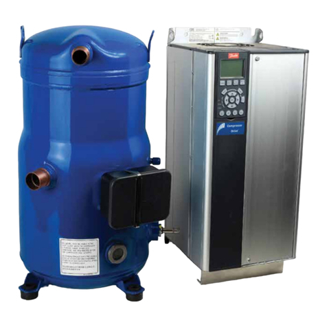
  9. Danfoss VZH052 Series User manual

Danfoss VZH052 Series User manual

This manual suits for next models

1

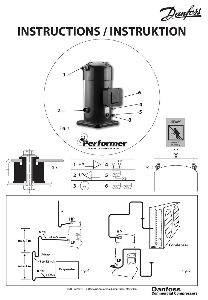
Other Danfoss Air Compressor manuals

Danfoss CXH User manual

Danfoss

Danfoss CXH User manual

Danfoss PSH Series User manual

Danfoss

Danfoss PSH Series User manual

Danfoss AKC 25H1 User manual

Danfoss

Danfoss AKC 25H1 User manual

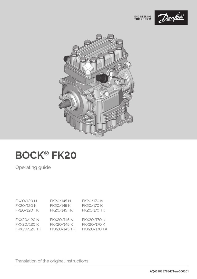
Danfoss BOCK FK50 User manual

Danfoss

Danfoss BOCK FK50 User manual

Danfoss BOCK HG66e User manual

Danfoss

Danfoss BOCK HG66e User manual

Danfoss BOCK FK20 User manual

Danfoss

Danfoss BOCK FK20 User manual

Danfoss VZH028 Instruction Manual

Danfoss

Danfoss VZH028 Instruction Manual

Danfoss MLZ116 User manual

Danfoss

Danfoss MLZ116 User manual

Danfoss VTT Series User guide

Danfoss

Danfoss VTT Series User guide

Danfoss VZH028 User manual

Danfoss

Danfoss VZH028 User manual

Danfoss VZH088-G single Instruction Manual

Danfoss

Danfoss VZH088-G single Instruction Manual

Danfoss DCJ Series User manual

Danfoss

Danfoss DCJ Series User manual

Danfoss MT User manual

Danfoss

Danfoss MT User manual

Danfoss Performer SH090 Instruction Manual

Danfoss

Danfoss Performer SH090 Instruction Manual

Danfoss Performer SM Series Instruction Manual

Danfoss

Danfoss Performer SM Series Instruction Manual

Danfoss Maneurop NTZ Series Instruction Manual

Danfoss

Danfoss Maneurop NTZ Series Instruction Manual

Danfoss VLZ065 Instruction Manual

Danfoss

Danfoss VLZ065 Instruction Manual

Danfoss Performer SH090 Instruction Manual

Danfoss

Danfoss Performer SH090 Instruction Manual

Danfoss H Series User manual

Danfoss

Danfoss H Series User manual

Danfoss MLZ Evolution A Instruction Manual

Danfoss

Danfoss MLZ Evolution A Instruction Manual

Danfoss MLZ Series User manual

Danfoss

Danfoss MLZ Series User manual

Danfoss Performer SH090 Instruction Manual

Danfoss

Danfoss Performer SH090 Instruction Manual

Danfoss VCH115 User guide

Danfoss

Danfoss VCH115 User guide

Danfoss DSF485A4ABA User manual

Danfoss

Danfoss DSF485A4ABA User manual

Popular Air Compressor manuals by other brands

Craftsman 919.724591 owner's manual

Craftsman

Craftsman 919.724591 owner's manual

Atlas Copco GA 30+ Instruction book

Atlas Copco

Atlas Copco GA 30+ Instruction book

Hitachi Highly WHP11500VSDPC9EQ installation manual

Hitachi

Hitachi Highly WHP11500VSDPC9EQ installation manual

Craftsman 919.167810 owner's manual

Craftsman

Craftsman 919.167810 owner's manual

Yamato 24/2 M1CD instruction manual

Yamato

Yamato 24/2 M1CD instruction manual

Clarke 2242117 Operation & maintenance instructions

Clarke

Clarke 2242117 Operation & maintenance instructions

Sparmax DC-25XR user manual

Sparmax

Sparmax DC-25XR user manual

Briggs & Stratton Air Compressor Operator's manual

Briggs & Stratton

Briggs & Stratton Air Compressor Operator's manual

Fini F3GST2TK Operator's manual

Fini

Fini F3GST2TK Operator's manual

Campbell Hausfeld RP3300 Easy setup guide

Campbell Hausfeld

Campbell Hausfeld RP3300 Easy setup guide

Ingersoll-Rand UP6 20 HP Option manual

Ingersoll-Rand

Ingersoll-Rand UP6 20 HP Option manual

Parkside PKO 270 A1 operating instructions

Parkside

Parkside PKO 270 A1 operating instructions

Clas Ohlson QIE-ZTH-15 manual

Clas Ohlson

Clas Ohlson QIE-ZTH-15 manual

Ferm CRM1046 Original instructions

Ferm

Ferm CRM1046 Original instructions

BE AC153 Operation manual

BE

BE AC153 Operation manual

RIDGID OF25150A Operator's manual

RIDGID

RIDGID OF25150A Operator's manual

Johnson Controls QUANTUM LX Setup

Johnson Controls

Johnson Controls QUANTUM LX Setup

Ring Automotive RAC700 instructions

Ring Automotive

Ring Automotive RAC700 instructions

manuals.online logo
manuals.online logoBrands
  • About & Mission
  • Contact us
  • Privacy Policy
  • Terms and Conditions

Copyright 2025 Manuals.Online. All Rights Reserved.

Danfoss scroll compressors
VZH052-065
Single
R410A
Application guidelines
http://cc.danfoss.com
Content
GENERAL INFORMATION........................ 4
PRODUCT INFORMATION ....................... 5
Features......................................................5
How do IDVs work?................................................... 5
Compressor model designation ..............6
Nomenclature ............................................................ 6
Technical specifications............................7
Dimensions ..............................................10
VZH052-065G/J/H ...................................................10
Electrical data, connections and wiring13
Supply voltage.........................................................13
Phase sequence and reverse rotation
protection.................................................................. 15
IP rating.......................................................................16
Motor protection.....................................................16
Approval and certificates .......................17
Low voltage directive 2014/35/EU.................... 17
Internal free volume............................................... 17
SYSTEM DESIGN..................................... 18
Drive installation.....................................18
Direct and indirect exposure of drive to water
18
Condensation...........................................................18
Dust Exposure..........................................................18
Mechanical Mounting ...........................................18
Ambient temperature ...........................................19
EMC installation ..................................... 20
EMC best practices .................................................20
EMC remediation ....................................................20
EMC remediation ....................................................21
Mechanical dimension .........................................21
Unit Architecture.................................... 22
Design piping ......................................... 23
General requirements...........................................23
Design compressor mounting .............. 24
General requirements...........................................24
Single requirements...............................................24
Manage oil in the circuit ........................ 25
Requirement.............................................................25
System evaluation ..................................................25
Test, criteria and solutions...................................25
Manage sound and vibration................ 26
Compressor sound radiation..............................26
Mechanical vibrations...........................................27
Gas pulsation............................................................27
Manage superheat ................................. 28
Requirement.............................................................28
System evaluation ..................................................28
Test, criteria and solutions...................................29
Manage off cycle migration................... 30
Requirement.............................................................30
System evaluation .................................................30
Manage operating envelope................. 32
Requirement.............................................................32
System evaluation ..................................................33
Manage speed limit.................................37
Speed limit requirement......................................37
Start/Stop/Ramp setting......................................37
Control logic ........................................... 38
Safety control logic requirements....................38
Short cycle protection .........................................39
Defrost cycle logic ..................................................39
Pump-down logic recommendations.............39
Oil management logic ..........................................40
Reduce moisture in the system..............41
Requirements........................................................... 41
Solutions.....................................................................41
INTEGRATION INTO SYSTEMS.............. 42
Assembly line procedure....................... 42
Compressor storage...............................................42
Compressor holding charge ...............................42
Handling ....................................................................42
Piping assembly.......................................................43
System pressure test and leak detection .......43
Vacuum evacuation and moisture removal .44
Refrigerant charging..............................................44
Dielectric strength and insulation resistance
tests..............................................................................44
Commissioning....................................... 45
Preliminary check....................................................45
Initial start-up...........................................................45
System monitoring.................................................45
Oil level checking and top-up............................45
Troubleshooting..................................... 46
Dismantal and disposal ......................... 49
ORDERING INFORMATION ................... 50
Packaging ............................................... 50
Ordering codes........................................51
Accessories...............................................52
3AB237586440343en-000601
PRODUCT INFORMATIONSYSTEM DESIGNINTEGRATION INTO SYSTEMORDERING INFORMATION GENERAL INFORMATION
General Information
Danfoss scroll compressors are designed and
manufactured according to the state of the
art and to valid European and US regulations.
Particular emphasis has been placed on
safety and reliability. Related instructions are
highlighted with the following icons:
This icon indicates instructions to avoid
safety risk.
This icon indicates instructions to avoid
reliability risk.
The purpose of this guideline is to help
customers qualify compressors in the unit.
You are strongly advise to follow these
instructions. For any deviation from the
guidelines, please contact Danfoss Technical
Support. In any case, Danfoss accepts no
liability as a result of the improper integration
of the compressor into the unit by the system
manufacturer.
R
4AB237586440343en-000601
GENERAL INFORMATIONSYSTEM DESIGNINTEGRATION INTO SYSTEMORDERING INFORMATION PRODUCT INFORMATION
Features
Danfoss Intermediate Discharge Valves (IDVs)
are located close to the discharge side of the
compressor. They reduce excessive compression
of refrigerant under part-load conditions while
maintaining the same cooling capacity. The IDVs
open when discharge pressure falls below the
built-in optimization point. They adapt the effort
of the motor to the varying load and pressure
conditions in the system, thus reducing the effort
of the motor and its electrical consumption
and improving the system’s seasonal energy
efficiency.
How do IDVs work?
Intermediate discharge
valves for better efficiency
at low pressure-ratio Optimized scrolls for
better part load efficiency
New distributed IPM
motor lead to higher
power factor
High speed oil circulation
minimized by a oil return
tube
Linear control oil pump
PVE 32 lubricant ensures better
lubrication and efficiency
New designed oil cup to
minimize oil stirring loss under
high liquid level
EMC (Electro-Magnetic
Compatibility) bracket
provided allows for
grounding termination
of shielded wire-harness,
which reduces EMC
emissions between drive
and compressor
5AB237586440343en-000601
GENERAL INFORMATIONSYSTEM DESIGNINTEGRATION INTO SYSTEMORDERING INFORMATION PRODUCT INFORMATION
Compressor model designation
Nomenclature
Note:
High overload output power: output power @160% Torque
Compressor nomenclature
Frequency converter
nomenclature
H2E20T4P11K303CDS
Dedicated compressor
drive for VZH scroll
Serie 303
High overload
output power
in kW
Main supply voltage
T2: 200-240V/3 ph/50-60 Hz
T4: 380-480V/3 ph/50-60 Hz
T6: 525-600V/3ph/50-60 Hz
RFI class
H2/H3/HX
Enclosure protection
IP rating
E20/E55
P11K/P15K/P22K
BNAGC065ZHV
Variable speed
Family
VZH scroll
Lubricant
PVE 32 (160 HV) lubricant,
R410A refrigerant
Swept volume
in cm³/rev
Evolution index
Motor protection type
N: no internal motor protection
(protection by drive)
Equipement version
A: brazed connections, single version
D: brazed connections, unified version
Motor voltage code to CDS303 *
G: 380-480V/3~/50 & 60Hz
H: 525-600V/3~/50 & 60Hz
J: 200-240V/3~/50 & 60Hz
* main supply voltage to frequency converter
Design pressure ratio
C: IDV and part load
ef iciency optimizedf
Single version Threaded None
Unified version Threaded Threaded
Oil sight glass Oil level switch
6AB237586440343en-000601
GENERAL INFORMATIONPRODUCT INFORMATIONSYSTEM DESIGNINTEGRATION INTO SYSTEMORDERING INFORMATION
Technical specifications
To have the optimum compressor selection,
select a compressor size which achieves the
peak load system cooling capacity demand at its
maximum speed.
Detailed performances can be found in
datasheets and in selection programs.
Compressor size
Different frequency converter variants are
available according to:
1. Mains supply voltage
2. IP class (CDS303 drives are available in IP20 or
IP55 housings)
3. RFI (Radio Frequency Interference) class H2/H3
or HX.
4. Printed Circuit Board (PCB) coated
When the compressor size and mains voltage
have been defined in the above selection criteria,
the code number tables from the“Ordering
information and packaging”section provides the
appropriate frequency converter sizes and up
to four corresponding code numbers for each
compressor model.
Note this compressor is equipped with
a six-pole electrical motor so the applied
frequency from the inverter will be 50 Hz for
1000 rpm up to 330 Hz for 6600 rpm.
Please refer to the table below
Frequency converter
variants
Compressor and
frequency converter
combinations
min max
Compressor speed rps 16.7 110
rpm 1000 6600
Drive output frequency Hz 50 330
PRODUCT INFORMATION
7AB237586440343en-000601
GENERAL INFORMATIONPRODUCT INFORMATIONSYSTEM DESIGNINTEGRATION INTO SYSTEMORDERING INFORMATION
Technical specifications
Compressor
specifications
Frequency converter
specifications
Compressor
model
Swept volume
Displacement
Oil charge Net weight
1000 rpm 3000 rpm 3600 rpm 6600 rpm
(cm³/rev) (cu.in/rev) (m³/h) (cu.ft/h) (m³/h) (cu.ft/h) (m³/h) (cu.ft/h) (m³/h) (cu.ft/h) (dm3)(oz) (kg) (lbs)
VZH065 65.1 4.0 3.9 138 11.7 413 14.1 498 25.8 911 1.57 53 35 77
VZH052 52.1 3.2 3.1 109 9.4 332 11. 3 399 20.6 727 1.57 53 35 77
Mains supply voltage
T2: 200 - 240 V ±10% (3-phase)
T4: 380 - 480 V ±10% (3-phase)
T6: 525 - 600V ±10% (3-phase)
Supply frequency 50 / 60 Hz
Output voltage 0 - 100 % of supply voltage
Inputs 6 digital (0-24V), 2 analog (0/±10V or 4-20mA, scalable)
Programmable outputs 2 digital (0-24V), 1 analog (0/4-20mA), 2 relay
Protection functions Over-current protection, low / high current handling
Compressor functions Motor protection, compressor ramp up/down control
PRODUCT INFORMATION
8AB237586440343en-000601
GENERAL INFORMATIONPRODUCT INFORMATIONSYSTEM DESIGNINTEGRATION INTO SYSTEMORDERING INFORMATION
Technical specifications
OIL level sensor A TEKLAB LC-XN optical-electrical level sensor
is fixed on the inverter compressor. The oil level
sensor prism is fixed on the compressor, the
electrical part is ordered by accessory kit. The oil
level sensor monitors the compressor oil level
and sends oil level signal to an external relay or
digital input of unit controller. A 5±2 seconds
delay is recommended to mitigate oil level
fluctuationand avoid false alarms.
- Lack of oil: Circuit between 2 and 3 will be
opened internally, there will be no current
flowing through load or coil of external relay,
relay is open.
- Enough oil: Circuit between 2 and 3 will be
closed internally, there will be current flowing
through load or coil of external relay, relay is
close.
Note: For 24VDC, output voltage in case of lack
of oil is >13V DC and not 0V
For customers who needs UL certificates, please
order 24V AC/DC sensor.
Oil level sensor is a special component which
assembles on variable speed compressor. It is
provided in oil level sensor accessory kit.
VZH052-065
1
L1
L2
L3
N
2
3
External
Load / Relay
230VAC MODEL
1
0VAC
24VAC
2
3
External
Load / Relay
24VAC MODEL
1
0VDC
24VDC
2
3
External
Load / Relay
24VDC MODEL
Sensor Sensor
Sensor
PRODUCT INFORMATION
9AB237586440343en-000601
GENERAL INFORMATIONPRODUCT INFORMATIONSYSTEM DESIGNINTEGRATION INTO SYSTEMORDERING INFORMATION
Dimensions
Version Compressor model D H H1 H2 L1 L2 Outline drawing number
(mm) (inch) (mm)(inch) (mm) (inch) (mm) (inch) (mm) (inch) (mm) (inch)
Single VZH052-065 183.5 7.22 436 17.17 403 15.87 261 10.28 190.5 7.5 190.5 7. 5 8590007
Unified VZH052-065 183.5 7.22 436 17.17 403 15.87 261 10.28 190.5 7.5 190.5 7. 5 8590013
VZH052-065G/J/H
H
H1
ΦD
H2
L2
L1
H
H1
ΦD
H2
L2
L1
Single version Unified version
EMC bracket to terminations
of shielded wire
Earth grounding
Mounting GrommetTerminal box
Ø 41
29.5
Recommended torque for
mounting bolts: 11 Nm (±1 Nm)
Ø11
PRODUCT INFORMATION
10 AB237586440343en-000601