Speedtech 68-74 X-Body User manual
Instructional Guide
Billet Aluminum Body Mounts
68-74 X-Body

Aluminum Body Mounts Page 2
Figure 1 1969 Nova, features our Body Mounts, Shane York
Congratulations on the purchase of your new Speedtech Performance Aluminum Body
Mounts. Use only approved and appropriately rated jack and jack stands, be sure to take
all safety precautions required to do the job safely and correctly. If you are unsure, seek
the assistance of a highly qualified workshop to assist you.
Read and understand all instructions thoroughly before you begin. For the most part, assembly
and set up of your new Aluminum Body Mounts can be done in a home garage with hand tools
and basic equipment.
We enjoy seeing the progress our customers are making as they work through their builds so join
the Team Speedtech group on Facebook and share your pictures and your story.
From everyone at Speedtech Performance we send you all best wishes for your project!

Aluminum Body Mounts Page 3
Installation Guide
TABLE OF CONTENTS
1. GENERAL INFORMATION
1.1 THIS GUIDE
1.2 OVERVIEW
1.3 TOOLS
2. CHECK IN PARTS AND HARDWARE
2.1 CHECKING IN THE ORDER
2.2 CHECK IN TABLES
3. GETTING STARTED/INSTALLATION
3.1 LEVELING AND SUPPORT
3.2RADIATOR SUPPORT
3.3SIDE LOCATIONS
3.4 REPEAT
4. FINISHING
4.1 TORQUE
5. CONGRATULATIONS

Aluminum Body Mounts Page 4
1.0 GENERAL INFORMATION
Back to Table to Contents
1.1 This Guide
Thank you for purchasing your new Speedtech Performance Aluminum Body Mounts. These instructions
outline the Aluminum Body Mounts that will be installed with the Speedtech Performance ExtReme or a
factory Subframe.
1.2 Tools
Installation of the Speedtech Performance Aluminum Body Mounts can be done on the floor
with simple hand tools.
Additional things to have before you start:
•Wrench
•Jack Stands
•Anti-Seize
•Post Lift (If possible)
2.0 CHECK IN PARTS AND HARDWARE
Back to Table to Contents
2.1 Checking in the Order
Best practice will be to check in your order as soonas possible afterreceiving the order. To check
in the order we have provided tables, these can be used as check lists for your order.
2.2 Check in Tables
X
#
Description
Size
2
Radiator Support Mounts (Upper and Lower Set)
1 Groove
2
Body Mount (Mid Position)
2 Groove - Larger
2
Rear Body Mount
2 Groove
2
Front Radiator Support –Bolt
1/2 x 3 NF
2
Mid Position - Bolt
5/8 x 4 NC
2
Rear Position –Bolt
5/8 x 3 ½ NC
2
Nylock Nuts
1/2
4
Washer –Flat
½
4
Washer –Flat
5/8
4
Washer –Lock
5/8
Note: There may be some extra hardware that was packaged that is not accounted for in the
check list. The hardware kits are made to fit multiple products and the excess is from that
process.

Aluminum Body Mounts Page 5
3.0 GETTING STARTED / INSTALLATION
Back to Table to Contents
3.1 LEVELING AND SUPPORT
The vehicle should be on a level surface before you start. Leave the vehicle on the ground
and remove all body mount bolts and lower bushing halves. Some bolts may be rusty, you may
need to apply penetrating fluid to remove them.
3.2 RADIATOR SUPPORT
Once the bolts are out there
should be enough room to slip
the top mount in the frame. With
the top mount in place, install
the interlocking lower mount.
Coat the threads of two 1/2 X 3”
bolts with anti-seize and loosely
thread into the body.
3.3SIDE
LOCATIONS
When there is enough room,
remove the old mounts and
slip the upper mounts in place. Coat the threads of your 7/16 X 3” bolts with anti-seize and
loosely thread through the lower bushings and into the body with a flat washer and lock washer
as shown in the diagram on page
Repeat for remaining bushing locations on that side.
3.4REPEAT
Repeat steps on the other side of the car.
4.0 FINISHING
Back to Table to Contents
4.1 TORQUE
As rubber mounts tend to compress and distort over time and all floor pans are slightly different,
ensure that the hood and fenders line up properly with the body, and that all bushings fully
contact the floor before torquing. Use additional shims (not included) to adjust as necessary.
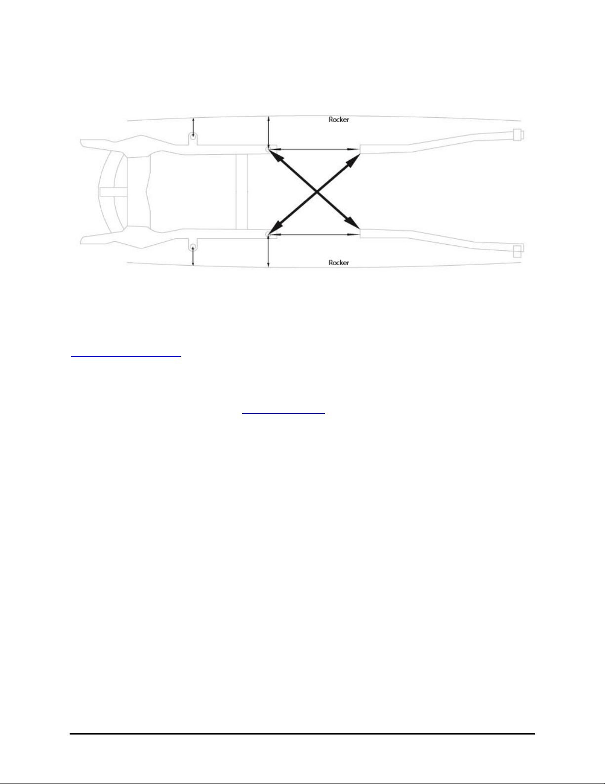
Cross measure the frame to ensure it is straight and square to the body. When the frame is
squared in, torque all bolts to 140 ft lbs.
NOTE: Recheck torque after approximately 100 miles of driving.
Aluminum Body Mounts Page 6
SEE MEASURING GUIDE TO ENSURE THE BODY/FRAME IS SQUARE
5.0 Congratulations
Back to Table to Contents
Congratulations on completing your project, we know you will get many years of enjoyment from
your project. Please join the group Team Speedtech on Facebook. Team Speedtech is a
community of like-minded individuals using Speedtech Performance products. The Group’s
members include customers, our dealers and factory employees - each with a passion for Pro
Touring muscle cars. You can ask questions and get advice from the group members as well
as share your experience. Within the group we enjoy seeing the videos and pictures during the
progress of your projects so post up. We also encourage you to share pictures and videos of
your finished projects out on the road, at the show & shine, on track or however you get
enjoyment from your ride, we want to see it!
Thank you for choosing Speedtech Performance! We know you have a choice, and we
appreciate that you entrust us with your chassis and suspension needs for you custom muscle
cars.
Speedtech Performance, LLC
4160 S. River Rd.
St George UT, 84770
(435) 628-4300
Table of contents
Other Speedtech Automobile Accessories manuals

Popular Automobile Accessories manuals by other brands


Wentronic
Wentronic goobay 44176 user manual

Abrams
Abrams EH-200 Installation and operation instruction

Code 3
Code 3 SuperVisor Installation & operation manual

Prorack
Prorack PR3501 installation instructions

Regency
Regency Digital-Display 2024 owner's manual

Directed
Directed Directechs DS3 installation guide