Abrams EH-200 Owner's manual

INSTALLATION AND OPERATION
INSTRUCTION
Expedition Series Remote Siren System
MODEL EH-200

INSTRUCTION OF OPERATION
This instruction is for the person who needs to understand how to operate the
Model EH-200 siren, PA amplifier. The intent of the instruction is to aid in
training the new operator and later to serve as a reference to the trained
operator.
GENERAL
Expedition Series siren EH-200, PA amplifier is designed to work with the
personnel of law enforcement, fire fight/rescue and EMS (Emergency Medical
Service) who is driving an emergency vehicle and requesting the right-of-way.
With easy of use, state-of-the-art and compact size of design, EH-200 will
contribute to minimize the detraction other than the traffic circumstance, help
to pass congested traffics effectively and reduce the time of installation.
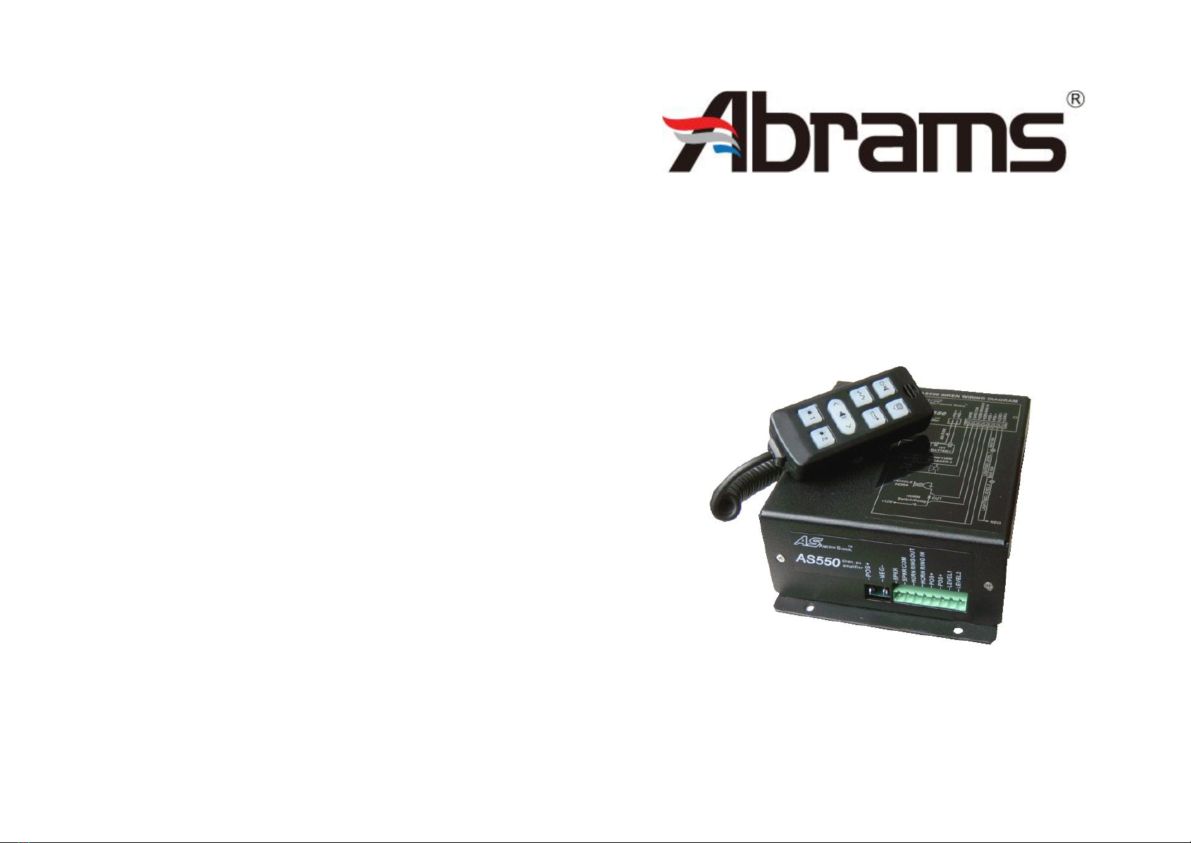
In addition, EH-200 amplifier is comprised of a PA (Public Address)
microphone in its handheld controller. The microphone push-to-talk button
overrides any siren signal for instant PA use. The siren is made up of an
amplifier and a remote controller. A current-sensing circuits built onto the
PCB eliminates the unexpected damage with speaker overload. The
HORN-TAP feature allows the driver to change the siren sound through the
vehicle’s horn ring switch without leaving hands out of the steering wheel.
With remotely mounted, handheld controller and microprocessor driven tone
generator, EH-200 provides a highly versatile electronic siren system.
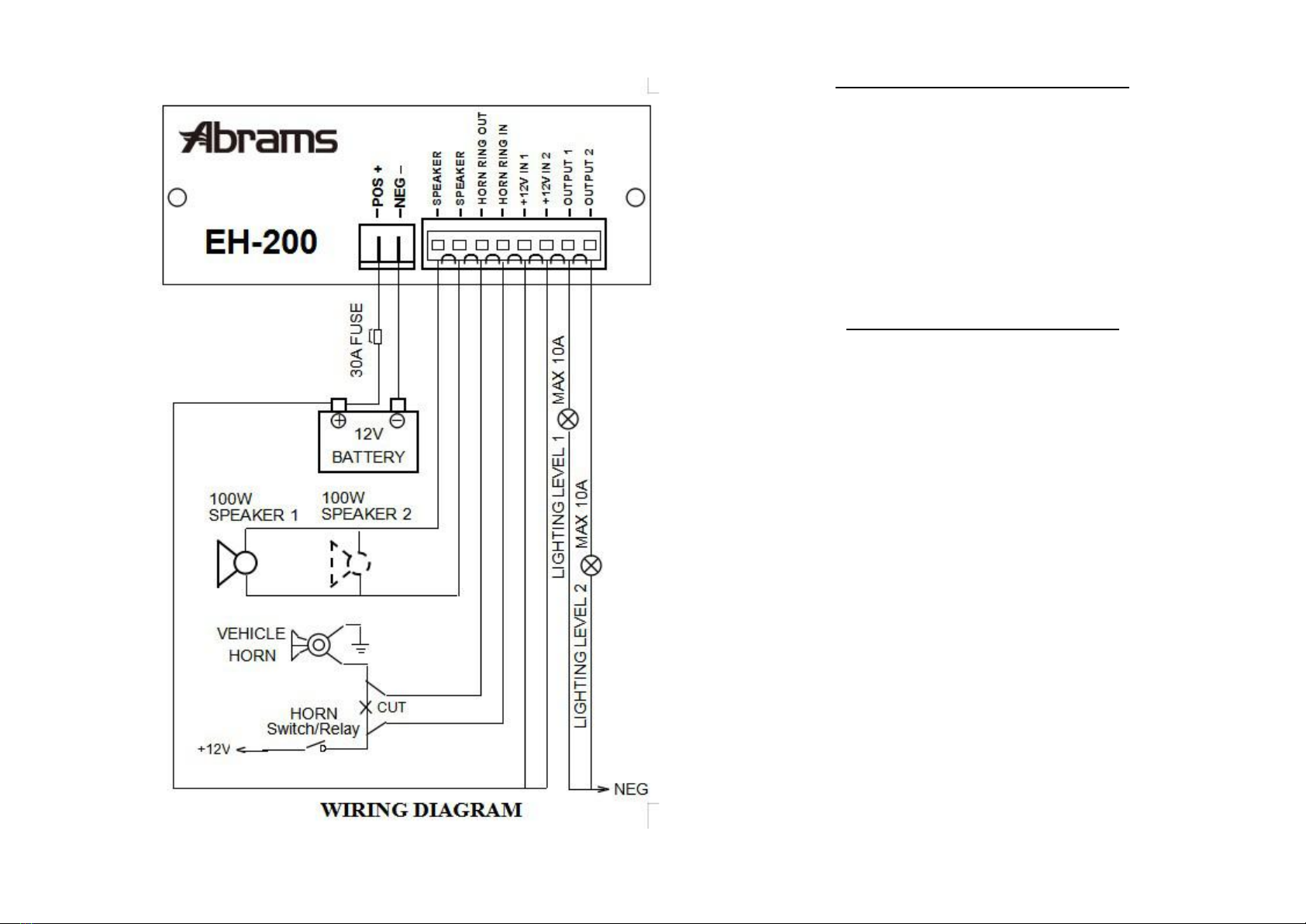
The EH-200 must be installed under the seat, in the truck or on the dash of
any vehicles with 12 volts, negative ground chassis system. Connection
between the handheld controller and the EH-200 amplifier box is via an
eight-conductor cable with RJ45 connectors at both ends for simple
installation.
The EH-200 can drive one or two 11-ohm impedance (100W) speakers. When
two speakers are used, which will generate total 200W output, they must
always be connected in parallel and in phase.
SPECIFICATIONS
◆Siren Section
Input Voltage……………10~16VDC (negative ground)
Input Current……………25 Amps @ 13.6VDC (dual 100W speakers)
Standby Current……………Less than 160 mA
Output Voltage……….Maximum 200W @ 12VDC (dual 100W speakers)
Operating Temperature……………-30℃to +65℃
Dimensions (HWD):
Handheld controller……………1.0"×1.6"×3.7"
Amplifier……………2.6″×5.4″×7.0″
Net weight……………Approximately 3.44 lbs
◆Lighting Section
Warning Light Control……………2 levels
OUTPUT 1……………10A maximum
OUTPUT 2……………10A maximum

OVERVIEW
WARNING
Failure to follow the safety precautions below may result in property damage,
serious injury, or death to you, to passengers, or to others.
SOUND HAZARDS –Your hearing and others’, in or close to your
vehicle with EH-200 equipped, could be damaged by the loud sound. This can
occur from exposures to loud siren/PA sounds. All sounds generated by
EH-200 may, in certain situations, cause permanent hearing loss. You should
minimize your exposure times and wearing proper hearing protection, for
hearing conservation guidance, refer to federal, state or local
recommendations.
DETRACTION WARNING –If the unique combination of
emergency vehicle equipments installed in your vehicle has resulted in the
siren controls being installed in the position that requires the eyes of the driver
detracted from the traffics, operate controls only while your vehicle is stopped.
It is necessary to watch the traffics while in driving and recommended to
control EH-200 by touch only.
SOUND EFFICIENCY WARNING –It may not alert everyone
although EH-200 is operating properly in your vehicle. People may not hear
the siren sound so you MUST continue driving cautiously. Frequently inspect
the speaker to ensure that it is clear of any obstruction, such as snow or mud.
Improper use of the speaker or of its installation will reduce the efficiency of
sound output, which results in degrading the alert effectiveness. Be also aware
that the use of EH-200 does not give you the right to force your way through
traffic. Your siren sound, the action is requesting the right-of-way only.
EH-200 is made up of two separated electronic devices with a cable
connected between them. The amplifier box contains all intelligence to
generate siren sound and PA amplification.
A current-sensing circuit protecting the amplifier from overload is built in.
Upon a short circuit/overload such as overheat inside the speaker, or improper
vibration of speaker diaphragm, is sensed, the amplifier will be disabled to
minimize possible damage of the amplifier. A regular fuse of 20 amperes is
also installed inside the amplifier to protect the siren system.
When the vehicle horn ring switch is operated, depending on the selection of
the externally accessible three-pin jumper’s position, the siren will produce
either Air Horn or Manual siren sound. With the power of the siren turned off,
the horn ring switch closure will perform the regular vehicle horn sound.

OPERATION
HANDHELD CONTROLLER
All controls utilized during normal operation of the EH-200 are located on the
handheld controller.
1. Microphone – The microphone for talk.
2. ON/OFF –Power on/off and standby. It provokes the power of the siren
system. By depressing this button, the backlights are lit in blue, and the power
of the siren is turned on, press and hold it for two seconds, the power is turned
off. This button can also bring the siren into standby mode. While depressing
this button all of function will be stopped instantly to standby.
3. PTT (Push To Talk) – Press and hold this button will mute all siren sound
and instantly enable PA function. Releasing this button will revert the tone
back to what EH-200 was sounding. You may Change the PTT volume by
adjusting the "PTT gain" trimmer on back of siren amplifier.
4. Manual –The momentary button. With no siren sound, depressing this
button once provoked "Peak and Hold" sound. "Coast Down" sound is
spawned as this switch is released.
5. AIR –The momentary button. With no siren sound, depressing this
button once creates "Air Horn" sound. The sound ceases as soon as the button
is released.
6. Tone selecting –siren tone selecting button, depressing this button’s right
once, it will scroll through different sirens tones, they are: Yelp, Hi-Lo,
Hyper-Lo, Hyper-Yelp, Whoop, Wail, standby, depressing this button’s left
once, it will scroll through reverse different sirens tones, they are: Wail, Yelp,
Hi-Lo, Hyper-Lo, Hyper-Yelp, Whoop, standby.
7-8. Lighting Control –the buttons for the light control, depress the
relevant button, the relevant indicator light will be lighted, it indicates the
light is working on.
On the standby mode, the siren will be powered off after 70 minutes.
1.Microphone
2.Power On/Off
3.Push To Talk
4.Manual
5.Air Horn
6.Tone selecting
7-8.Lighting Control
1
2
3
4
5
6
7
8

HORN-TAP FEATURE
The HORN-TAP feature allows the driver to enable and change the audible
siren sound via the vehicle’s horn ring. The horn ring switch will emulate the
function of the "AIR" button on the handheld controller. To use HORN-TAP
feature, the HORN RING IN and HORN RING OUT on the amplifier box
should connect to the vehicle’s horn ring switch. See figure and Installation
section, Electrical Installation g. 2 for instructions of wiring on HORN RIGH
IN and HORN RING OUT.
FOOTSWITCH/PURSUIT FEATURE
A footswitch may be substituted for the "HORN-TAP" feature. It may be
required under some circumstances, such as in the event of pursuit. See the
Installation section Electrical Installation g. 2 for more information if a
footswitch is required.
INSTALLATION
A. Unpacking – After unpacking the Model EH-200, examine it for damage
that may have occurred during transit. File a claim immediately with the
carrier stating the extent of the damage if the EH-200 has been damaged.
Carefully check all enveloped, shipping labels and tags before removing
or destroying them.
B. Amplifier Installation
a. The EH-200 amplifier is not waterproof. It must be mounted in
a location that is sheltered from rain, snow, standing water, etc.
It must be also installed in an adequately ventilated area. Do
not install near heater ducts or under the vehicle’s hood.
b. Some possible mounting locations are: in the trunk, under the
rear deck, under the front seat or in the equipment cabinet.
Keep in mind that the control cable is 3 meter (9.8 feet) long.
c. Using the mounting holes on the amplifier as a template, scribe
four drill position marks at the mounting locations. Be sure that
both sides of the mounting surface are clear of parts that may
be damaged.
d. The siren accessory kit with mounting hardware supplied
provides the siren user with a choice of mounting hardware.
Secure the EH-200 amplifier to the mounting surface, using the
mounting hardware, including lockwashers.

C. Handheld Controller Installation
a. Although the handheld controller can be laid on any place in
the cab, it sometimes needs to be fastened in a certain place.
The installer then should ensure that the equipment is installed
only in the areas recommended by the vehicle manufacturer.
Failure to observe this warning will reduce the effectiveness of
some safety equipments, such as the air bag, or damage the air
bag, causing serious injury or death to you or others.
b. The location selected to mount the handheld controller and its
holder must not impair the driver’s ability to safely drive the
vehicle as he/she operates the siren. The selected location
should afford good visibility and free accessibility to the
handheld controller.
D. Electrical Installation
a. Be caution that any hot wire (+12V) shorts to vehicle frame,
high current conductors can cause hazardous sparks resulting in
electrical fires or molten metal. It is recommended that
disconnect the cable on the negative end of the battery before
performing installation.
b. Do not connect the EH-200 system to vehicle battery until all
other electrical connections are made and mounting of all
components is complete. Verify the polarities of the cable once
again and ensure that no short circuits exist, before connecting to
the battery terminals.
c. Install the supplied 8-conductor, RJ45 cable between the siren
and the handheld controller. Install one end of the cable to the
mating connector on the handheld controller and install the
other end into the mating connector on the amplifier box.
d. If routing the cable requires drilling a hole in sheet metal or
other material, drill a 5/8″hole in the material. Install a 5/8″
grommet (not supplied) or similar protective devices in the
hole, to protect the cable from damage which sharp edges
could cause.
e. User-supplied 14-gauge red and black wires are required for
positive (+) and negative (-) connections. User-supplied
18-gauge wires are required for the speaker, horn ring out and
horn ring in connections. User-supplied two 14-gauge red
wires are required for positive (+) in connections.
f. To install the positive and negative power wires, strip 1/4″of
insulation from the end of the wires. Then insert the wire into
the quick-on connector (supplied) and cramp securely with
proper tool. Connect the red wire to "POS+" position and black
wire to the "NEG-" position of the connectors on EH-200.
Connect the other ends of the wires directly to the terminals of
the vehicle battery after all installation is complete.
g. The unit is supplied in the accessory kit with a eight-position,
pluggable connector to accommodate the other electrical
installation. Insert the wire into the green pluggable connector
and tighten the screw at the appropriate connector position.
1. Speaker -- EH-200 is designed to operate with one 11-ohm
impedance (100W) speaker or two 11-ohm impedance (100W)

speakers. Speakers are not included as part of the siren. Any
11-ohm 100W speakers for use with emergency vehicle may be
considered to use. When using two 100W speakers, they must be
connected in parallel and in phase. For instance, the pin 1 of the
speaker A should combine the pin 1 of the speaker B to the
"SPEAKER" position of the connector. The other two leads should
connect to the other "SPEAKER" position of the connector.
2. Horn Ring In and Out – The horn ring transfer circuits of the
siren is capable of switching a maximum of 10 amperes. An
external relay is not required for horn ring operation. Locate the
wire that connects the vehicle horn ring switch to the horn or horn
relay. Cut this wire. Connect a wire from "HORN RING IN"
position on the connector to the horn ring side of the wire that was
just cut. Connect a wire from "HORN RING OUT" position on the
connector to the horn side of the cut wire. Properly insulate the
wires. (Note: A footswitch may be substituted to use with
"HORN-TAP" function. Connect a wire to one end of the
footswitch wire to the other end of the footswitch wires and the
vehicle chassis.)
3. Lightbar Control power – To install the lightbar positive power
wires, strip 1/4″of insulation from the end of the 14-gauge wires.
Then connect the wire to "POS+" position of the connectors on
EH-200. Connect the other ends of the wires directly to the
positive terminal of the vehicle battery.
4. Lightbar Control –To install the lights control wires, strip
approximately 1/4″of insulation from the end of the lights wires.
Connect lights to "OUTPUT 1" that you wish to activate No.7
button on handheld controller. Connect lights to "OUTPUT 2" that
you wish to activate No.8 button on handheld controller.
h. Plug the eight-position connector into the mating connector on
the unit, and apply pressure until it locks into place.
i. Ensure that there are no loose wire strands or other bare wire
that may cause a short circuit. All wires must be protected from
any sharp edged that could eventually cut through the insulation.
Also use an ohmmeter to verify that a short circuit does not
exist between the positive (+) leads and the vehicles chassis.
j. Perform visual check of all connections and wiring once more
before connecting the red wire to the positive (+) terminal and
black wire to the negative (-) terminal of the battery.
k. EH-200 provides an auxiliary +12V output, rated 1 amp
maximum. Whenever the siren amplifier is enabled, there will
be a +12V, 1 amp output available to drive an auxiliary output,
such as a high power relay or solenoid. The high power relay
then can turn warning lights on when the siren is activated.
Pressing microphone switch will also activate this output for
approximate 3 seconds. This feature is supplied by simply
connecting the red wire inside the siren box to the coil of a
+12V relay or solenoid. It will then control the auxiliary device
when the amplifier is energized.

TESTING AFTER INSTALLATION
After installation, test all the functions of Expedition Series siren EH-200
including the horn operation or footswitch if used, to ensure that it is
operating properly. All effective sirens and horns produce loud sounds (120
dB) that may cause permanent hearing loss. Always minimize your exposure
to siren sound and wear hearing protection. After installation and testing is
complete. Provide a copy of this manual to all operating personnel.
SERVICE AND MAINTENANCE
To properly service an electronic siren, you must have a good understanding
of automotive electrical systems and emergency signaling procedures.
Most of the components and electronic parts used in the model EH-200 are
standard items that can be obtained from any electronics supply shop. To
reduce equipment down-time, the factory recommends that the entire
amplifier’s printed circuit board (part No. 2500055A with microprocessor,
2500055A-01 without microprocessor) be replaced. The handheld controller
board is 2500056A. The printed circuit board is relatively inexpensive
allowing you to keep an adequate supply in your repair shop.
If the board without microprocessor is ordered, the original microprocessor
may be reused. The microprocessor can be removed from the defective board
and insert onto the new board. It is about 80% of failure due to other problems
than the microprocessor.
Contact your local agency for warranty service request.
The factory can and will service your equipment or assist you with technical

problems, should any arise, and that cannot be handled satisfactorily and
promptly locally. Suggest any communication should be tried and conducted
locally with agents before further attempts to the factory. If any unit is
returned for adjustment or repair, it can be accepted only if letter or phone in
advance of its arrival notified us. Such notice should clearly indicate the
service requested and give all pertinent information regarding the nature of
malfunction and, if possible, its cause.
REPLACEMENT OF OUTPUT TRANSISTORS
Failure of one or both of the output transistors is usually the result of a
defective speaker (short circuited voice coil). The factory recommends that
both output transistors be replaced should only one device prove to be
defective. Insure that the Sil-Pad insulators are installed between the heat sink
and transistors when installing new output transistors.
Make certain that the speaker(s) is (are) not defective before reinstalling the
repaired EH-200. After servicing is complete, perform a test of all functions to
ensure siren is operating properly. Whenever the siren is tested, be aware of
sound hazard. See the warning section above in the manual.
Table of contents
Other Abrams Automobile Accessories manuals