Speedtech 64-67 User manual

Instructional Guide
Chicane Coilover Bracket
64-72 A-Body

Chicane Coilover Brackets Page 2
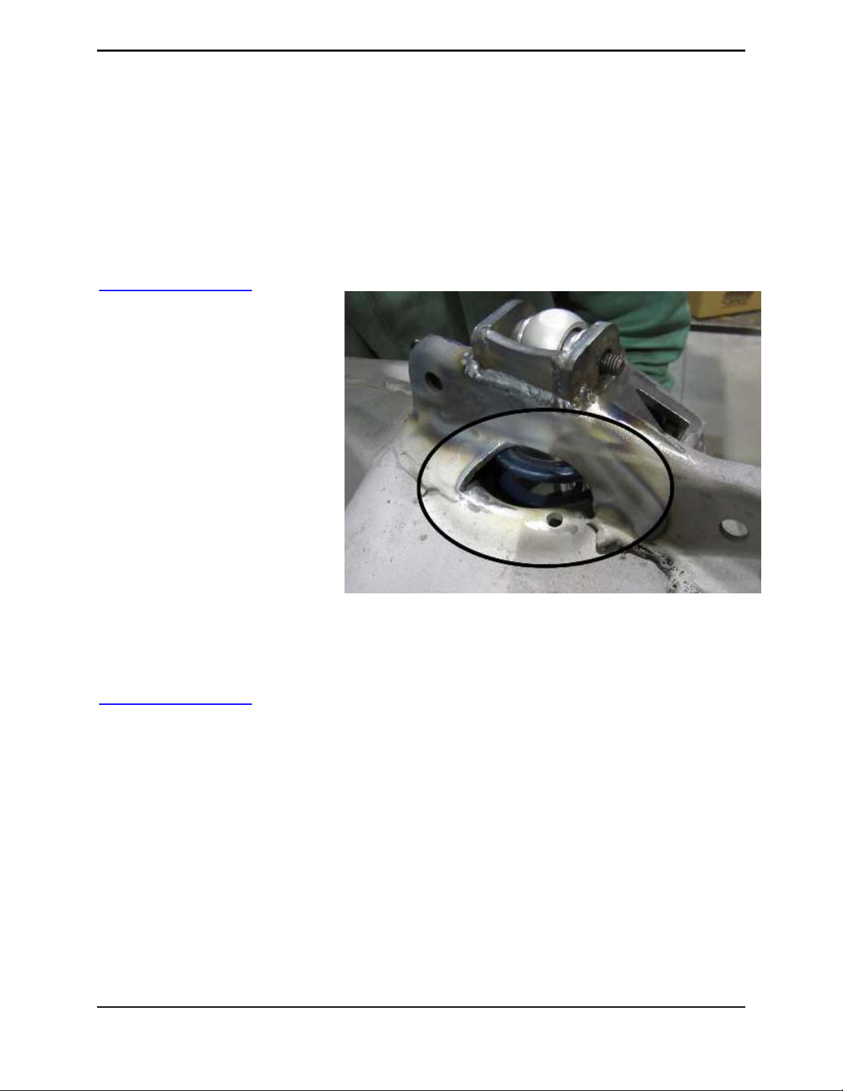
Figure 1 1970 Chevelle, features our Chicane Conversion Brackets –Alan Miller
Congratulations on the purchase of your new Speedtech Performance Chicane Coilover Brackets.
Installing this system will require the removal of your old suspension from the car. Use only
approved and appropriately rated jack and jack stands, be sure to take all safety precautions
required to do the job safely and correctly. If you are unsure seek the assistance of a highly
qualified workshop to assist you.
Read and understand all instructions thoroughly before you begin. For the most part, assembly
and set up of your new suspension can be done in a home garage with hand tools and basic
welding equipment. As your final step, review each assembly step again to be sure all fasteners
are correctly secured and torqued to specification.
We enjoy seeing the progress our customers are making as they work through their builds so join
the Team Speedtech group on Facebook and share your pictures and your story.
From everyone at Speedtech Performance we send you all best wishes for your project!

Chicane Coilover Brackets Page 3
Installation Guide
TABLE OF CONTENTS
1. GENERAL INFORMATION
1.1 THIS GUIDE
1.2 OVERVIEW
1.3 TOOLS
2. CHECK IN PARTS AND HARDWARE
2.1 CHECKING IN THE ORDER
2.2 CHECK IN TABLES
3. GETTING STARTED
3.1 DISCONNECT BATTERY
3.2 LEVELING AND SUPPORT
4. FACTORY DISASSEMBLY
4.1SUSPENSION REMOVAL
5. CUTTING
5.1 UPPER SHOCK MOUNT
5.2 INNER SPRING CUP
6. COILOVER ASSEMBLY
7. MOCK UP
7.1 NOTCH
7.2 FITTING
7.3 LOWER
7.4 UPPER
8. WELDING/INSTALLATION
8.1 FINAL WELDING
8.2 COATING
8.3 SUSPENSION
9. ALIGNMENT/TORQUE
9.1 TORQUE
9.2 ALIGNMENT
10. CONGRATULATIONS
10.1 WRAP UP

Chicane Coilover Brackets Page 4
1.0 GENERAL INFORMATION
Back to Table to Contents
1.1 This Guide
The following instructions are intended for professional installers and are guidelines only.
Speedtech Performance assumes no responsibility for the installation of any of its products
installed by others. All products are intended to be installed by qualified professionals.
NOTE! Some Items pictured may look different then the parts you have in the kit you received.
For example, in this guide we have only used pictures of the Chicane Coilover Brackets for the
early Camaro. Your application may have a slightly different shape the part is functionally the
same and is installed in the same manner described.
1.2 Overview
These instructions outline the Chicane Coilover Brackets. The system has been designed to work
with a factory subframe or chassis. Some photos in the install process may vary slightly from your
exact application.
WARNING! Once assembled you will need a professional wheel alignment performed. Driving a
vehicle without a proper alignment can be dangerous, towing is recommended to transport the
car prior to the alignment being performed.
While Speedtech's Chicane Coilover Brackets work great as an upgrade for your factory
suspension, it is also designed to meet the needs of those intending participate in off highway
road racing and autocross competition. To achieve maximum benefit from our system you should
anticipate adjusting and tuning of the suspension to achieve optimum performance specific to the
vehicle, driver and type of racing. Some of this, such as tuning sway bars and shock settings, can
be done track side through making adjustments and seeing/feeling how the car reacts to these
changes. We recommend a tire probe pyrometer and good quality air pressure gauge be in your
track side tuning kit.
1.3 Tools
Installation of the Speedtech Performance Chicane Coilover Brackets can be done on the floor
with simple hand tool, cut off wheel and a basic welder.
Additional things to have before you start:
•Silicon Based Grease
•Anti-Seize
•Wrench Set
•Torque Wrench
•Floor Stands
•Floor Jack
•Plasma Cutter (if possible)

Chicane Coilover Brackets Page 5
2.0 CHECK IN PARTS AND HARDWARE
Back to Table to Contents
2.1 Checking in the Order
Best practice will be to check in your order as soon as possible after receiving the order. To check
in the order we have provided tables, these can be used as check lists for your order. If you
discover anything missing form your order, call your authorized dealer as soon as possible.
2.2 Check in Tables
Upper Control Arms
X
#
Description
Size
1
Drivers Side Chicane Coilover Bracket
Depends on Vehicle
1
Passenger Side Chicane Coilover Bracket
Depends on Vehicle
2
Upper Shock Mount Shoulder Bolt
½”x 1 ¾”
2
Nylock Nuts
3/8”NC
3.0 Getting Started
Back to Table to Contents
3.1 DISCONNECT BATTERY
Because you will be cutting and welding, before any removal begins, disconnect the battery.
3.2 Leveling and Support
The vehicle should be on a level surface before you start. Jack up and properly support the
vehicle's frame. Remove the front wheels. For cars with drop off style rotors, reinstall one lug nut
if needed to prevent the rotor from falling off.
4.0 FACTORY DISASSEMBLY
Back to Table to Contents
4.1 SUSPENSION REMOVAL
Remove upper control arms, coil springs and shocks. Spindle removal is optional as well.
5.0 CUTTING
Back to Table to Contents

Chicane Coilover Brackets Page 6
5.1 UPPER SHOCK MOUNT
Remove the existing Upper Shock mount by cutting along the factory weld (arrows).
DO NOT CUT OFF THE UPPER CONTROL ARM MOUNT!
5.2 INNER SPRING CUP
After the shock mount is removed,
you will need to remove the inner
spring cup and clearance the hole
to about 4 ½” in diameter. This is
best done with a plasma cutter or
oxyacetylene torch. Clean up the
rough edges as needed.


Chicane Coilover Brackets Page 8
64-67 A-Body
Note: Notch on the
one side indicates the
front.
68-72 A-Body
Note: Driver side
chicane has part
number etching
on this top side.

Chicane Coilover Brackets Page 9
7.0 MOCK UP
Back to Table to Contents
7.1 NOTCH
Mark the width of the shock bolt area
of the bracket on the upper control
arm mount. Using these marks as a
guide, cut out a notch so that the
shock bracket butts up flush against
the side of the control arm mount.
Below is what you should end up
with.
7.2 FITTING
The end result for all years should
have the bracket sitting flush
against the upper control arm
mount. Note: because of
differences in years and factory
tolerances, some slight trimming of
the bracket may be required to
custom fit it to your specific frame.
Do not proceed to welding at this
time.
7.3 LOWER
Do not skip this step. Mock up the
lower control arm and coilover shock
assembly to make sure the upper
Chicane mount is located in the
correct location. This also ensures
that all shock components clear the
frame. To allow you to work with both
hands and keep everything in place,
support the lower control arm and
shock assembly.
Chicane Coilover Brackets Page 10
7.4 UPPER
Assemble the Chicane Bracket to the shock top eyelet. Visually center the shock and measure
the clearance from the outside of the spring to the frame. Optimal clearance is 3/8” to 1/2”.
If needed, remove the shock/spring assembly and trim the hole. Align the bracket into position so
that the shock is centered in the hole and will travel without hitting the frame. When you are sure
everything is aligned properly, TACK weld the upper Chicane mount in this location.
8.0 WELDING / INSTALLATION
Back to Table to Contents
8.1 FINAL WELDING
Now that you have double
checked everything and there is
no bind and no clearance issues,
you can do the final weld of the
Chicane upper bracket.
8.2 COATING
Once all welding is completed you
can paint or powder coat your
subframe/chassis.
8.3 SUSPENSION
Reassemble and install all suspension components.
9.0 ALIGNMENT / TORQUING
Back to Table to Contents
9.1 TORQUE
•Lower control arm nuts 40 ft/lbs
•Upper control arm nuts 50 ft/lbs
•Upper shock mount 30 ft/lbs
•Lower T bar mounting nuts 40 ft/lbs
9.2 ALIGNMENT
Be sure to double check all the fasteners! Set the car to the approximate ride height by adjusting
the shock lower spring nuts. This should be done before aligning the car. When finished, take
the vehicle to a competent professional alignment shop to have an alignment performed.

Chicane Coilover Brackets Page 11
Note: Use alignment specifications below, not alignment shop pre-programmed factory
specs!
These specs are only suggestions and may need additional changes to achieve the optimum
settings for your driving style or situation.
See specifications below.
Daily Driving, Street Performance Specifications
Driver Side
Passenger Side
4 Degrees positive Caster
4 ½ Degrees positive Caster
0 to ½ Degree negative Camber
0 to ½ Degree negative Camber
3/ 32 Total Toe-in
3/ 32 Total Toe-in
Aggressive Track Alignment Specifications
Driver Side
Passenger Side
5 ½ Degrees positive Caster
6 Degrees positive Caster
½ to 1 Degree negative Camber
½ to 1 Degree negative Camber
3/ 32 Total Toe-in
3/ 32 Total Toe-in
Original Alignment Specifications
**For reference purposes only. Do Not use these specs.
Driver Side
Passenger Side
½ Degree positive Caster
½ Degree positive Caster
¼ to ½ Degree negative Camber
¼ to ½ Degree negative Camber
1/8 Total Toe-in
1/8 Total Toe-in

Chicane Coilover Brackets Page 12
10.0 Congratulations
Back to Table to Contents
Congratulations on completing your project, we know you will get many years of enjoyment from
your project. Please join the group Team Speedtech on Facebook. Team Speedtech is a
community of like-minded individuals using Speedtech Performance products. The Group’s
members include customers, our dealers and factory employees - each with a passion for Pro
Touring muscle cars. You can ask questions and get advice from the group members as well
as share your experience. Within the group we enjoy seeing the videos and pictures during the
progress of your projects so post up. We also encourage you to share pictures and videos of
your finished projects out on the road, at the show & shine, on track or however you get
enjoyment from your ride, we want to see it!
Thank you for choosing Speedtech Performance! We know you have a choice, and we
appreciate that you entrust us with your chassis and suspension needs for you custom muscle
cars.
Speedtech Performance, LLC
4160 S. River Rd.
St George UT, 84770
(435) 628-4300
This manual suits for next models
1
Table of contents
Other Speedtech Automobile Accessories manuals


