Spekon 4 Series User manual
SPEKON GmbH
Owner’s Manual
Issue 9
Emergency Parachute January 2019
RE-5L
QD 200/0000-003-020 09/09
Owner’s Manual
RE-5L Emergency Parachute
Series 4, Part No. 50-216/06:00
Series 5, Part No. 50-216/07:00
© SPEKON Sächsische Spezialkonfektion GmbH Tel: ++49 (0)3586 456-0
Nordstraße 40 Fax: ++49 (0)3586 456-167
GERMANY http:// www.spekon.com

SPEKON GmbH
Owner’s Manual
Issue 9
Emergency Parachute January 2019
RE-5L
QD 200/0000-003-020 07/09 Page 2 of 26
Warning
No responsibility will be accepted by the manufacturer
for improper functioning of the emergency parachute if
-it is used without the previous approval of the
manufacturer outside the conditions and operating
limitations set in this manual;
-the instructions for packing and pre-flight
procedures, the general instructions as well as the
inspection cycle term have been failed to follow and
keep.

SPEKON GmbH
Owner’s Manual
Issue 9
Emergency Parachute January 2019
RE-5L
QD 200/0000-003-020 07/09 Page 3 of 26
Table of Contents Page
1 Technical Description 4
1.1 Intended Use 4
1.2 Technical Specifications 4
1.3 Scope of Supply and Parts List 5
1.4 System Function 6
1.5 Description of the Parachute 6
1.5.1 Canopy with Suspension Lines 6
1.5.2 Pilot Chute 6
1.5.3 Container 7
1.5.4 Harness 7
1.5.5 Locking Device 8
2 Instructions for Packing and Pre-Flight Procedures 8
2.1 Packing Tools 8
2.2 Inspection 8
2.3 Packing Instructions 9
2.3.1 Pre-Packing Procedures 9
2.3.2 Flaking, Pleating and Folding the Canopy 9
2.3.3 Riser Placement 11
2.3.4 Stowing of Suspension Lines 11
2.3.5 Placing Canopy in Container 11
2.3.6 Placing Pilot Chute and Closing Container 12
2.3.7 Completion 13
2.4 Putting on and Fitting of the Harness 13
3 General Instructions 14
3.1 Parachute Steering 14
3.2 Landing 14
3.3 Storage and Maintenance 14
3.3.1 Storage 14
3.3.2 Maintenance 14
4 Maintenance and Repair 15
4.1 Inspection Cycle 15
4.2 Scope of Inspection 15
4.2.1 Canopy with Suspension Lines 15
4.2.2 Pilot Chute 15
4.2.3 Container and Harness 16
4.2.4 Locking Device 16
4.2.5 Miscellaneous 16
4.2.6 Repair 16
5 Figure Section 17

SPEKON GmbH
Owner’s Manual
Issue 9
Emergency Parachute January 2019
RE-5L
QD 200/0000-003-020 07/09 Page 4 of 26
1. Technical Description
1.1 Intended Use
The RE-5L parachute is a personnel parachute. It is an emergency parachute assembly
which can be used by glider and airplane pilots as well as balloonists. Furthermore it can
be employed by aircraft control and escort personnel.
1.2 Technical Specifications
The RE-5L is a back parachute.
Alternatively, it can either be activated manually by pulling the ripcord or automatically by
pulling the static line.
If desired, the RE-5L will be equipped with a manual opening option only. In this case, the
parachute will be delivered without the static line and the notes described in the parachute
manual about how the parachute opens automatically do not apply.
The RE-5L emergency parachute meets the minimum standards set in TSO/JTSO-C 23d.
Technical Data
Maximum Deployment Speed for Maximum Operation Weight:
a) 327 km/h (176 kts/203 mph) for 115 kg (254 lbs)
b) 278 km/h (150 kts/172 mph) for 122 kg (270 lbs)
Minimum Bail Out Altitude for Horizontal Flight and Immediate Activation:
a) for v = 60 - 110 km/h: 80 m
b) for v = 110 - 327 km/h: 60 m
Minimum Opening Altitude for Vertical Fall:
for v = 0 - 220 km/h: 125 m
Repack Cycle: 360 Days
Service Life: 20 Years
Temperature Range: -40°C to +94°C (-40°F to 201°F )
Canopy Area: 41.5 m²
Number of Gores and Suspension Lines: 24
Dimensions of the Packed Parachute:
Series 4 840x380x65 mm
Series 5 550x380x90 mm
Weight of the Packed Parachute:
Series 4 7.5 kg
Series 5 7.2 kg
Force Needed to Open Locking Device: 7-15 daN
Turn Speed: ca. 30 Degrees/s
Forward Speed: 1-2 m/s
Rate of Descent Near the Ground:
for 77 kg Operation Weight 6.1 m/s
for 122 kg Operation Weight 7.3 m/s

SPEKON GmbH
Owner’s Manual
Issue 9
Emergency Parachute January 2019
RE-5L
QD 200/0000-003-020 07/09 Page 5 of 26
Important
The manual is to impart important information to the certificated senior or master rigger
concerning the right maintenance of the RE-5L parachute assembly. It should also provide
the pilot with important information about operation and how to maintain operational
readiness. Reading this manual does not replace the training of maintenance and inspec-
tion personnel. It should not enable the owner to pack the emergency parachute on his
own without training.
Any activities listed in this manual can only be performed by persons especially
trained or certificated for this purpose. Serious accidents may occur if you do not
follow the manual or deviate from its instructions.
If any questions arise please do not hesitate to contact the manufacturer. We will be
pleased to give you expert information.
Any parachutes delivered by us are produced and checked in accordance with the com-
pany’s quality management system.
Each parachute has an authorized release certificate (EASA Form One).
1.3 Scope of Supply and Schedule of Part Numbers
Component Part Part No. Comments
Canopy 50-186/10:00
Pilot Chute 50-144/16:00
Container
Series 4 50-290/11:00
Series 5 50-290/10:00
Harness
Series 4 50-291/06:00
Series 5 50-291/07:00
Locking Device
Static Line 50-12/01:00 on Customer’s Request
Ripcord 500-50-136
or 500-50-76
Carrying Bag 50-138/08:00 on Customer’s Request
Man./Auto. Locking Loop (2x) 50-164/02:00 Spare Part
Man. Locking Loop 50-164/03:00 Spare Part
Log Book

SPEKON GmbH
Owner’s Manual
Issue 9
Emergency Parachute January 2019
RE-5L
QD 200/0000-003-020 07/09 Page 6 of 26
1.4 System Function
Depending on how the parachute is packed, the pack can be activated
-manually by pulling the ripcord handle,
-automatically by pulling the static line which is fastened to the aircraft with a
snap hook.
The pilot chute jumps out of the container by means of its spring force and will then be
caught by the airstream after you have opened the lock formed by loop and pin on the
pack.
The pilot chute deploys and pulls the single folds of the placed canopy out of the container
one after another. The canopy inflates and the descent begins.
1.5 Description of the Parachute
1.5.1 Canopy with Suspension Lines
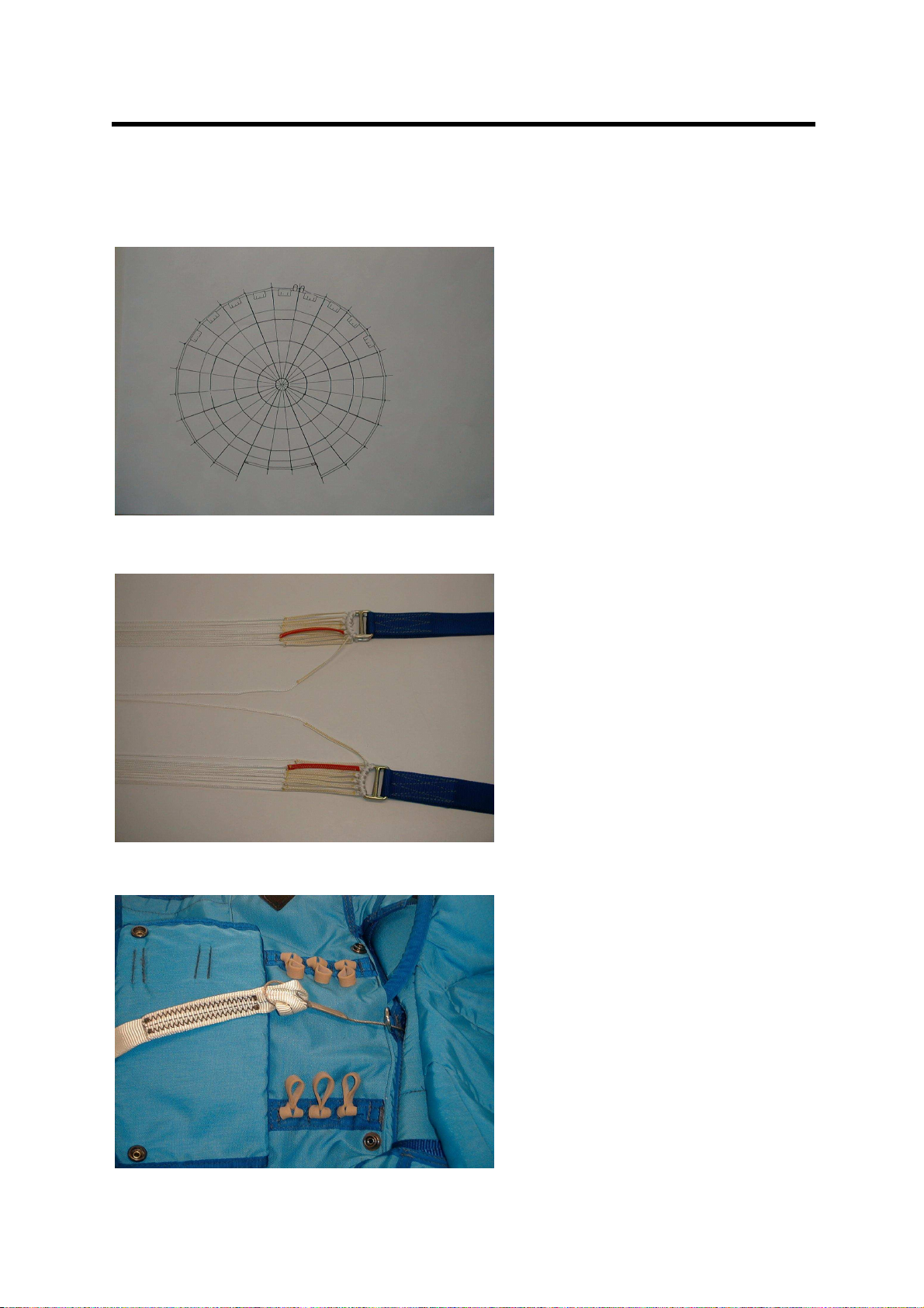
The round canopy (fig. 1) is designed as a conical canopy. It consists of 24 gores and is
made of nylon fabric (type 6,6) with differing air permeability having a lower air permeabil-
ity in the apex and skirt area. The canopy area is 41.5 m².
The skirt area of gores No. 24, 1 and 2 is constructed with a drive vent which provides
forward speed and turn control of the canopy.
The upper and lower peripheral edge of the canopy (apex and skirt) is reinforced by
means of tapes. Each third gore seam is reinforced by a longitudinal tape. Continuous,
circular reinforcements are sewn onto the canopy between panels Nos. 2 and 3, 3 and 4
as well as 4 and 5.
Air pockets are sewn onto gores Nos. 9 to 17 on the canopy’s skirt to support the deploy-
ment process.
Two skirt retainers are sewn onto the skirt on the right-hand and left-hand side next to the
suspension line No. 12. Their task is to temporarily enclose the skirt area when the can-
opy is stretching and to counteract irregularities when the canopy is deploying.
The vent has a diameter of approx. 550 mm and is guyed with 6 vent lines.
The suspension lines connect the canopy to the harness. The free length of the suspen-
sion lines measured from the canopy skirt to the connector links on the risers is 4.75 m;
the free length of suspension lines Nos. 1 and 24 is 5.40 m. Suspension lines Nos. 2 and
23 are color-coded on the connector links and serve as control lines at the same time.
1.5.2 Pilot Chute
The pilot chute consists of an eight-part pilot chute canopy, the outer and inner cone, the
conical spring as well as the bridle.
A nylon fabric (F 111) with low air permeability is used for the pilot chute canopy. The fab-
ric of the cone parts has high air permeability. Pilot chute canopy and cone parts are rein-
forced by means of tape.
The conical spring is located inside the inner cone.
The apex area of the pilot chute canopy is reinforced to cover the spring and equipped
with two grommets to secure the pilot chute inside the container.
The longitudinal tapes of the outer cone form a loop on their lower end in which the bridle
is knotted into. It connects the pilot chute to the vent lines of the parachute canopy and
has a length of approx. 750 mm when knotted.

SPEKON GmbH
Owner’s Manual
Issue 9
Emergency Parachute January 2019
RE-5L
QD 200/0000-003-020 07/09 Page 7 of 26
1.5.3 Container
The container is designed flexibly. It is integral with the harness. The container base of se-
ries 4 is approx. 840 x 380 mm; the base of series 5 is 550 x 380 mm. It is made of para-
pack nylon duck fabric.
The key component parts of the container are:
-two main cuts with four container flaps;
-two rubber band attachment tapes for the inboard and outboard rubber bands to stow
the suspension lines on the base of the container;
-one suspension line cover with a sewn-in positioning ring which holds the pilot chute in
place;
-four positioning flaps to retain the single folds of the inserted canopy in place;
-one base with reinforcing metal plate;
-two side flaps with a guiding tunnel for the main lift web;
-manual and manual/automatic locking loop;
-back pad (with integrated seat pad in series 4);
-yoke;
-one protective ripcord housing for the ripcord;
-one static line pocket with padded protective cover flap for the manual/automatic
model.
The log book is stowed inside a pocket which can be found on the inner side of the back
pad.
The back pad consists of a special textile fabric that is highly breathable by means of a
special combination of material and bonding. It therefore avoids a build-up of heat and
leads off sweat from the body.
1.5.4 Harness
The harness connects the canopy to the user. If fitted correctly, it evenly distributes the
opening shock all over the body.
The key component parts of the harness are:
-main lift web;
-back strap;
-leg strap;
-two-piece chest strap;
-chest and leg pads;
-harness fasteners;
-ripcord pocket guiding tunnel with ripcord pocket.
The connection between the risers of both main lift webs and the suspension lines is
realized via the connector links. The main lift webs are designed as a sling seat on their
lower parts. The main lift webs are held in place on the container by the side flaps and can
be adjusted by shoulder adapters.
The back strap is integral with the container. Their ends are sewn up with the main lift web
whereas the connection to the main lift web is realized by means of an adjustable side
strap in the RE-5L series 5.
Fastening and adjustment points can be found on the chest strap as well as on the leg
straps. Quick release buckles (on customer’s request also snap hooks) are used as fas-
tening devices. The ripcord handle pocket can be found on the left main lift web. It is sewn
onto a guiding tunnel, which can slide along the main lift web.

SPEKON GmbH
Owner’s Manual
Issue 9
Emergency Parachute January 2019
RE-5L
QD 200/0000-003-020 07/09 Page 8 of 26
1.5.5 Locking Device
If desired, each of the RE-5L series can be delivered with manual opening option solely
as well as with the manual/automatic opening option.
The locking device of the manual model consists solely of the ripcord; the man-
ual/automatic opening option of ripcord and static line.
The static line has on its upper end a snap hook which can be hooked to the aircraft and
a loop-on cable knotted to it on the lower end.
2 Instructions for Packing and Pre-flight Procedures
2.1 Packing Tools
The parachute can be packed on a packing table or a field pack mat.
For packing, you need two temporary packing pins, two pull up cords and three shot bags.
2.2 Inspection
The emergency parachute must be thoroughly inspected before each packing.
Lay the entire parachute assembly down on the packing area and stretch it from the har-
ness to the canopy apex. Arrange entangled and twisted parts in proper order. Check the
right position by lifting up suspension lines Nos. 1 and 24 on the skirt and move along
these lines towards the D-rings with bar. The suspension lines are in the right position
when both suspension lines are free of twists and lying along the inside edge of the upper
risers (fig. 2). The inside area of the container base must face upwards in the process.
Recommended order during the inspection:
-Log book
-Parts of the locking device
-Canopy with suspension lines and pilot chute
-Container with harness, quick release buckles
Check particularly during the inspection:
- Log book for proper entries
-Textile component parts for tears, dirty marks, torn seams or other damage
-Metallic component parts for proper functioning, breaks, cracks or rust
-Parts of the locking device
Ripcord handle for cracks, wire cables for torn strands, locking pins for deformations;
solder points, grommets and locking loops for being in perfect condition
-Connection between pilot chute, bridle and canopy for perfect condition on the
attachment points; secured to the pilot chute with hand stitches
-Quick release buckles for proper functioning — buckle tongue engages perfectly with
the locking part of the buckle and the two rotary levers snap back into position; protec-
tive metal cover flap can be moved and all rivets and balls are still in place

SPEKON GmbH
Owner’s Manual
Issue 9
Emergency Parachute January 2019
RE-5L
QD 200/0000-003-020 07/09 Page 9 of 26
Any damage which has been discovered during the inspection must be repaired.
The at this time valid “Repair Instructions for Emergency and Personnel Parachutes”
(editor: SPEKON Sächsische Spezialkonfektion GmbH) must be followed if any repairs
need to be done.
2.3 Packing Instructions
2.3.1 Pre-packing Procedures
Attach the canopy’s apex to the end of the packing table by using a cord loop. Adjust the
main lift webs to size 5. Fold the positioning flaps and the suspension lines cover flap past
the center of the container.
Further pre-packing procedures differ depending on the chosen opening option.
-manual/automatic:
Open the static line pocket cover on the top flap and thread the loop-on cable, which is
fastened to the static line, through the metal guide ring on the upper edge of the con-
tainer. Continue to thread it through the guiding slot formed by two tapes into the in-
side of the container (fig. 3).
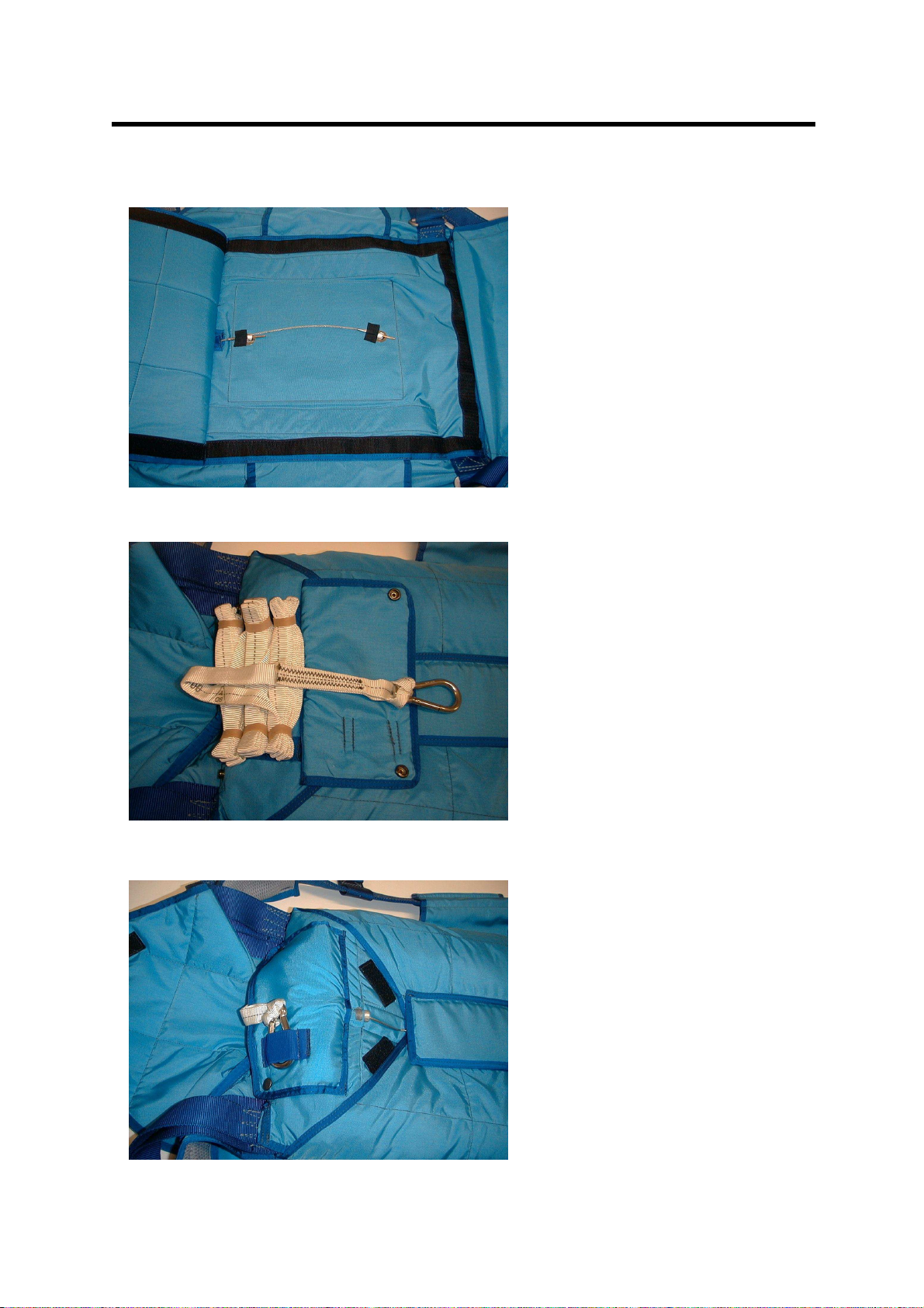
Invert the container: the back pad is facing upwards. Fold back the back pad.
Thread one locking loop man./auto. (50-164/02:00) through each of the two grommets
on the container base.
Put one ripcord locking pin through each of these two loops. Secure it with adhesive
tape to prevent it from being pulled out accidentally (fig. 4). Close the back pad again
and turn the container into its starting position.
Then stow the static line in the static line pocket.
Open the protective cover flap lowered over the two rows of inboard and outboard
rubber bands on the top flap and stow the static line in the inboard and outboard rub-
ber bands making “S”-folds (3-4 folds per rubber). The remaining free length is approx.
20 cm (fig. 5). Close the cover flap and put the snap hook under the rubber tape
located on the top side of the cover flap (fig. 6).
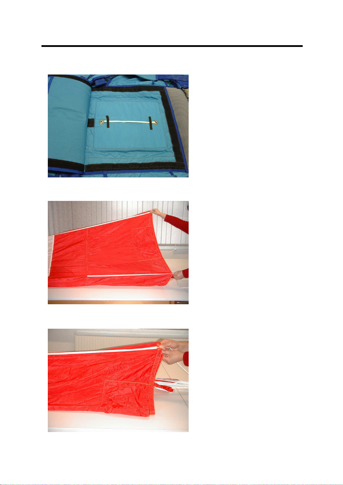
- manual:
There is no need for placing the loop-on cable in the container if the parachute is only
packed for the manual release.
Move one end of the locking loop man. (50-164/03:00) through each of the two grom-
mets on the container base and secure it with adhesive tape to prevent it from being
pulled out accidentally (fig. 7). Close the back pad again and turn the container to its
starting position.
2.3.2 Flaking, Pleating and Folding the Canopy
Tighten the whole system consisting of canopy, suspension lines and container and check
the suspension lines again.
Lift up the left-hand riser pair on the D-rings with bar and take suspension line No. 13,
which can be found at the inner side of the left-hand front riser, and pull this line down to
the left. Walk towards the skirt while tracing this suspension line with the left hand and the
remaining suspension lines of the left-hand riser pair with the right hand.
There, hold suspension line No. 13 out to the left and place the left-hand half of the can-
opy upon the right-hand half. Slide along the skirt from suspension line No. 13 to suspen-
sion line No. 14 with the right hand. Extend the right hand up to the right; the whole gore is

SPEKON GmbH
Owner’s Manual
Issue 9
Emergency Parachute January 2019
RE-5L
QD 200/0000-003-020 07/09 Page 10 of 26
tautened in the process (fig. 8). Then move the right hand quickly to the left and take sus-
pension line No. 14 with the left hand (fig. 9). All gores are flaked in this way. Deposit the
flaked canopy on the left-hand side of the packing table (fig. 10).
Now, pleat the canopy again gore by gore. The sketch below depicts the correct pleating
pattern:
This scheme shows the view on the skirt of the pleated canopy as seen from the
container’s direction. The points marked with numbers represent the respective
suspension lines.
Order the skirt and the suspension lines while pleating the single gores (fig. 11).
Start pleating the single gores by placing gore No.12 onto the packing surface and con-
tinue pleating until gore No. 1 is placed on top.
After placing gore No. 1 on top, weight down the right-hand half of the canopy with two
shot bags and place the left-hand half of the canopy upon the right-hand half that has
been already ordered. Fold back and order the left-hand half gore by gore in the same
way as you previously did with the right-hand half such that gore No. 24 is lying next to
gore No. 1 in the end.
Ensure that the air pockets located on the skirt of gores Nos. 9 to 17 are put tautly to the
outside direction when pleating the single gores.
Take the left-hand and right-hand suspension line bunches below the skirt and move them
slightly from side to side such that the gore seams are brought closely together inside the
canopy. Finally, check the lines again. The suspension lines Nos. 24 and 1 have to be on
top (fig. 12).
After the suspension lines have been checked, place gore No. 24 onto the right half of the
canopy. Then halve the gores with a drive vent (gore 24, 1 and 2) by long folding them
past center of the canopy. Now, place gore No. 23 onto the right-hand canopy half over
the halved drive gores to cover the drive vent. Then place the skirt retainers by turning up
these fabric bands towards the canopy apex (fig. 13). Starting with the right half of the
canopy, fold the lower lateral bands at 45 degrees so that they lie parallel to the suspen-
sion lines (fig. 14).
After folding the lower lateral bands on the left (fig. 15), divide the canopy in thirds by long
folding first the right-hand and then the left-hand half of the canopy past center (fig. 16).
Use shot bags to hold the folded canopy in place. Remove the cord loop from the
canopy apex.

SPEKON GmbH
Owner’s Manual
Issue 9
Emergency Parachute January 2019
RE-5L
QD 200/0000-003-020 07/09 Page 11 of 26
2.3.3 Riser Placement
Lay the risers in the container in such a way that the D-rings with bar lie in pairs next to
the free ends of the securing straps which are sewn onto the container base. As fig. 17
shows, thread the free ends of the securing straps from the base up through the D-rings,
which lie in pairs on top of each other, between the straight side and the bar. Move it
around the upper D-ring bar and then on the side of the bar farthest from the suspension
lines through the lower ring from the top down. Next thread it upwards between the bar
and the round side of the lower D-ring. Finally move it outwards between both D-rings and
tighten it towards the suspension lines’ direction.
A strong clamping effect arises between securing straps and D-rings when the pack is
closed. Owing to this fixture, the risers cannot be pulled out of the pack by accident.
2.3.4 Stowing of Suspension Lines
Stow the suspension lines in the inboard and outboard rubber bands which are fixed to
the base of the pack tray.
Stow the suspension lines according to the following scheme:
12 13
10 11
8 9
1
7 6
5 4
3 2
Normally, you do not need band No. 13.
Unite the two suspension line bunches from the riser’s direction and stow them in the cen-
tral band (1) in the pack tray according to the scheme. Take the suspension line bunch
from this point on to the left-hand side of the pack tray and stow it in the outboard rubber
band in the lower corner (2). Continue to stow the suspension lines following the given
scheme (fig. 18). Then cover the stowed suspension lines with the protective cover held in
place by hook and loop fasteners (fig. 19).
2.3.5 Placing Canopy in Container
Make the first canopy fold along the right-hand side of the container in such a way that the
canopy skirt ends at the upper edge of the container. In the process, tilt the skirt at 180
degrees towards the container base.
Lay the folded canopy back to the top along the left-hand side of the container ensuring to
lay a sufficiently big curve such that the lower part is filled out completely. Secure the part
of the canopy that has already been placed on both sides by means of the two inner posi-
tioning flaps (fig. 20).

SPEKON GmbH
Owner’s Manual
Issue 9
Emergency Parachute January 2019
RE-5L
QD 200/0000-003-020 07/09 Page 12 of 26
Then make a fold with the remaining part of the canopy downwards along the left-hand
side and back to the top along the right-hand side. Lay a smaller curve at the lower turn:
both folds lie next to each other in the lower area of the container. Secure the remaining
part of the canopy on both sides by means of the two outer positioning flaps. Fold the
apex of the canopy past center when packing the RE-5L series 4 (fig. 21).
Pay attention to the following when packing the RE-5L series 5:
You cannot lay both folds next to each other in the lower part because the container is
shortened. Lay them on top of each other forming a small W at the lower edge of the con-
tainer while making the first fold (fig. 22).
After placing the canopy in the container, its remaining free length is approx. 50 cm. Halve
the apex area by folding it approx. in the middle (fig. 23) and lay it subsequently parallel
with the upper edge of the container (fig. 24).
2.3.6 Placing Pilot Chute and Closing Container
Thread one pull up cord through each free end of the locking loops.
RE-5L Series 4:
Lay the bottom flap over the placed canopy and close it with three press studs on each
side. The press stud sockets are located on the slim side flaps. Thread both locking loops
through the grommets by using the pull up cords and secure each one with a temporary
packing pin.
Close the top flap in the same way. Lay it towards the center of the container and close it
with three press studs on each side. In order to shorten the bridle, S-fold the lower bridle
part and put it under the top flap. Remove the upper temporary packing pin and thread the
locking loop through the grommet of the top flap; secure again with the temporary packing
pin (fig. 25).
RE-5L Series 5:
Lay the bottom flap over the placed canopy. Thread both locking loops through the grom-
mets by using the pull up cords and secure each with one temporary packing pin. In order
to shorten the bridle, S-fold the lower bridle part and lay it onto the folds. Cover it with the
top flap. Remove the upper temporary packing pin and thread the locking loop through the
grommet of the top flap; secure again with the temporary packing pin.
Since the container is shorter, both container flaps are not closed with press studs in the
series 5.
Lead the bridle out of the container on the right side between bottom and top flap. Place
the bottom ring of the pilot chute conical spring on the sewn-in guide ring located in the
center of the container. In the process, ensure to align the two grommets on the pilot
chute with the two grommets on the container base. Tuck the canopy fabric of the pilot
chute under the top ring of the released conical spring. Tuck the fabric of the inner cone
between two coils approximately in the middle of the spring when compressing the pilot
chute. Thread the two locking loops through the grommets by using the pull up cords and
secure them with the temporary packing pins (fig. 26).
In the process, hold the pilot chute in such a way that the spring coils cannot push aside
and the canopy fabric cannot slip out.
After that, lay the left side flap first and then the right side flap over the pilot chute and se-
cure them with the temporary packing pins (fig. 27). In the process, also mate the hook
and loop fasteners of the RE-5L series 5 model. They can be found on the upper edge of
both side flaps and the top flap respectively.

SPEKON GmbH
Owner’s Manual
Issue 9
Emergency Parachute January 2019
RE-5L
QD 200/0000-003-020 07/09 Page 13 of 26
2.3.7 Completion
Secure the ripcord handle in the ripcord pocket on the harness and move the ripcord ca-
ble through the protective housing. Put the locking pins of the ripcord through the two
locking loops. Remove the temporary packing pins and pull up cords; seal the lower lock-
ing pin (fig. 28). Close the cover flap.
Close the external, padded flap (yoke), located above the static line pocket, with hook and
loop fastener and press studs.
Afterwards, invert the pack, open the back pad and remove the adhesive tape used to se-
cure the loop-on cable and the man. locking pin respectively. Seal the lower locking pin
when packing the man./auto. opening option (fig. 29). Take the log book out of its pocket
located on the upper edge of the opened back pad, fill in all data and put it back. Close
the back pad.
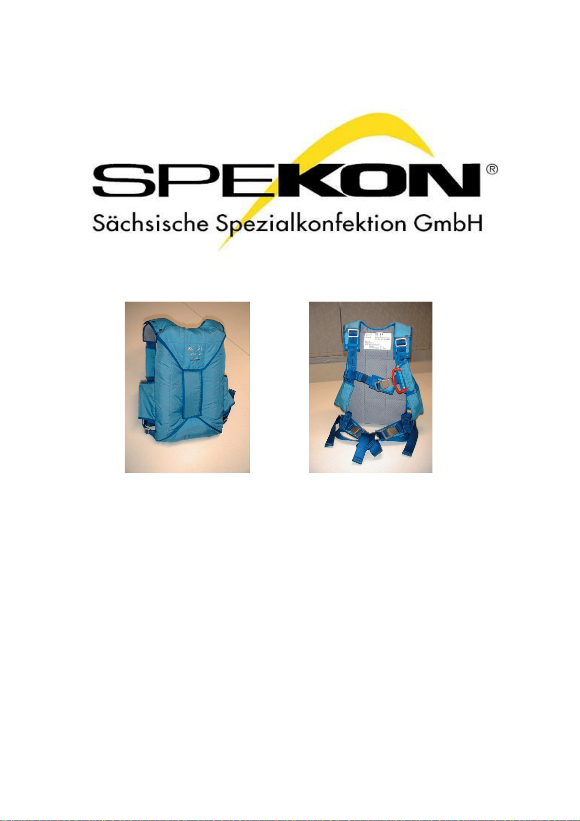
Fig. 30 shows the front of the packed RE-5L emergency parachute assembly series 5
ready for use
Fig. 31 shows the back of the packed RE-5L emergency parachute assembly series 5
ready for use.
Note:
If you want to open the emergency parachute automatically, un-mate the hook and loop
fastener of the external, padded flap and pull the snap hook out of the rubber tape. De-
pending on the position of the fixing point in the aircraft, pull out the static line on the left-
hand or right-hand side to the required length. Close the flap again.
Important:
- Use red seal thread (tensile strength 20-30N) and a lead seal for sealing the thread.
-Be sure to remove the adhesive tape in any case to avoid an increase of the opening
force.
-Record the repack and inspection in the parachute log book.
2.4 Putting on and Fitting of the Harness
In connection with the pack, the harness is designed in such a way that it enables you to
sit comfortably.
Put the harness on such that it doesn’t hinder you or feels too tight. Make sure that the
straps lie correctly in the guiding tunnels before putting on the harness. Then put the arms
through the gap left by the main lift web and the back strap, push the sling seat down-
wards and close the leg straps and the chest strap by means of the quick release buckles.
Adjust the main lift web on the adapters to custom fit the harness. In the process, ensure
that the straps have the same length (marked with numbers). Leg straps and chest strap
can be adjusted on the quick release buckles.
When the RE-5L series 5 is used, the pack can be hold in place additionally by pulling the
side straps.

SPEKON GmbH
Owner’s Manual
Issue 9
Emergency Parachute January 2019
RE-5L
QD 200/0000-003-020 07/09 Page 14 of 26
3 General Instructions
3.1 Parachute Steering
The RE-5L emergency parachute can be steered by pulling down suspension line No. 2
(right-hand side) if you want to turn right and suspension line No. 23 (left-hand side) if you
want to turn left. The suspension lines are indicated with colors.
If you pull both suspension lines at the same time, the forward speed will slow down and
the parachute will slide backwards respectively.
3.2 Landing
Pay particularly attention to the following when landing:
-Do not turn when you are landing.
-Do not pull both control lines or rear risers at the same time.
-Steer the canopy in such a way that you’re facing into the wind at 50 m above ground
level while landing when the wind speed is higher than 3m/s.
3.3 Storage and Maintenance
Maintenance, repairs as well as packing of the emergency parachute assembly may only
be done by personnel certified in the country of the parachute owner. The owner is
obliged to inform himself about respective laws and regulations. The SPEKON GmbH
company does only provide minimum standards in this manual.
3.3.1 Storage
The parachutes must be stored in dry, dust reduced rooms which can be ventilated well
and in which they are not exposed to direct sunlight. The temperature must be constantly
between 10°C and 25°C (50°F - 77°F) and the relative humidity between 30% and 70% in
these rooms.
Store the parachutes in cabinets or shelves taking the following minimum distances into
account:
- from the floor 25 cm
- from radiators 100 cm
- from external walls 100 cm
- from partition walls 50 cm
Store the parachute documents together with the parachutes.
Do not store substances in the parachute store whose composition may weaken and
destroy the parachute materials (e.g. greases, acids, oils or other chemicals). Keep the
store free of vermin.
3.3.2 Maintenance
All parachutes have to be inspected and aired periodically (at least once a year). Air at
least 6 hours. Hang the canopy up functionally by using a cord loop laid around the apex
to air it: the canopy is free along its entire length and can be repeatedly shaken out.
If you do not need the parachute, keep it packed for extended storage. For this purpose,
stretch out the canopy and fold it into thirds according to the packing instructions. Form a

SPEKON GmbH
Owner’s Manual
Issue 9
Emergency Parachute January 2019
RE-5L
QD 200/0000-003-020 07/09 Page 15 of 26
tail out of the suspension lines by daisy chain them and knot a suspension line piece
around the tail. Roll the parachute up when it is prepared in this way.
Put the harness in the carrying bag in such a way that the harness hardware does not
touch the canopy and the spring type pilot chute lies freely without pretension.
If the parachute has been dirtied owing to contaminated water, boggy or muddy ground,
rinse it while changing the water several times. Then air it to dry without twisting the can-
opy in the process. The same applies if the canopy has got in contact with sea water.
Remove oil or grease soiling carefully with mild detergent and rinse with water.
4 Maintenance and Repair
Emergency parachutes must be inspected periodically and if necessarily are repaired.
The inspection can be carried out by the manufacturer, a certified aeronautical engineer-
ing company or a parachute rigger certified for that.
A Authorized release certificate must be issued for the inspection carried out.
4.1 Inspection Cycle
The periodic inspection has to be done after twelve months at the latest.
If the inspection interval is not followed, after an emergency bailout, extensive repairs and
modifications and as directed by the aviation authority, a comprehensive inspection must
be carried out.
4.2 Scope of Inspection
4.2.1 Canopy with Suspension Lines
-Visually inspect the gores and panels for yarn slippage; tears, holes and friction burns;
stains and other damage.
-Visually inspect all tapes for holes, friction burns, tears and other damage.
-Visually inspect the seams for thread breakage, missing or loose stitches and friction
burns.
-Visually inspect the suspension lines for chafing and fraying; friction burns and torn
threads; knots or loops and other damage.
-Visually inspect the zig-zag stitching.
4.2.2 Pilot Chute
-Visually inspect the pilot chute canopy for fabric damage like shifted threads, holes
and friction burns.
-Visually inspect the reinforcement tapes and bridle for damage.
-Check the attachment points of pilot chute, bridle and canopy.
-Visually inspect the stitching.
-Check the conical spring for spring force, deformation and tight press sleeves.
-Visually inspect the hand stitches on the lower (small) ring of the conical spring.
-Check that grommets are not damaged and not loose.

SPEKON GmbH
Owner’s Manual
Issue 9
Emergency Parachute January 2019
RE-5L
QD 200/0000-003-020 07/09 Page 16 of 26
4.2.3 Container and Harness
-Visually inspect the fabric, pads and ripcord pocket as well as tapes and webbing for
tears and holes; chafing and fraying; stains and other damage.
-Visually inspect all stitching for missing or loose stitches, thread breakage and general
condition.
-Check that the inboard and outboard rubber bands for stowing the suspension lines
and the static line respectively are complete and not damaged.
-Check the hook and loop fastener for proper functioning.
-Visually inspect the locking loops for damage.
-Check all hardware for corrosion.
-Check the protective ripcord housing for dents and damage.
-Check that the grommets are not loose and not deformed.
-Check the press studs and quick release buckles for proper functioning.
4.2.4 Locking Device
-Visually inspect the cables for loose or broken strands and corrosion.
-Visually inspect the locking pins for deformation, proper fit, corrosion and condition of
the soldering.
-Visually inspect the ripcord handle for deformations, cracks or breaks.
-Check the static line for damage and condition of the seams. Check the attachment
points of snap hook, line and loop-on cable. Check the snap hook for proper function-
ing, damage and corrosion.
Check the locking device for proper functioning using a packed parachute.
The pull force has to be at last 7 daN and may not exceed 15 daN.
4.2.5 Miscellaneous
-Check that the all measures done are completely documented.
-Check that the parachute is marked and this marking corresponds with the documen-
tation.
The periodic inspection has to be recorded in the log book. In addition, write an inspection
report.
Major repairs and changes have to be recorded in the EASA Form One form. This applies
also for carrying out Airworthiness Directives (AD) if a test certificate is demanded by this
AD.
4.2.6 Repair
The at this time valid “Repair Instructions for Emergency and Personnel Parachutes”
(editor: SPEKON Sächsische Spezialkonfektion GmbH) are obligatory if any repairs of the
RE-5L emergency parachute have to be done.
SPEKON GmbH
Owner’s Manual
Issue 9
Emergency Parachute January 2019
RE-5L
QD 200/0000-003-020 07/09 Page 17 of 26
5 Figure Section
Fig. 1
Canopy
Fig
. 2
Suspension Line Check
Fig
. 3
man./aut.
Inserted Static Line
SPEKON GmbH
Owner’s Manual
Issue 9
Emergency Parachute January 2019
RE-5L
QD 200/0000-003-020 07/09 Page 18 of 26
Fig
. 4
man./aut.
Securing the Locking Pins
Fig
.
5
man./aut.
Stowing the Static Line
Fig. 6
man./aut.
Stowing the Snap Hook
SPEKON GmbH
Owner’s Manual
Issue 9
Emergency Parachute January 2019
RE-5L
QD 200/0000-003-020 07/09 Page 19 of 26
Fig
.
7
man.
Securing the Locking Loop
Fig. 8
Tautening the Gores
Fig. 9
Flaking the Gores

SPEKON GmbH
Owner’s Manual
Issue 9
Emergency Parachute January 2019
RE-5L
QD 200/0000-003-020 07/09 Page 20 of 26
Fig. 10
Placing the Folded Gores
Fig
.
11
Ordering the Gores
Fig. 12
Canopy Completely Pleated
This manual suits for next models
4
Table of contents
Popular Safety Equipment manuals by other brands


Kong
Kong PANIC 907.H00 manual

EUCHNER
EUCHNER NZ VZ AS Series operating instructions

Petzl
Petzl M37TL OMNI TECHNICAL NOTICE

Safety Xpress
Safety Xpress BOLSF100Y PRODUCT INFORMATION & INSTALLATION GUIDE

MSA
MSA PremAire Cadet Escape Operation and instructions

Guardian Fall Protection
Guardian Fall Protection GR6 Tie-Back SRL instruction manual


