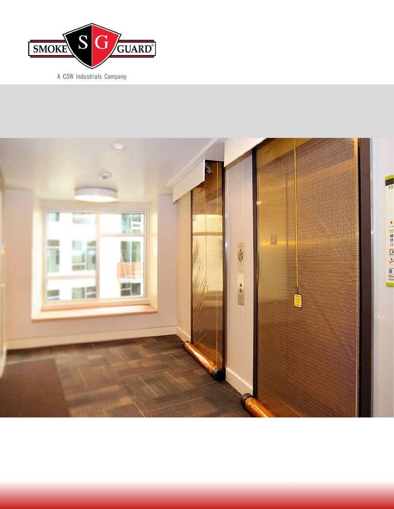
Smoke Guard M200 User manual

Model 200 & 400 |
Installation Manual
Smoke Curtain
287 N. Maple Grove. Boise, ID 83704
P. (800) 574-0330 F. (208) 639-7851
info@smokeguard.com

Doc #2401 – M200/M400 Installation Manual Rev. 9
2
Contents
1.0 – Introduction ............................................................................................................................................................. 4
2.0 – System Overview...................................................................................................................................................... 6
2.1 – Major Components .................................................................................................................................................... 6
2.2 – Optional Components ................................................................................................................................................ 7
3.0 – Install Preparation.................................................................................................................................................... 8
3.1 – Verify Field Preparation ............................................................................................................................................. 8
3.2 – Preparing the Housing for Mounting ....................................................................................................................... 10
4.0 – Mounting the Housing and Auxiliary Rails ............................................................................................................. 11
4.1 – Installing the Mounting Plate................................................................................................................................... 11
4.2 – Mounting the Housing ............................................................................................................................................. 12
4.3 – Installing the Auxiliary Rails ..................................................................................................................................... 13
5.0 – Installing the Screen............................................................................................................................................... 15
5.1 – Installing the Screen................................................................................................................................................. 15
5.2 – Attaching the Extension Springs (M400 only).......................................................................................................... 18
5.3 – Installing the Screen Rewind Switch ........................................................................................................................ 19
6.0 – Testing and Adjusting............................................................................................................................................. 20
6.1 – Testing the Installation............................................................................................................................................. 20
6.2 – Anchoring the Magnets............................................................................................................................................ 21
7.0 – Finishing the Installation ........................................................................................................................................ 22
7.1 – Preparing the Unit for Wiring................................................................................................................................... 22
7.2 – Installing the Dust Cover .......................................................................................................................................... 22
7.3 – Wiring....................................................................................................................................................................... 23
7.4 – Setting the Unit in a Ready State ............................................................................................................................. 24
7.5 – Final Testing ............................................................................................................................................................. 25
8.0 – Troubleshooting ..................................................................................................................................................... 26
8.1– Spotting an error....................................................................................................................................................... 26
8.2– Troubleshooting the M200 and M400 without battery............................................................................................ 26
8.3 – Troubleshooting the M400 with battery.................................................................................................................. 27
8.4 – Error Codes – M400 with Battery............................................................................................................................. 28
8.5 – Solutions Guide ........................................................................................................................................................ 29
9.0 – Contact Smoke Guard ............................................................................................................................................ 31
10.0 – Glossary.................................................................................................................................................................. 32
11.0 – Suggested Anchors................................................................................................................................................. 34

Doc #2401 – M200/M400 Installation Manual Rev. 9
3

Doc #2401 – M200/M400 Installation Manual Rev. 9
4
1.0 – Introduction
This is the official installation manual for the Model 200 and 400 Smoke Curtains from Smoke Guard,
Inc.
NOTE: This model shows a Model 400 (without a backup battery). Installation of the Model 200 is identical
but it does not have a door closer mechanism or door springs.
The Smoke Guard Models 200 & 400 Smoke Curtains (M200/M400) are motorized smoke protection systems
housed above an elevator. The M200 & M400 systems are rated to UL 1784 according to the requirements of
smoke and draft control assemblies defined in NFPA 105.
The smoke detector or other initiating device is part of the building smoke and fire alarm system and not a
component of the Smoke Guard system. In the event of an alarm, the initiating device signals the controller to
activate a DC motor as well as a damper and clutch (model dependent) to deploy a protective curtain. The
curtain unrolls to the floor with the curtain magnets adhering to either the elevator frame or auxiliary rails to
seal the opening. When not in use the M200/M400 is retracted into a housing unit which maintains the aesthetic
of the facility in which it is installed.
The system will also deploy in the event of a sustained power loss, with the exception of the M400 when
optioned with a battery for backup power. This can prevent fault deployments in the event of AC power loss.
However, the battery is for emergencies only.
Installation of the Smoke Guard system requires a moderate amount of construction and electrical experience as
well as a variety of tools and hardware, both standard and specialty. Installers should be comfortable drilling
through various materials (metal, sheetrock, wood, etc.), utilizing anchors appropriate for the backing material,
using a hand riveter, and terminating low voltage wires. Below is a list of tools and hardware required in
addition to the material supplied by Smoke Guard:
•25-foot tape measure
•Permanent marker
•Portable hand drill or driver
•Portable angle-head drill or attachment (for hard-lid installations)
•Drill bits (1/8” for rivets, remaining sizes depend on anchors utilized)
•#2 Philips bit
•Flat and Philips head screwdrivers
•Hand riveter
•Chalk line
•4-foot magnetic level
•Torpedo level
•Tin snips
•Portable bandsaw
•Wire strippers
•Utility knife
•5/16” and 7/16” combination wrenches
•3/32”, 1/8”, 5/32”, 5/16” ball head hex wrenches
•Grounded extension cord

Doc #2401 – M200/M400 Installation Manual Rev. 9
5
•Screen mounting brackets (J-hooks, available for purchase from Smoke Guard)
•Mounting plate anchors suitable for backing (qty. 6, see section 11 for suggested anchors)
•Plastic shims for leveling housing
•Rail backer anchors suitable for backing (qty. 10, see section 11 for suggested anchors)
Installation should occur after the installation of the elevator frame and surrounding drywall, but prior to ceiling
installation and any painting around the elevator.
NOTE: Follow applicable safety procedures during installation, including the appropriate use of any personal
protective equipment (e.g. hard hat, safety goggles, gloves, etc.). Exercise caution when using a ladder or
stepladder and ensure you get assistance and use proper lifting techniques when carrying and mounting the
housing.

Doc #2401 – M200/M400 Installation Manual Rev. 9
6
2.0 – System Overview
The M200/M400 Smoke Curtain is a motorized smoke protection system housed in the ceiling of a building.
The system uses a DC motor to deploy a specialized curtain into a strategic location. When not in use, the
M200/M400 is retracted into a housing unit which maintains the aesthetic of the facility in which it is installed.
Figure 1– The M200/M400 installed
2.1 – Major Components
Smoke Detector:The local smoke detector is the recommended initiating device for the M200/M400.
AC Line In:The M200/M400 connects to the building 120 VAC for primary power. When optioned with a
backup battery the M400 can also operate on 240 VAC.

Doc #2401 – M200/M400 Installation Manual Rev. 9
7
Housing:The M200/M400 housing contains the control, drivetrain, and screen assembly (when retracted). The
dust cover and junction box are integral parts of the housing.
Mounting Plate (not shown):The mounting plate attaches directly to the backing material above the elevator
and provides the mounting interface for the housing.
DuraNet™ Screen Assembly: The transparent screen assembly forms the main smoke protection barrier from
the elevator shaft and allows visibility from the car onto the landing
Kevlar® Cables: The cables connect the screen threshold pulleys to the drivetrain in the housing to allow the
screen to retract and deploy.
Flexible Magnetic Edge: The magnets on either side of the screen assembly secure the screen to the auxiliary
rails or elevator frame. These magnets also allow for push through manual egress if necessary.
Screen Rewind Switch: The Screen Rewind Switch (SRS) allows egress from either side of the screen. When
pressed the screen will temporarily retract into the housing before redeploying.
Auxiliary Rail: Auxiliary rails provide a surface for the screen magnets to adhere to. The M400 can be
optioned to adhere directly to the elevator frame, which does not require the use of full length
auxiliary rails. In this configuration the auxiliary rails can also be used as stub rails to bridge the gap
from the housing to the elevator frame.
Auxiliary Rail Backer: If auxiliary rails are used, the backer is attached to the mounting surface during install.
Installation Kit (not shown): A variety of installation components is included with each unit. This kit includes
a roll of Kapton® tape for securing the SRS wiring, a bag of hardware for securing the screen and
housing, a pair of housing door clips for holding the door closed before permanent power is attached.
End of Line Diode (not shown): The end of line (EOL) diode allows for monitoring the integrity of the
initiating device circuit. The EOL diode is required for all installations, see the electrical guide for
more information. The EOL diode is shipped inside the housing junction box.
2.2 – Optional Components
The M400 may be shipped with the following optional components:
•Wall Activation Switch
•Controller Backup Battery

Doc #2401 – M200/M400 Installation Manual Rev. 9
8
3.0 – Install Preparation
3.1 – Verify Field Preparation
Prior to installing the Smoke Guard system, the general contractor prepares the site for installation.
Housing clearance – For each housing the general contractor provides a clearance above the elevator:
•Unobstructed, wall plumb, with no distortions
•No more than 10 feet (12 feet for M400 units ordered as such) from the floor to the bottom of the
housing
•At least 10 inches vertical and 12 inches projected from the mounting surface
•At least 2 inches wider than the housing, centered over the elevator door
•Mounting height marked with a chalk line
•Ceiling and grid removed from housing area
•Backing extending the full width and height of the clearance

Doc #2401 – M200/M400 Installation Manual Rev. 9
9
Curtain clearance – For each housing the general contractor provides a clearance on the landing side of the
elevator:
•Extending from the bottom of the housing to the floor along the full screen assembly width
•Centered over the hoistway frame
•Unobstructed, wall plumb, with no distortions
•Free of all obstructions and projections that exceed the housing return depth, including the elevator
position indicators, signs, and hall call stations
•Includes clearance for door swing; 7-1/4 inches
•With 2 inch wide backing for auxiliary rail backers extending the full height

Doc #2401 – M200/M400 Installation Manual Rev. 9
10
3.2 – Preparing the Housing for Mounting
The screen assembly ships inside the housing, remove carefully to avoid damaging the screen and/or the
housing components.
NOTE: The door closer extension springs (M400 only) and the up-limit switch are not attached in their
operating positions as shipped. This allows for safe removal of the screen assembly. They will be installed to
their final location later in the installation process.
Removing the screen and mounting plate from the housing:
1. With the housing return side on the saw horses, remove the dust cover
2. Push the door open and gently roll the screen out through the housing door
3. Using the 5/32” hex wrench loosen and remove the machine screws holding the mounting plate to the
housing and remove the mounting plate

Doc #2401 – M200/M400 Installation Manual Rev. 9
11
4.0 – Mounting the Housing and Auxiliary Rails
4.1 – Installing the Mounting Plate
Required parts, tools, and hardware:
•Mounting plate
•25-foot tape measure
•Torpedo level
•Chalk line
•4-foot magnetic level
•Permanent marker
•Corded or cordless hand drill or driver
•Drill bits for mounting plate anchors
•Mounting plate anchors
•Plastic shims for leveling housing
Installing the mounting plate:
1. Mark the mounting height over the elevator opening
2. Mark the center of the elevator frame at mounting height and a centerline on the mounting plate
3. Lift the mounting plate, place against the wall, and use the marks from steps 1 and 2 to center and install
with the bottom edge 3/4” above mounting height
4. Temporarily anchor in place through the center hole near the top of the plate
5. Level the plate and shim to ensure a LEVEL and FLAT surface
6. Permanently anchor the plate to the wall through 6-8 of the holes in the plate

Doc #2401 – M200/M400 Installation Manual Rev. 9
12
4.2 – Mounting the Housing
Required parts, tools, and hardware:
•Housing (dust cover and screen assembly removed per section 3.2)
•Machine screws (originally removed per section 3.2)
•5/32” ball head hex wrench
Installing the mounting plate:
1. Lift the housing onto the mounting plate, hooking the lip at the top of the housing over the plate
2. Adjust the position of the housing so the center mark inside the housing aligns with the center of the
elevator frame
3. Verify that the slots in the back of the housing line up with the threaded standoffs on the mounting plate
4. Fasten the housing to the mounting plate using the machine screws into the threaded standoffs

Doc #2401 – M200/M400 Installation Manual Rev. 9
13
4.3 – Installing the Auxiliary Rails
Auxiliary rails are required on M200s and optional on M400s depending on the installation. The auxiliary rail
backer is anchored to the wall along the sides of the elevator frame. The auxiliary rail is then attached to the
auxiliary rail backer to create the curtain sealing surface. If the elevator frame is nonferrous, not flat, less than 2
inches wide, or recessed or flush with the wall, the installation will require auxiliary rails to function properly.
If the elevator frame is ferrous (e.g. 400 series stainless steel), flat, and at least 2 inches wide it can be used as
the curtain sealing surface for an M400. In this case you can utilize stub rails extending from the top of the
elevator frame to the bottom of the housing to provide a continuous seal. Stub rails are attached to a backer that
is anchored in place much like an auxiliary rail. Stub rails are not required if the gap between the head of the
elevator frame and the housing is 1/4” or less.
NOTE: When measuring for the length of the rails, be sure to account for the thickness of the flooring that may
be added later. A floor material sample is ideal to ensure correct measurements.
Required parts, tools, and hardware:
•Auxiliary or stub rail backers
•Auxiliary or stub rails
•Flooring sample if available
•25-foot tape measure
•4-foot magnetic level
•Permanent marker
•Tin snips
•Portable bandsaw
•Hand riveter
•#44 rivets (qty. 16)
•Corded or cordless hand drill or driver
•Drill bits for auxiliary rail backer anchors
•Auxiliary rail backer anchors
•Driver for auxiliary rail backer anchors
•Plastic shims for leveling housing
Installing the auxiliary rail backers:
1. For auxiliary rails measure the distance between the floor and the bottom of the housing. For stub rails
measure the distance between the head of the elevator frame and the bottom of the housing.
2. Use the measurement from step 1 to cut the rail backers to length with tin snips.
3. For auxiliary rails drill 4-6 evenly spaced holes on each rail backer for wall anchors. For stub rails drill
at least 2 evenly spaced holes, ideally ~1” from each end of the rail backer.
4. Align the center of a rail backer with the right rail backer centerline marked inside the housing.
5. Level the rail backer vertically.
6. Mark and drill anchor holes in the wall using the rail backer as a template.
7. Drive anchors through the drilled holes to anchor the rail backers in place.
8. Repeat steps 4-7 for the left rail backer.

Doc #2401 – M200/M400 Installation Manual Rev. 9
14
Installing the auxiliary rails:
1. Use the height of the right rail backer to determine the cut length for the auxiliary rail.
2. Mark the cut length on the auxiliary rail and use a bandsaw to cut to length. The auxiliary rails are one
of the most visible components, take care to make a clean, level cut.
3. Repeat steps 1 and 2 for the left auxiliary rail.
4. Drill 3-6 evenly spaced holes along the outside edge of each rail. Bias these holes towards the face of the
rail to allow enough room for a hand riveter when installing.
5. Place both auxiliary rails over the rail backers, making sure to orient the factory cut edge against the
housing for a clean interface without any gaps.
6. Hold each auxiliary rail so it is fully seated on the rail backer, flush with the wall, and flush with the
bottom of the housing.
7. Verify that the rails are vertically level.
8. Use the holes drilled in step 4 as a template to drill mating holes in the rail backers.
9. Rivet the auxiliary rails in place.

Doc #2401 – M200/M400 Installation Manual Rev. 9
15
5.0 – Installing the Screen
5.1 – Installing the Screen
Required parts, tools, and hardware:
•Screen
•Screen mounting brackets (J-hooks, available for purchase from Smoke Guard)
•Installation kit
•#10 x 3/4” hex-head self-drilling screws (qty. 2)
•Corded or cordless hand drill or driver
•#2 phillips bit
•Grounded extension cord
Attaching the J-hooks:
1. Clean any debris off the magnets of the J-hooks to avoid scraping the auxiliary rails or elevator frame.
2. Carefully place each hook on its auxiliary rail butted against the outer edge.
3. Move each hook so the top butted against the housing to align them vertically so the screen will sit level.
Installing the screen:
1. Orient the screen so the loose end unrolls up from the back of the roll.
2. Lift the screen and place onto the J-hooks, allowing each threshold pulley to rest in the hook.
3. Remove the nut from the center stud towards the bottom of the back of the housing.
4. Unroll the screen by lifting the top bar and allowing the pulleys to rotate in the J-hooks. Lift the top bar
until you can slide the center hole of the top bar over the center stud in the housing.
5. Reinstall the nut on the center stud.
6. Grab the magnets near both sides of the top bar and pull outwards so the screen is taut and the screen
overlaps the auxiliary rails or the elevator frame by 1/4” on each side.

Doc #2401 – M200/M400 Installation Manual Rev. 9
16
NOTE: Power is not required to attach and adjust the threshold cables on the M200 or M400 without battery.
For the M400 with battery power is required to jog the motor and unwind/rewind the cables. This can be
accomplished by plugging the pigtail coming out of the junction box into a grounded extension cord.
Attaching the threshold cables:
1. Remove the tape holding the cable in place on the drive pulleys inside the housing.
2. Unwind enough cable to reach the pulleys on the threshold.
3. Slide the cable (before the crimp bead) into the slot in the threshold pulley on both sides.
4. Rewind the cables until the tension seats the crimp beads snugly.
5. Unwind enough cable to allow multiple wraps around the threshold pulleys.
6. Wrap each cable twice around each threshold pulley, over the top towards the wall (clockwise on the
right pulley, counterclockwise on the left pulley).
7. Rewind the cable to take up any cable slack that remains.
Installing the up-limit switch:
1. Cut the zip ties holding the up-limit switch in its shipping position.
2. Use the included hardware in the installation kit to fasten the up-limit to the bracket. The bracket is
located on the left side of the lower front support bar.
Adjusting and anchoring the screen (M200 and M400 without battery):
1. Manually rewind the cables by rotating the drive axle by hand until slack is removed and cable is taut.
Remove the J-hooks and release the axle to allow the screen to fully deploy to the floor.
2. Plug the pigtail coming out of the housing junction box into a grounded extension cord to provide
temporary power to the unit.
3. Press the screen rewind switch (SRS, temporarily bagged and attached to the top of the housing) to
retract the screen into the housing temporarily. The screen will deploy again after a brief pause.
4. Verify that the screen is properly covering the opening by checking the following:
oThe threshold should hit the floor on both sides of the screen.
oBoth magnets should fully cover the rails along their entire length.

Doc #2401 – M200/M400 Installation Manual Rev. 9
17
If necessary adjust the screen manually by manipulating the magnets and/or pivoting the whole
assembly slightly around the center stud in the housing.
5. Once the screen is deploying correctly use the SRS to cycle the unit 2-3 more times. Each time verify
the screen coverage per step 5.
6. When you are satisfied with the screen installation, secure the top bar to the housing through one of the
holes on both sides using the #10x3/4” hex head self-drilling screws.
7. Cycle the screen 2-3 more times, again verifying the screen coverage per step 5.
Adjusting and anchoring the screen (M400 with battery):
1. If power is not already present, plug the pigtail coming out of the housing junction box into a grounded
extension cord to provide temporary power to the unit.
2. Rewind the cables by using the control jog buttons (switches 1 and 2) until the screen pulleys lift off of
the J-hooks. Remove the J-hooks and jog the screen to the floor.
3. Jog the screen up to it into the housing and confirm the door fully closes prior to actuating the up-limit
switch.
4. If the door did not fully close, bend the tang of the up-limit switch back slightly to allow the screen to
retract further into the housing before the switch is triggered. Repeat step 3 and continue to adjust as
necessary until the door closes completely on retract.
5. Jog the screen to fully deployed and verify that it is properly covering the opening by checking the
following:
oThe threshold should hit the floor on both sides of the screen.
oBoth magnets should fully cover the rails along their entire length.
If necessary adjust the screen manually by manipulating the magnets and/or pivoting the whole
assembly slightly around the center stud in the housing.
6. Once the screen is deploying correctly use the jog buttons to deploy the screen to the floor. Perform a
calibration by holding the test deploy switch (switch 3) for 3 seconds. The screen will retract slowly into
the housing. Again confirm the door is fully closed.
7. Use the test deploy switch to cycle the unit 2-3 more times. Each time verify the screen coverage per
step 5.
8. When you are satisfied with the screen installation, secure the top bar to the housing through one of the
holes on both sides using the supplied phillips self-drilling screws.
9. Cycle the screen 2-3 more times with the test deploy switch, again verifying the screen coverage per step
5.

Doc #2401 – M200/M400 Installation Manual Rev. 9
18
5.2 – Attaching the Extension Springs (M400 only)
The Smoke Guard Model 400 is shipped with the door closer extension springs disconnected to allow for
removal of the screen.
Attaching the door extension springs:
1. With the dust cover still removed close the housing door.
2. Remove the nuts on the housing door studs.
3. Slide the unattached eye on the end of the extension springs over the housing door studs.
4. Reinstall the nuts on the housing door studs and hand tighten.
Adjusting the door closer:
1. Retract the screen into the housing.
2. If the door did not fully close, deploy the screen and bend the tang of the up-limit switch back slightly to
allow the screen to retract further into the housing before the switch is triggered.
3. Repeat steps 1 and 2 and continue to adjust as necessary until the door closes completely on retract.

Doc #2401 – M200/M400 Installation Manual Rev. 9
19
5.3 – Installing the Screen Rewind Switch
The screen rewind switch (SRS) initiates a temporary retract of a deployed screen, allowing someone to pass
through the opening. The screen will redeploy as long as the initiating device remains active. There is a delay of
several seconds after deployment before the SRS will operate, this prevents accidental activation during
deployment.
During shipping the switch, backside label, and coiled up wiring are stored in a bag that is attached to the inside
of the housing. When you are ready to install the switch, cut the zip ties that hold the bag and wire in place and
allow the switch to fall into place.
Required parts, tools, and hardware:
•Screen rewind switch (pre-wired to controller)
•Kapton® tape (included in installation kit)
•Zip ties and mounting brackets (included in installation kit)
•Permanent marker
•Utility knife
•25-foot measuring tape
NOTE: Any alteration to a place of public accommodation or a commercial facility shall be made so as to
ensure that, to the maximum extent feasible, the altered portions of the facility are readily accessible to and
usable by individuals with disabilities, including individuals who use a wheelchair.
Installing the screen rewind switch:
1. Mark the center of the screen 42” up from the floor on the landing side of the screen.
2. Peel off the backing from the adhesive of the wired portion of the switch.
3. Keep both the screen and switch as flat as possible and mount the center of the switch directly over the
mark made in step 1.
4. Peel off the backing from the adhesive on the backside label of the switch.
5. Again, keep both the screen and switch as flat as possible, mount the backside label of the switch on the
elevator side of the screen, directly opposite the wired portion of the switch.
6. Use the Kapton® tape to attach the wire to the screen running directly up from the SRS. Take care to
avoid putting too much tension on the wire.
7. Coil up any remaining wire in the housing and mount to the housing using zip ties and mounting
brackets.

Doc #2401 – M200/M400 Installation Manual Rev. 9
20
6.0 – Testing and Adjusting
6.1 – Testing the Installation
Cycle testing the unit during installation allows testing of the screen assembly seal, the diode, and the screen
rewind switch.
Required parts, tools, and hardware:
•End of line diode
•Door clips (included in installation kit)
Conducting cycle tests (M200 and M400 without battery):
1. Located and remove the EOL diode. It will be in the junction box on the side of the housing or in the
bag with the screen rewind switch.
2. If the unit is powered on, temporarily turn it off using the switch on the side of the control.
3. Install the diode between the two low voltage wires in the junction box.
4. Turn the power back on. The screen will retract into the housing.
oIf the screen retracts unevenly, cycle power a few times to deploy and retract the screen and
allow the cables to stack properly on the pullies.
5. Disconnect one side of the diode from the low voltage wires. The screen will deploy.
6. Inspect the screen to ensure that the magnets fully cover both auxiliary rails (or the elevator frame) and
that the threshold seals along the full width of the screen. If either side of the threshold sits more that
1/8” off the floor, adjust the screen assembly accordingly.
7. Cycle the unit 2-3 more times by connecting and disconnecting the diode. Verify the screen seal after
each deploy.
8. Leave the diode disconnected so the screen will remain deployed. Press the screen rewind switch. The
screen should retract, pause briefly, and redeploy.
9. Repeat the SRS test on the elevator side of the screen.
Conducting cycle tests (M400 with battery):
1. Remove the EOL diode from the junction box on the side of the housing.
2. If the unit is powered on, temporarily turn it off using the power switch on the control. Ensure the
battery is also disconnected.
3. Install the diode between the two low voltage wires in the junction box.
4. Restore power to the unit. The screen will retract into the housing. Do not reconnect the battery.
oIf the screen retracts unevenly, cycle power a few times to deploy and retract the screen and
allow the cables to stack properly on the pullies.
5. If the unit hasn’t been calibrated yet use the jog buttons (buttons 1 and 2) to deploy the screen to the
floor. Perform a calibration by holding the test deploy switch (button 3) for 3 seconds. The screen will
retract slowly into the housing.
6. Disconnect one side of the diode from the low voltage wires. The control will signal error 3 by sounding
an alarm and signaling the error code on the LEDs.
7. Reconnect the diode. Push the test deploy switch once to silence the alarm, and again to clear the error.
The system will perform a self-test and return to an armed state.
8. Press the test deploy switch to deploy the screen. Inspect the screen to ensure that the magnets fully
cover both auxiliary rails (or the elevator frame) and that the threshold seals along the full width of the
This manual suits for next models
1
Table of contents
Other Smoke Guard Safety Equipment manuals
Popular Safety Equipment manuals by other brands

Primal Vantage
Primal Vantage Field&Stream HEH00623 Instruction and safety manual
Kong
Kong Target Pro manual

Harken Industrial
Harken Industrial ninja quick start guide

KwikSafety
KwikSafety SCORPION KS6604T Instructions for use
Husqvarna
Husqvarna 198 Operator's manual

OEZ
OEZ OD-FH00-KR Instructions for use

Petzl
Petzl EN 564 Instructions for use
EUCHNER
EUCHNER SGP-TW Series operating instructions

3M
3M DBI SALA 2000005 User instruction manual

Perma child safety
Perma child safety 2727 instruction manual

Honeywell
Honeywell Miller Twin Turbo G2 Connector User instruction manual

Reliance
Reliance Skyloc 4 Series Instructions for use
