CS.......................................................................................................
8 - SPECIFICKÉ INFORMACE
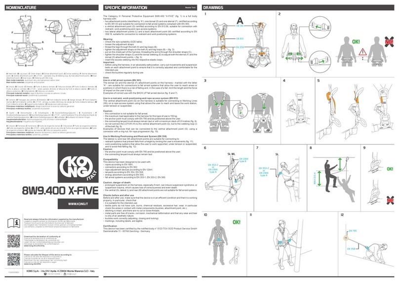
Osobní Ochranný Prostředek třídy III, 907.HOO nazvaný PANIC (obr. 1), je karabina, která je ve
shodě s normou EN 12275:13 a je vhodná pro přímé nebo nepřímé připojení ke kotvicímu bodu.
Je vybavena pojistkou západky, která umožňuje udržet západku otevřenou (obr. 2A) a uvolnit ji a
zablokovat v zavřené poloze v okamžiku, kdy je aplikována zátěž na samotnou karabinu (obr. 2B).
Při použití ve spojení s trubkovým páskem, který je zpevněn ohebnou tyčkou, umožňuje snadno
dosáhnout vzdálenějších spitů (kotvicích bodů) (obr. 3).
Důležitá informace: Pozorně vyhodnoťte vhodnost zvoleného kotvicího bodu na základě aplikace, pro
kterou je určen. Osobně se ujistěte, že:
- expres set zůstane pod kotvicím bodem (obr. 4),
- se mohou karabiny zasunuté do ukotvení volně pohybovat a nastavit se do předpokládaného směru
aplikace zátěže se vždy dokonale zavřenou západkou.
Obr. 1 - Terminologie a základní materiály jednotlivých součástí: (A) Tělo z hliníkové slitiny,
(B) Západka z nerezavějící oceli, (C) Pojistka západky z bronzové slitiny, (D) Trubkový pásek z
polyamidu (pouze pro verzi 907SET).
Příklady správného použití:
Obr. 5 - poloha, která nabízí maximální odolnost. Upozornění: spojení se širokými prvky snižuje
odolnost karabiny (obr. 6) a může negativně ovlivnit odjištění a uzavření západky (obr. 7)-
Obr. 8 - správné vložení karabiny do spitu a postupového lana do expres setů.
Obr. 9 - Použití expres setů usnadňuje posuv lana.
Příklady nesprávného a nebezpečného použití:
Obr. 10 - chybné vložení konektoru do spitu,
Obr. 11 - chybné vložení lana do expres setu. Upozornění: případný pád by mohl způsobit
vyklouznutí lana,
Obr. 12 - při stoupání si nikdy nepomáhejte uchopením karabin tak, jak znázorňuje obrázek 12.
Příklady možných náhodných otevření:
Obr. 13 - dynamický náraz na skálu,
Obr. 14 - skalní výčnělek, který otevře západku,
Obr. 15 - vibrace způsobené posuvem lana při pádu,
Příklady nesprávného a nebezpečného umístění:
Obr. 16 - příliš velké ukotvení neumožní zavření západky,
Obr. 17 - polohy způsobující boční a/nebo příčnou námahu a/nebo kroucení,
Důležitá informace: před použitím karabin pro závěsné soupravy vypočítejte skutečné zátěže, kterým
budou karabiny vystaveny (obr. 18); tyto zátěže nesmí nikdy překročit ¼ zátěže vyznačené na karabině
(SWL 1:4),
9 - KONTROLY PŘED POUŽITÍM A PO POUŽITÍ
Zkontrolujte a ujistěte se, že:
- je výrobek vhodný pro zamýšlené použití,
- karabina nebyla vystavena mechanickým deformacím a nevykazuje známky prasklin a opotřebení,
- západku lze úplně otevřít (obr. 2A),
- pojistka západky:
- udrží západku v otevřené poloze (obr. 2A),
- uvolní západku a zablokuje ji v zavřené poloze v okamžiku aplikace zátěže na karabinu (obr. 2B),
- se na pásku nevyskytují:
- řezy, opotřebení nebo škody způsobené používáním, teplem, chemickými produkty, ostrými
hranami apod.; zkontrolujte zejména součásti, které přicházejí do styku s karabinami,
- poškozené švy: pozor na odřezané nebo uvolněné nitky.
Před každým použitím proveďte v jednoznačně bezpečné poloze zkoušku odolnosti karabiny, a to tak,
že ji zatížíte svou hmotností.
10 - CERTIFIKACE
Toto zařízení bylo certikováno akreditovanou institucí č. 0123 - TÜV SÜD Product Service GmbH
Daimlerstraße 11 - 85748 Garching - Německo
Odkaz na text: ITALSK
DE........................................................................................................
8 – SPEZIFISCHE INFORMATIONEN
Die persönliche Schutzausrüstung (PSA) in Klasse III, 907.HOO bezeichnet als PANIC (Abb. 1) ist ein
Karabiner nach EN 12275:13 um sich direkt oder indirekt an einem Anschlagpunkt einzuhängen. Er ist
mit einer Klemmvorrichtung des Schnappers versehen, mit der der Schnapper offen gehalten (Abb. 2A)
und freigegeben werden kann und mit der er in geschlossenen Position blockiert werden kann, wenn an
den Karabiner eine Last angelegt wird (Abb. 2B).
In Verbindung mit der Schlauchschlinge, die von eine exiblen Stab versteift wird, kann man damit leicht
die entfernteren Anschlagpunkte (Abb. 3) erreichen.
Wichtig: Bewerten Sie sorgfältig die Eignung des gewählten Anschlagpunkts in Funktion der
vorgesehenen Anwendung. Insbesondere immer sicherstellen, dass:
- Die Umlenkung immer unter dem Anschlagpunkt bleibt (Abb. 4),
- die in die Anschlagung eingesetzten Karabiner sich frei bewegen und sich immer mit perfekt
geschlossenem Schnapper in der vorhersehbaren Richtung der Lastanwendung positionieren
können.
Abb. 1 –Terminologie und wichtigste Materialien der Teile: (A) Körper aus Aluminiumlegierung,
(B) Schnapper aus Edelstahl, (C) Klemmvorrichtung des Schnappers aus Bronzelegierung, (D)
Schlauchschlinge aus Polyamid (nur bei Version 907SET).
Beispiele für die korrekte Anwendung:
Abb. 5 – Position mit maximalem Widerstand. Achtung: die Verbindung mit breiten Elementen
verringert die Widerstandskraft des Karabiners (Abb. 6) und kann die Öffnung und das Schließen
des Schnappers beeinträchtigen (Abb. 7).
Abb. 8 – Richtiges Einsetzen des Karabiners in den Anschlagpunkt und des Steigseils in die
Umlenkrollenfolge.
Abb. 9 – Die Verwendung der Umlenkungen erleichtert das Gleiten des Seils.
Beispiele für unsachgemäße und gefährliche Anwendung:
Abb. 10 – Falsches Einsetzen des Karabiners in den Anschlagpunkt.
Abb. 11 – Falsche Einlegen des Seils in der Umlenkung. Achtung: Ein Sturz kann zum Herausspringen
des Seils führen.
Abb. 12 - Die Karabiner als Aufstiegshilfe niemals so anfassen, wie zu sehen in Abb. 12.
Beispiele für mögliche unbeabsichtigte Öffnungen:
Abb. 13 – dynamischer Stoß gegen den Fels,
Abb. 14 – Ein hervorstehender Fels öffnet den Schnapper,
Abb. 15 - Vibrationen aufgrund des gleitenden Seils bei einem Sturz,
Beispiele für unsachgemäße und gefährliche Positionierungen:
Abb. 16 - Eine zu große Anschlagstelle kann dazu führen, dass sich der Schnapper nicht schließen lässt.
Abb. 17 - Positionen, die zu seitlichen bzw. quer wirkenden Kräften bzw. Torsionen führen können,
Wichtig: Vor der Nutzung der Karabiner bei Einsätzen in luftiger Höhe müssen die tatsächlichen Lasten
berechnet werden, denen diese unterliegen (Abb. 18). Diese Lasten dürfen nie ¼ der auf dem Karabiner
markierten Last überschreiten (SWL 1:4),
9 – KONTROLLEN VOR UND NACH DEM GEBRAUCH
Kontrollieren und sicherstellen dass:
- die Vorrichtung für den vorgesehenen Gebrauch geeignet ist
- der Karabiner keine mechanischen Verformungen und Anzeichen von Rissen oder Verschleiß
aufweist,
- der Schnapper sich komplett öffnen lässt (Abb. 2A),
- die Klemmvorrichtung des Schnappers:
- den Schnapper in offener Position hält (Abb. 2A),
- den Schnapper freigibt und in der geschlossenen Position klemmt, wenn an den Karabiner eine
Last angelegt wird (Abb. 2B),
- die Schlinge nicht Folgendes aufweist:
- Schnitte, Abnutzung oder Schäden durch Verwendung, Hitze, Chemikalien, scharfe Kanten usw.,
insbesondere die Kontaktteile mit den Karabinern prüfen,
- kaputte Nähte: Achtung bei geschnittenen oder lockeren Fäden.
Vor jedem Gebrauch und in absoluter Sicherheit einen Haltetest der Vorrichtung testen indem das gesamte
Gewicht an diese gehängt wird.
10 – ZERTIFIZIERUNG
Diese Vorrichtung wurde von der akkreditierten Prüfstelle Nr. 0123 - TÜV SÜD Product Service GmbH
Daimlerstraße 11 - 85748 Garching – Deutschland – zertiziert.
Referenztext: ITALIENISCH
EN..............................................................................................................
8 – SPECIFIC INFORMATIONS
The Personal Protective Equipment class III, 907.H00 known as PANIC (g.1) is a connector according to
EN 12275:13, suitable to connect directly or indirectly to an anchor point. It is equipped with a locking device
of the lever that allows to keep the gate open (g.2A) and to release it, locking it in the closed position, when
a load is applied to the connector (g.2B).
Using with a tubular webbing, stiffened by a exible bar, it can reach easily the more distant bolts (anchor
points) (g. 3).
Important: please consider carefully the suitability of the anchor point chosen depending on the application in
which it is intended. In particular, make sure that:
- the quickdraw is positioned under the anchor point (g. 4),
- the connector inserted into the anchor point are free to move and to position in the expected direction of
application of the load with the levers always perfectly closed.
Fig. 1 – Nomenclature and main materials: : (A) Aluminium alloy body, (B) Stainless steel gate, (C) Bronze alloy
device for locking the gate (D) Tubular webbing made of polyamide (only for 907SET version).
Examples of correct use:
Fig. 5 – position offering maximum strength. Warning: the connection with wide elements reduces the
strength of the connector (g. 6) and cannot allow the release and the closing of the lever (g. 7).
Fig. 8 – correct insertion of the connector in the bolt and of progression rope in the “quickdraws”.
Fig. 9 – the use of “quickdraws” facilitates the sliding of the rope.
Examples of incorrect and dangerous use:
Fig. 10 – incorrect insertion of the connector in the bolt ,
Fig. 11 – wrong insertion of the rope in the quickdraw. Warning: a possible fall might cause the leakage
of the rope,
Fig. 12 – don’t ever handle the connectors as shown in g.12 to help you during the ascent,
Examples of possible accidental opening:
Fig. 13 – dynamic shock against the rock,
Fig. 14 – rock ledge that opens the lever,
Fig. 15 - vibrations caused by sliding of the rope during a fall,
Examples of incorrect and dangerous placements:
Fig. 16 – the anchor point too big does not allow the closure of the gate,
Fig. 17 – positions that cause lateral forces and/or cross cutting and/ or twisting ,
Important: calculate effective loads that connectors will have to bear (g.18) before using them for suspension
(double-cord descent); these loads must never exceed the load marked on the connector by more than a ¼
(SWL 1:4),
9 – PRE AND POST USE CONTROLS
Check and make sure that:
- the connector is suitable for use where you want it to perform,
- the connector has not suffered mechanical deformation and no signs of cracks or wear,
- the closing gate can be opened completely (g. 2A),
- the locking device of the lever:
- keep the lever in the open position (g. 2A),
- releases the lever that blocks in the closed position, when a load is applied to the connector (g. 2B),
- the webbing doesn’t show:
- cuts, wear or damages caused by use, sources of heat, chemical reagents, sharp edges, etc., check in
particular the parts near the connectors,
- broken seams: attention to cut or loose wires .
Remaining in a safe position, perform a leak test of the device by uploading your weight, every time you use it
10 - CERTIFICATION
This product is certied by the notied organization no. 0123 - TÜV SÜD Product Service GmbH Daimlerstraße
11 - 85748 Garching
Master text: ITALIAN
ES..............................................................................................................
8 – INFORMACIÓN ESPECÍFICA
El equipo de protección individual de la clase III, 907.HOO denominado PANIC (g. 1) es un conector, que
cumple la norma EN 12275:13, adecuado para conectarse directa o indirectamente a un punto de anclaje.
Presenta un dispositivo de bloqueo del gozne que permite mantener el gozne abierto (g. 2A) y soltarlo,
bloqueándolo en la posición cerrada, cuando se aplica una carga al dispositivo (g. 2B).
El antedicho dispositivo usado junto a la cinta tubular (con una caña exible insertada en su interior) permite
llegar más fácilmente a los spits (puntos de anclaje) más alejados (g. 3).
Importante: compruebe atentamente la idoneidad del punto de anclaje elegido en función de la aplicación a
la que está destinado. En concreto, asegúrese siempre de que:
- la cinta express permanezca por debajo del punto de anclaje (g. 4),
- los conectores introducidos en el anclaje se puedan mover libremente y colocarse en la dirección previsible
de aplicación de la carga con los goznes siempre perfectamente cerrados.
Fig. 1 -Terminología y materiales principales de las partes: (A) Cuerpo en aleación de aluminio, (B) Gozne de
cierre de acero inoxidable, (C) Dispositivo de bloqueo del gozne en aleación de bronce (D) Cinta tubular de
poliamida (solamente para la versión 907SET).
Ejemplos de uso correcto:
Fig. 5 - Posición que ofrece la máxima resistencia. Atención: la conexión a elementos anchos reduce la
resistencia del conector (g. 6) y puede dicultar el desbloqueo y el cierre del gozne (g. 7).
Fig. 8 - introducción correcta del conector en el spit y de la cuerda de progresión en las cintas express.
Fig. 9 – el uso de las cintas express facilita el deslizamiento de la cuerda.
Ejemplos de uso incorrecto y peligroso:
Fig. 10 - introducción incorrecta del conector en el spit,
Fig. 11 - introducción incorrecta de la cuerda en la cinta express. Atención: una caída podría provocar la
salida de la cuerda,
Fig. 12 - no agarre nunca los conectores como se indica en la gura 12 para ayudarse a subir.
Ejemplos de posibles aperturas accidentales:
Fig. 13 - impacto dinámico contra la roca,
Fig. 14 - las partes sobresalientes de la roca abren el gozne,
Fig. 15 - vibraciones causadas por el deslizamiento de la cuerda durante una caída,
Ejemplos de posicionamientos incorrectos y peligrosos:
Fig. 16 - el anclaje demasiado grande no permite el cierre del gozne,
Fig. 17 - posiciones que causan esfuerzos laterales y/o transversales y/o torsiones,
Importante: antes de utilizar los conectores para suspensiones, calcule las cargas efectivas a las que se
someterán (g. 18); dichas cargas nunca pueden superar ¼ de la carga marcada en el conector (SWL 1:4),
9 - CONTROLES ANTES Y DESPUÉS DEL USO
Compruebe y asegúrese de que:
- el dispositivo sea idóneo para el uso al que se destinará;
- el conector no haya sufrido deformaciones mecánicas y no presente signos de suras o de desgaste,
- el gozne de cierre se abra completamente (g. 2A),
- el dispositivo de bloqueo del gozne:
- mantenga el gozne en la posición abierta (g. 2A),
- libere el gozne y lo bloquee en la posición cerrada durante la aplicación de una carga al conector (g.
2B),
- la cinta no presente:
- cortes, deterioro o daños derivados del uso y provocados por el calor, productos químicos, aristas
cortantes, etc.; controle en especial las partes en contacto con los conectores,
- costuras descosidas: preste atención a los hilos cortados o soltados.
Antes de cada uso, sitúese en una posición de seguridad absoluta para efectuar una prueba de sujeción del
dispositivo con su peso cargado.
10 – CERTIFICACIÓN
Este dispositivo ha sido certicado por el organismo acreditado n.° 0123 - TÜV SÜD Product Service GmbH
Daimlerstraße 11 - 85748 Garching - Alemania
Texto de referencia: ITALIANO
FR..............................................................................................................
8 – INFORMATIONS PARTICULIÈRES
L’Équipement de Protection Individuelle de classe III, 907.HOO dénommé PANIC (g. 1), est un mousqueton
conforme à la norme EN 12275:13 convenant à la connexion directe ou indirecte à un point d’ancrage. Il est
doté d’un dispositif de blocage du doigt qui permet de conserver le doigt ouvert (g. 2A) et de le relâcher, en le
bloquant en position fermée, lorsqu’une charge est appliquée au mousqueton (g. 2B).
Utilisé en association avec la sangle tubulaire, rendu rigide par une tige exible, il permet d’atteindre plus
facilement les points d’ancrage les plus éloignés (g. 3).
Important : évaluez avec attention l’aptitude du point d’ancrage choisi en fonction de l’application à laquelle il
est destiné. Notamment, assurez-vous toujours que :
- l’« Express » reste en dessous du point d’ancrage (g. 4),
- les mousquetons introduits dans l’ancrage soient libres de se déplacer et de se mettre dans la direction
prévue pour l’application de la charge avec les doigts toujours parfaitement fermés.
Fig. 1 - Nomenclature et matériaux principaux des pièces : (A) Corps en alliage d’aluminium, (B) Doigt de
fermeture en acier inoxydable, (C) Dispositif de blocage du doigt en alliage de bronze, (D) Sangle tubulaire en
polyamide (uniquement pour la version 907SET).
Exemples d’emplois corrects :
Fig. 5 – Position offrant le maximum de résistance. Attention : le raccordement avec des éléments larges
réduit la résistance du mousqueton (g. 6) et peut compromettre le déblocage et la fermeture du doigt
(g. 7).
Fig. 8 - Introduction correcte du mousqueton dans le point d’ancrage et de la corde de progression dans les
« Express ».
Fig. 9 – L’emploi des « Express » facilite le coulissement de la corde.
Exemples d’emplois incorrects et dangereux :
Fig. 10 - Introduction incorrecte du mousqueton dans le point d’ancrage.
Fig. 11 - Introduction incorrecte de la corde dans l’« Express ». Attention : une chute éventuelle pourrait
causer la sortie de la corde.
Fig. 12 - Ne jamais saisir les mousquetons, pour vous aider à monter, comme illustré dans la gure 12.
Exemples d’ouvertures accidentelles possibles :
Fig. 13 - Choc dynamique contre un rocher,
Fig. 14 - La saillie d’un rocher ouvre le doigt,
Fig. 15 - Vibrations provoquées par le coulissement de la corde pendant une chute.
Exemples de positionnements incorrects et dangereux :
Fig. 16 - Un ancrage trop gros ne permet pas la fermeture du doigt,
Fig. 17 - Positions causant des efforts latéraux et/ou transversaux et/ou des torsions.
Important : avant d’utiliser les mousquetons pour des suspensions, calculez les charges effectives auxquelles
ils seront soumis (g. 18) ; ces charges ne doivent jamais excéder ¼ de la charge marquée sur le mousqueton
(SWL 1:4).
9 - CONTRÔLES AVANT ET APRÈS L’EMPLOI
Vériez et assurez-vous que :
- le dispositif soit idoine à l’emploi auquel vous voulez le destiner,
- le mousqueton n’ait pas subi des déformations mécaniques et ne présente aucun signe de ssures ou
d’usure,
- le doigt de fermeture puisse s’ouvrir complètement (g. 2A),
- le dispositif de blocage du doigt :
- maintienne le doigt en position ouverte (g. 2A),
- relâche le doigt et le bloque en position fermée, lorsqu’une charge est appliquée au dispositif (g. 2B),
- la sangle ne présente pas :
- de coupures, d’usure ou de dommages provoqués par l’utilisation, la chaleur, les produits chimiques, les
arêtes vives, etc. ; vériez notamment les parties en contact avec les mousquetons,
- de coutures cassées : attention aux ls coupés ou lâches.
Avant toute utilisation, en position de sécurité absolue, effectuez un essai de maintien de l’équipement en
chargeant votre poids.
10 - CERTIFICATION
Cet équipement a été certié par l’organisme agréé n° 0123 - TÜV SÜD Product Service GmbH Daimlerstraße
11 - 85748 Garching - Allemagne.
Teste de référence: ITALIENNE
IT................................................................................................................
8 - INFORMAZIONI SPECIFICHE
Il Dispositivo di Protezione Individuale di classe III, 907.HOO denominato PANIC (g. 1) è un connettore,
conforme alla norma EN 12275:13, adatto per collegarsi direttamente o indirettamente ad un punto di
ancoraggio. E’ dotato di un dispositivo di bloccaggio della leva che permette di mantenere la leva aperta (g.
2A) e di rilasciarla, bloccandola in posizione chiusa, nel momento in cui si applica un carico al dispositivo
(g. 2B).
Utilizzato in abbinamento con la fettuccia tubolare, irrigidita da un’astina essibile, permette di raggiungere più
facilmente gli spit (punti di ancoraggio) più distanti (g. 3).
Importante: valutate attentamente l’idoneità del punto di ancoraggio scelto in funzione dell’applicazione a cui
è destinato. In particolare assicuratevi sempre che:
- il rinvio rimanga al di sotto del punto di ancoraggio (g. 4),
- i connettori inseriti nell’ancoraggio siano liberi di muoversi e di posizionarsi nella prevedibile direzione di
applicazione del carico con le leve sempre perfettamente chiuse.
Fig. 1 - Terminologia e materiali principali delle parti: (A) Corpo in lega di alluminio, (B) Leva di chiusura
in acciaio inossidabile, (C) Dispositivo di bloccaggio della leva in lega di bronzo, (D) Fettuccia tubolare in
poliammide (solo per la versione 907SET).
Esempi di corretto utilizzo:
Fig. 5 - posizione che offre la massima resistenza. Attenzione: il collegamento con elementi larghi riduce
la resistenza del connettore (g. 6) e può compromettere lo sblocco e la chiusura della leva (g. 7).
Fig. 8 - corretto inserimento del connettore nello spit e della corda di progressione nei rinvii.
Fig. 9 - l’utilizzo dei rinvii agevola lo scorrimento della corda.
Esempi di non corretto e pericoloso utilizzo:
Fig. 10 - errato inserimento del connettore nello spit,
Fig. 11 – errato inserimento della corda nel rinvio. Attenzione: un’eventuale caduta potrebbe provocare la
fuoriuscita della corda,
Fig. 12 - non impugnate mai i connettori come in gura 12 per aiutarvi a salire.
Esempi di possibili aperture accidentali:
Fig. 13 - urto dinamico contro la roccia,
Fig. 14 - la sporgenza della roccia apre la leva,
Fig. 15 - vibrazioni causate dallo scorrimento della corda durante una caduta,
Esempi di posizionamenti non corretti e pericolosi:
Fig. 16 - l’ancoraggio troppo grosso non permette la chiusura della leva,
Fig. 17 - posizioni che causano sforzi laterali e/o trasversali e/o torsioni,
Importante: prima di utilizzare i connettori per sospendite, calcolate i carichi effettivi a cui verranno sottoposti
(g. 18); tali carichi non devono mai eccedere ¼ del carico marcato sul connettore (SWL 1:4),
9 - CONTROLLI PRE E POST USO
Controllate ed assicuratevi che:
- il dispositivo sia idoneo all’uso cui lo volete destinare,
- il connettore non abbia subìto deformazioni meccaniche e non presenti segni di cricche o di usura,
- la leva di chiusura si possa aprire completamente (g. 2A),
- il dispositivo di bloccaggio della leva:
- mantenga la leva in posizione aperta (g. 2A),
- rilasci la leva e la blocchi in posizione chiusa, nel momento in cui si applica un carico al dispositivo
(g. 2B),
- la fettuccia non presenti:
- tagli, usura o danni provocati dall’utilizzo, dal calore, da prodotti chimici, spigoli taglienti, ecc.,
controllate in particolare le parti a contatto con i connettori,
- cuciture rotte: attenzione ai li tagliati o allentati.
Prima di ogni utilizzo, in posizione di assoluta sicurezza, effettuate una prova di tenuta del dispositivo
caricando il vostro peso.
10 - CERTIFICAZIONE
Questo dispositivo è stato certicato dall’organismo accreditato no. 0123 - TÜV SÜD Product Service
GmbH Daimlerstraße 11 - 85748 Garching
NL........................................................................................................
8 - SPECIFIEKE INFORMATIE
Het persoonlijk beschermingsmiddel klasse III, 907.HOO dat PANIC wordt genoemd (afb. 1) is een
connector, in overeenstemming met de norm EN 12275:13, die geschikt is voor de directe of indirecte
verbinding op een ankerpunt. Het is voorzien van een blokkeersysteem van de hendel waardoor de
hendel open kan blijven (afb. 2A) en kan gelost worden, geblokkeerd in de gesloten positie, op het
ogenblik dat een last wordt toegepast op het systeem (afb. 2B).
Wanneer het samen met een buisvormig lint wordt gebruikt, versterkt met een exibele stang, kunnen de
‘spits’ (ankerpunten) gemakkelijker bereikt worden die zich verderaf bevinden (afb. 3).
Belangrijk: beoordeel aandachtig de geschiktheid van het gekozen ankerpunt in functie van de
toepassing waarvoor het is bestemd. Controleer altijd het volgende:
- dat de overbrenging altijd onder het ankerpunt blijft (afb. 4),
- dat de connectoren, die in de verankering zijn gevoerd, vrij kunnen bewegen en gepositioneerd
kunnen worden in de voorzienbare richting van de last met de hendels altijd perfect gesloten.
Afb. 1 - Terminologie en belangrijkste materialen van de delen: (A) Behuizing van aluminium legering, (B)
Sluithendel van roestvrij staal, (C) Blokkeersysteem van de hendel van brons legering, (D) Buisvormig
lint van polyamide (enkel voor de versie 907SET).
Voorbeelden van correct gebruik:
Afb. 5 - positie die de maximale weerstand biedt. Opgelet: de verbinding met brede elementen
vermindert de weerstand van de connector (afb. 6) en kan de deblokkering en de sluiting van de
hendel schaden (afb. 7).
Afb. 8 - correcte plaatsing van de connector in de ‘spit’ en van de voortbewegingskoord voor de “express”.
Afb. 9 - het gebruik van de “express” vergemakkelijkt het schuiven van de koord.
Voorbeelden van incorrect en gevaarlijk gebruik:
Afb. 10 - foute plaatsing van de connector in de ‘spit’,
Afb. 11 - foute plaatsing van het touw in de overbrenging. Opgelet: een eventuele val kan het
uitschieten van de koord veroorzaken.
Afb. 12 - neem de connector nooit vast zoals wordt aangeduid in afbeelding 12, als hulp om te klimmen.
Voorbeelden van mogelijke toevallige openingen:
Afb. 13 - dynamische stoot tegen de rots,
Afb. 14 - het uitsteken van de rots opent de hendel,
Afb. 15 - trillingen veroorzaakt door het schuiven van de koord tijdens het vallen,
Voorbeelden van incorrecte en gevaarlijke positioneringen:
Afb. 16 - de te grote verankering staat de sluiting van de hendel niet toe,
Afb. 17 - posities die zijdelingse en/of dwarse en/of draaiende belastingen veroorzaken,
Belangrijk: voordat de connectoren worden gebruikt, moeten de effectieve belastingen berekend
worden aan dewelke ze worden blootgesteld (afb. 18); deze belastingen mogen nooit ¼ van de belasting
overtreffen die wordt aangeduid op de connector (SWL 1:4),
9 - CONTROLES VÓÓR EN NA HET GEBRUIK
Controleer het volgende:
- dat het systeem geschikt is voor het gebruik waarvoor het is bestemd,
- dat de connector geen mechanische vervormingen heeft ondergaan, en niet gebarsten of versleten is,
- dat de sluithendel volledig kan geopend worden (afb. 2A),
- dat het blokkeersysteem van de hendel:
- de hendel in de open positie houdt (afb. 2A),
- de hendel lost en in de gesloten positie blokkeert wanneer een belasting wordt toegepast op het
systeem (afb. 2B),
- dat het lint:
- geen sneden, slijtage of schade heeft als gevolg van het gebruik, warmte, chemische producten,
scherpe hoeken, enz.; controleer vooral de delen die in aanraking komen met de connectoren,
- geen losse naden heeft: let op voor geloste of uitgerafelde draden.
Voordat het systeem wordt gebruikt, moet - in een absolute veilige positie - een test uitgevoerd worden
van het systeem door het te belasten met uw gewicht.
10 - CERTIFICATIE
Dit systeem is gecerticeerd door het geaccrediteerde organisme nr. 0123 - TÜV SÜD Product Service
GmbH Daimlerstraße 11 - 85748 Garching - Duitsland
Referentietekst: ITALIAANS
PT.........................................................................................................
8 - INFORMAÇÕES ESPECÍFICAS
O Dispositivo de Proteção Individual de classe III, 907.HOO denominado PANIC (g. 1) é um conector
em conformidade com a norma EN 12275:13, adequado para ligação direta ou indireta a um ponto de
ancoragem. Está equipado com um dispositivo de bloqueio da alavanca que permite manter a alavanca
aberta (g. 2A) e soltá-la, bloqueando-a na posição fechada, no momento em que se aplica uma carga
no dispositivo (g. 2B).
Utilizado em conjunto com a ta tubular, enrigecida por uma haste exível, permite atingir mais
facilmente os spit (pontos de ancoragem) mais distantes (g. 3).
Importante: avalie atentamente a idoneidade do ponto de ancoragem escolhido em função da aplicação
a que se destina. Em particular, assegure-se sempre de que:
- o retorno permanece abaixo do ponto de ancoragem (g. 4),
- os conectores inseridos no ponto de ancoragem consiguem mover-se livremente e posicionar-se na
direcção esperada de aplicação da carga, com as alavancas sempre perfeitamente fechadas.
Fig. 1 - Terminologia e principais materiais das peças: (A) Corpo em liga de alumínio, (B) Alavanca de
fecho em aço inoxidável, (C) Dispositivo de bloqueio da alavanca em liga de bronze, (D) Fita tubular em
poliamida (apenas para a versão 907SET).
Exemplos de uso correto:
Fig. 5 - Posição que oferece a máxima resistência. Atenção: a ligação com elementos largos reduz a
resistência do conector (g. 6) e pode comprometer o desbloqueio e o fecho da alavanca (g. 7).
Fig. 8 - Introdução correta do conector no spit e da corda de progressão nos retornos.
Fig. 9 - A utilização dos retornos facilita o deslizamento da corda.
Exemplos de usos não correctos e posicionamentos perigosos:
Fig. 10 - Introdução errada do conector no spit,
Fig. 11 - Introdução errada da corda no retorno. Atenção: uma eventual queda pode provocar a
saída da corda,
Fig. 12 - Nunca segure os conectores tal como na gura 12 para facilitar a subida.
KONG S.p.A. - Via XXV Aprile,4
23804 Monte Marenzo (LC) - ITALY
Tel. 0341.630506 - Fax 0341.641550
PANIC
ZZV05471 rev. 0
907.H00


