Trilite SG30-RG User manual
INSTALLATION INSTRUCTIONS for MODELS
SG30-RG (Incandescent) and SG30-RG-LED
IMPORTANT SAFETY INFORMATION
CAUTION! The individual user should determine prior to use whether this device is suitable, adequate,
or safe for the use intended. Since individual applications are subject to great variation, the manufacturer
makes no representation or warranty as to the t or suitability of these devices for any specic application.
CAUTION! Ensure that the power supply matches the voltage rating of the light.
CAUTION! All units are equipped with an integrated asher device. Units with incandescent lamps are
required to ash and need this device to prevent heat damage to the lens. LED units can operate safely
when not ashing.
CAUTION! 12 volt units with LED lamps require careful control of the DC input voltages if generated from
AC power sources. Ensure that voltage does not exceed 110% of rated voltage.
[email protected] | t: 1-773-384-7765 | f: 1-773-384-5115 | www.triliteinc.com | Designers and manufacturers of specialty electrical products. Since 1922.
953066 | REV B
INSTALLATION INSTRUCTIONS
The Model SG30 consists of two light units; the SG20 which operates as the control unit with an internal asher circuit and switch,
and the SG10, a drone unit not equipped with a asher or switch. A six-foot communication cable is supplied to couple the two units.
1. If installing units on a loading dock, choose an inside location for the SG20 (control unit) and an outside location for the SG10
(drone unit) that is clearly visible to a driver when backing into the dock bay. The power connection can be through the underside
of the housing or through the back plate. Use the ½” EMT ttings provided.
2. Determine the route for the communication cable between the two units.
3. Using the housing as a template, mark and drill four (4) corner holes. Hardware will depend upon the construction of the wall and
is not included. If mounting to brick or masonry, size the holes to accept ¼” diameter lag-type fasteners and anchors.
Use the back plate gasket provided when mounting unit to the wall.
4. Follow the wiring diagram provided to connect the two units. Do not modify the wiring inside either unit. Store any excess cable
inside the drone unit.
Part# Voltage Amps Bulb Type
SG30-12RG 12v 4.34 Incandescent
SG30-12RG-LED 12 VDC 0.60 LED
SG30-24RG 24v 2.20 Incandescent
SG30-24RG-LED 24v 0.22 LED
SG30-115RG 120v 0.42 Incandescent
SG30-115RG-LED 120v 0.06 LED
SG30 CONFIGURATIONS
REPLACEMENT PARTS LIST
Part# Descriptions
A1612R Red signal assembly, 12 VDC
A1612G Green signal assembly, 12 VDC
A1624RH Red signal assembly, 24 VAC/VDC
A1624GH Green signal assembly, 24 VAC/VDC
A16115R Red signal assembly, 120 VAC
A16115G Green signal assembly, 120 VAC
403005 On/Off Switch
553031 2-Wire Flasher
LIMITED WARRANTY
This Tri Lite product may incorporate an LED bulb, warranted to be free from defects in materials and/or workmanship for (3) three years from the date of delivery to
Purchaser. The Limited Warranty does not apply to severe applications.
All other components within this unit are under warranty for (1) year. If any component parts do not conform exactly to the specications and physical dimensions referred
to above, and the Purchaser, at its expense, returns the product or component parts to the Seller together with a report of defects, the Seller shall review the inspection
report and inspect the items and shall authorize, at its option, either the repair or replacement of any non-conforming products or component parts. Upon expiration of
the warranty period, all liability of the Seller shall be terminated.
Seller shall not be liable for any injury, loss or damage, direct or consequential arising out of the use or the ability to use the product. This warranty gives specic legal
rights. You may have other rights, which vary from state to state. Some states do not allow the exclusion or limitation of incidental or consequential damages, so that the
above limitation of exclusion may not apply to you.
INSTRUCTIONS D’INSTALLATION pour les MODÈLES
SG30-RG (à incandescence) et SG30-RG-LED (à DEL)
[email protected] | t: 1-773-384-7765 | f: 1-773-384-5115 | www.triliteinc.com | Designers and manufacturers of specialty electrical products. Since 1922.
953066 | REV B
Nº de pièce Descriptions
A1612R Ensemble pour clignotant rouge, 12 VCC
A1612G Ensemble pour clignotant vert, 12 VCC
A1624RH Ensemble pour clignotant rouge, 24 VCA/VCC
A1624GH Ensemble pour clignotant vert, 24 VCA/VCC
A16115R Ensemble pour clignotant rouge, 120 VCA
A16115G Ensemble pour clignotant vert, 120 VCA
403005 Commutateur On/Off (marche/arrêt)
553031 Clignotant à 2 ls
MISE EN GARDE! L'utilisateur individuel doit déterminer, avant l'utilisation, que cet appareil est adapté, convenable
et sans danger pour l'usage auquel il est destiné. Étant donné que les applications individuelles sont sujettes à une
variation importante, le fabricant ne fait aucune représentation et n'offre aucune garantie quant à la pertinence et
au caractère approprié de ces dispositifs pour une application particulière.
MISE EN GARDE! S'assurer que la source d'alimentation correspond à la tension nominale de la lumière.
MISE EN GARDE! Les appareils équipés de lampes à incandescence nécessitent une source d’alimentation
clignotante ou un dispositif clignotant intégré pour prévenir tout dommage thermique au niveau des lentilles.
Les unités à DEL peuvent fonctionner en toute sécurité lorsqu’elles ne sont pas équipées d’un dispositif clignotant.
MISE EN GARDE! Les unités de 12 Volts équipées de lampes à DEL exigent une surveillance attentive des tensions
d'entrée CC si elles sont générées à partir de sources d'alimentation CA. S'assurer que la tension n'excède pas
110% de la tension nominale.
CONFIGURATIONS DU SG30
SG30-12RG 12v 4,34 Incandescente
SG30-12RG-LED 12 VCC 0,60 DEL
SG30-24RG 24v 2,20 Incandescente
SG30-24RG-LED 24v 0,22 DEL
SG30-115RG 120v 0,42 Incandescente
SG30-115RG-LED 120v 0,06 DEL
Nº de pièce Tension Ampères Type d’ampoule
GARANTIE LIMITÉE
Ce produit Tri Lite peut incorporer une lampe à DEL qui est couverte par une garantie de trois (3) ans contre tout défaut de matériel ou de fabrication à partir de la date
de livraison à l’acheteur. La garantie limitée ne s’applique pas aux applications très exigeantes.
Tous les autres composants de cet appareil sont garantis pendant un (1) an. Si tout composant n’est pas conforme aux caractéristiques techniques et aux dimensions
physiques mentionnées ci-dessus et l’acheteur, à ses propres frais, retourne le produit ou composant au vendeur accompagné d’un rapport faisant mention des défauts,
le vendeur examinera le rapport d’inspection et inspectera les articles, et pourra autoriser, à son gré, la réparation ou le remplacement de tout produit ou composant non
conforme. Lorsque la période de garantie est terminée, toute la responsabilité du vendeur prendra n.
Le vendeur ne sera pas tenu responsable de tout dommage, blessure ou perte, direct ou consécutif découlant de l’utilisation ou de la capacité à utiliser le produit.
La présente garantie accorde des droits légaux spéciques. Vous pouvez jouir d’autres droits qui peuvent varier d’un État à l’autre. Certains États n’autorisent pas
l’exclusion ou la limitation des dommages accidentels ou consécutifs et la limitation ou l’exclusion peut donc ne pas s’appliquer à vous.
LISTE DES PIÈCES DE RECHANGE
1. Pour une installation dans une plateforme de chargement, choisir un emplacement approprié à l'intérieur pour le SG20 (unité de
contrôle) et un emplacement à l'extérieur pour le SG10 (unité drone) qui est clairement visible pour le conducteur lorsqu'il fait
marche arrière dans la plateforme de chargement. La connexion électrique peut se faire par le dessous du boîtier ou à travers la
plaque arrière.
Utiliser le raccord de tube métallique électrique de 1,27 cm (1/2 po) fourni.
2. Déterminer l'acheminement pour le câble de communication entre les deux unités.
3. Utiliser le boîtier comme modèle, marquer et percer un trou dans chacun des quatre (4) coins. La quincaillerie variera en fonction
de la construction du mur et n'est pas incluse. Si le montage est effectué sur de la brique ou de la maçonnerie, modier la taille
des trous pour accepter des xations et des ancrages de type déphasage de ¼ po de diamètre.
Utiliser le joint d'étanchéité pour la plaque arrière fourni lors du montage mural de l'appareil.
4. Suivez le schéma de câblage fourni pour connecter les deux unités. Ne pas modier le câblage à l'intérieur des unités.
Ranger tout excès de câble à l'intérieur de l'unité drone.
Le modèle SG30 comporte deux dispositifs lumineux; le SG20 qui sert d'unité de contrôle avec un circuit du voyant clignotant
interne et un commutateur, et le SG10, une unité drone qui n'est pas équipée d'un voyant clignotant ou d'un commutateur.
Un câble de communication de 1,83 mètres (6 pieds) est fourni pour coupler les deux unités.
INSTRUCTIONS D'INSTALLATION
RENSEIGNEMENTS IMPORTANTS CONCERNANT LASÉCURITÉ
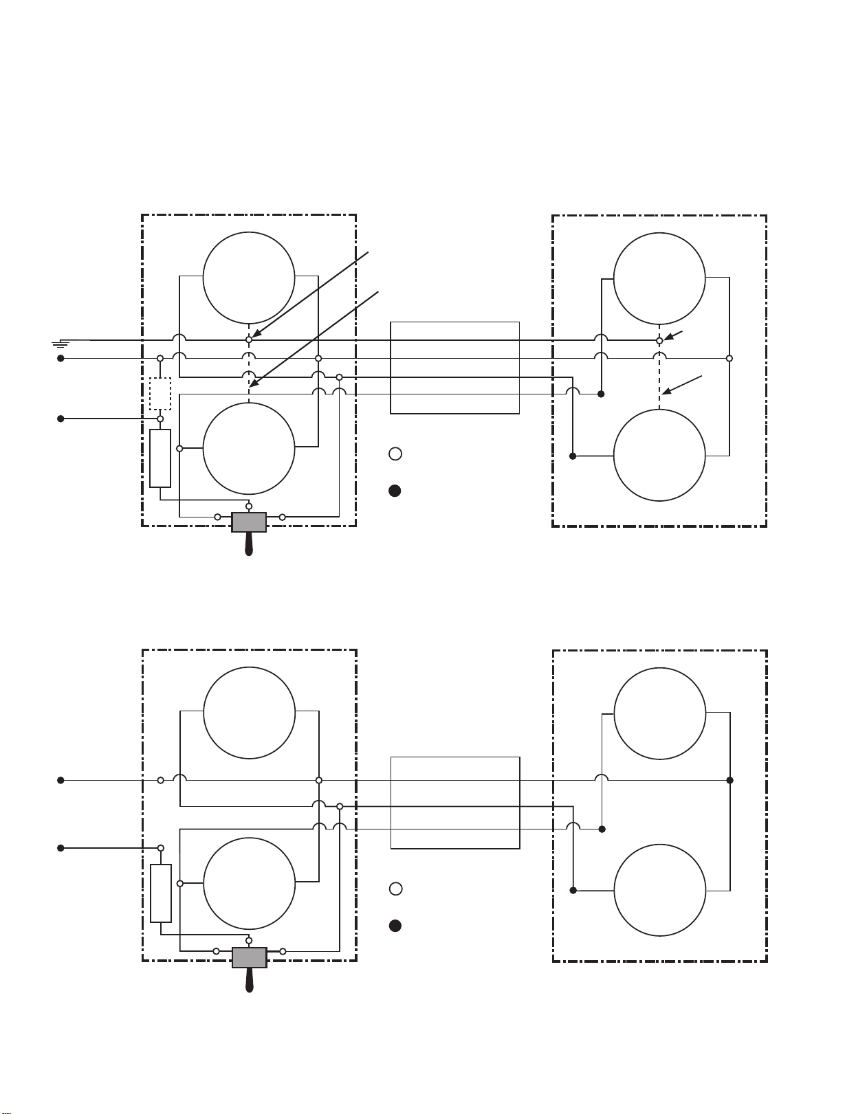
WIRING DIAGRAM for MODELS
SG30-RG (Incandescent) and SG30-RG-LED
[email protected] | t: 1-773-384-7765 | f: 1-773-384-5115 | www.triliteinc.com | Designers and manufacturers of specialty electrical products. Since 1922.
953066 | REV B
SG20-115RG CONTROL UNIT
RED
GREEN
GREEN
(GROUND)
WHITE
(NEUTRAL)
FLASHER
SW = SPDT Switch
Internal Connection
(Do Not Modify)
External Connection
Capacitor
(Incandescent only)
X2
GREEN
WHITE
BLACK
RED
4-Conductor Communication Cable
SG10-115RG DRONE UNIT
RED
GREEN
BLACK
(LABELED ‘GREEN’)
GREEN
WHITE
BLACK
X2 BLACK
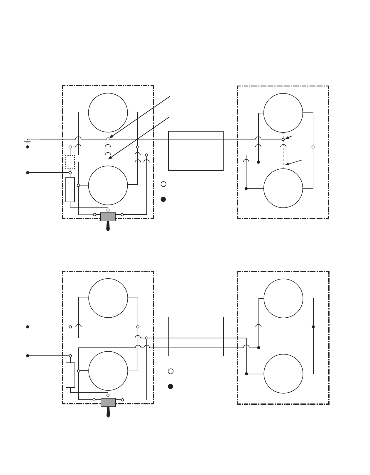
SG20-12RG CONTROL UNIT
SG20-24RG CONTROL UNIT
RED
GREEN
WHITE
(NEUTRAL)
FLASHER
SW = SPDT Switch
Internal Connection
(Do Not Modify)
External Connection
WHITE
BLACK
RED
3-Conductor Communication Cable
RED
GREEN
WHITE
BLACK
SW
SW
SG10-12RG DRONE UNIT
SG10-24RG DRONE UNIT
GROUND
CHASSIS
GROUND
CHASSIS
Incandescent
Only
BLACK
BLACK
(LABELED ‘GREEN’)
This wire used on Incandescent
120 VAC units only
CENTER OFF
CENTER OFF
[email protected] | t: 1-773-384-7765 | f: 1-773-384-5115 | www.triliteinc.com | Designers and manufacturers of specialty electrical products. Since 1922.
953066 | REV B
ROUGE
VERT
VERT
(MASSE)
BLANC
(NEUTRE)
VERT
BLANC
NOIR
ROUGE
Câble de communication à 4 conducteurs
ROUGE
VERT
NOIR
VERT
BLANC
NOIR
X2 NOIR
UNITÉ DE CONTRÔLE SG20-12RG
UNITÉ DE CONTRÔLE SG20-24RG
ROUGE
VERT
BLANC
(NEUTRE)
BLANC
NOIR
ROUGE
ROUGE
VERT
BLANC
NOIR
SW
SW
UNITÉ DRONE SG10-12RG
UNITÉ DRONE SG10-24RG
NOIR
NOIR
Ce l est utilisé uniquement
sur les unités incandescentes
de 120 VCA
HORS TENSION
AU CENTRE
CLIGNOTANT
X2
Connexion interne
(Ne pas modier)
Connexion externe
Condensateur
(Incandescente uniquement)
MASSE DU
CHÂSSIS
(ÉTIQUETÉ «VERT»)
MASSE DU
CHÂSSIS
(Incandescente
uniquement)
SW = COMMUTATEUR SPDT
CLIGNOTANT
(ÉTIQUETÉ «VERT»)
Câble de communication à 3 conducteurs
HORS TENSION
AU CENTRE
SW = COMMUTATEUR SPDT
Connexion interne
(Ne pas modier)
Connexion externe
UNITÉ DE CONTRÔLE SG20-115RG UNITÉ DRONE SG10-115RG
SCHÈMA DE CONNEXION pour les MODÈLES
SG30-RG (Incandescente) et SG30-RG-LED (DEL)
This manual suits for next models
1
Table of contents
Languages:
Other Trilite Safety Equipment manuals


