Spencer FL-X W User manual

SPENCER ITALIA SRLSPENCER ITALIA SRL – Via Provinciale n° 12
43038 Sala Baganza (PR) – Italy
FR
Mode d’emploi
Débitmètres
DE
Gebrauchsanleitung
Flowmeter
EN
Instruction for use
Flowmeters
IT
Istruzioni d’uso
Flussimetri
HU
Használati utasítás
Áramlásmérők
RO
Instrucțiuni de utilizare
Debitmetre
ES
Instrucciones de uso
Flujómetros
PT
Instruções de utilização
Debitómetros
BG
Инструкции за употреба
Дебитомери

2
INDICE / CONTENTS / INHALTSVERZEICHNIS / SOMMAIRE
1. MODELLI 5
2. DESTINAZIONE D’USO 5
2.1 DESTINAZIONE D’USO E BENEFICI CLINICI 5
2.2 PAZIENTI DESTINATARI 5
2.3 CRITERI DI SELEZIONE PAZIENTI 5
2.4 CONTROINDICAZIONI ED EFFETTI COLLATERALI
INDESIDERATI 5
2.5 UTILIZZATORI E INSTALLATORI 5
2.5.1 FORMAZIONE UTILIZZATORI 5
2.5.2 FORMAZIONE INSTALLATORE 5
3. STANDARD DI RIFERIMENTO 5
4. INTRODUZIONE 5
4.1 UTILIZZO DELLE ISTRUZIONI D’USO 5
4.2 ETICHETTATURA E CONTROLLO TRACCIABILITÀ
DEL DISPOSITIVO 5
4.3 SIMBOLI 6
4.4 GARANZIA E ASSISTENZA 6
5. AVVERTENZE 6
6. AVVERTENZE SPECIFICHE 7
7. RISCHIO RESIDUO 7
8. DATI TECNICI E COMPONENTI 7
9. MESSA IN FUNZIONE 8
10. MODALITA’ D’USO 8
10.1 MONTAGGIO UMIDIFICATORE 9
10.2 COLLEGAMENTO ALL’ALIMENTAZIONE 9
10.3 APPLICAZIONE DEL MORSETTO SU BARRA RAIL 9
10.4 UTILIZZO DEL FLUSSIMETRO 10
11. PULIZIA E MANUTENZIONE 10
11.1 PULIZIA 10
11.2 MANUTENZIONE ORDINARIA 10
11.3 REVISIONE PERIODICA 10
11.4 MANUTENZIONE STRAORDINARIA 10
11.5 TEMPO DI VITA 10
12. TABELLA GESTIONE GUASTI 11
13. ACCESSORI 11
14. RICAMBI 11
15. SMALTIMENTO 11
1. MODELS 12
2. INTENDED USE 12
2.1 INTENDED USE AND CLINICAL BENEFITS 12
2.2 TARGET PATIENTS 12
2.3 PATIENT SELECTION CRITERIA 12
2.4 CONTRAINDICATIONS AND SIDE EFFECTS 12
2.5 USERS AND INSTALLERS 12
2.5.1 USER TRAINING 12
2.5.2 INSTALLER TRAINING 12
3. REFERENCE STANDARDS 12
4. INTRODUCTION 12
4.1 USING THE MANUAL 12
4.2 DEVICE LABELLING AND TRACEABILITY 12
4.3 SYMBOLS 13
4.4 WARRANTY AND SERVICE 13
5. WARNINGS/DANGERS 13
6. SPECIFIC WARNINGS 14
7. RESIDUAL RISK 14
8. TECHNICAL DATA AND COMPONENTS 14
9. COMMISSIONING 15
10. OPERATING CHARACTERISTICS 15
10.1 MOUNTING THE HUMIDIFIER 15
10.2 CONNECTION TO THE GAS SUPPLY 16
10.3 APPLICATION OF THE CLAMP ON THE RAIL
BAR 16
10.4 USE OF THE FLOWMETER 16
11. CLEANING AND MAINTENANCE 17
11.1 CLEANING 17
11.2 ROUTINE MAINTENANCE 17
11.3 PERIODIC OVERHAUL 17
11.4 SPECIAL MAINTENANCE 17
11.5 LIFE SPAN 17
12. TROUBLESHOOTING TABLE 17
13. ACCESSORIES 18
14. SPARE PARTS 18
15. DISPOSAL 18
1. MODELLE 19
2. VERWENDUNGSZWECK 19
2.1 VERWENDUNGSZWECK UND KLINISCHER
NUTZEN 19
2.2 ZIELGRUPPE PATIENTEN 19
2.3 KRITERIEN FÜR DIE PATIENTENAUSWAHL 19
2.4 GEGENANZEIGEN UND NEBENWIRKUNGEN 19
2.5 BENUTZER UND MONTEUERE 19
2.5.1 ANWENDERSCHULUNG 19
2.5.2 SCHULUNG FÜR INSTALLATEURE 19
3. NORMVERWEISE 19
4. EINFÜHRUNG 19
4.1 GEBRAUCH DES HANDBUCHS 19
4.2 GERÄTEKENNZEICHNUNG UND
RÜCKVERFOLGBARKEIT 20
4.3 SYMBOLE 20
4.4 GARANTIE UND KUNDENDIENST 20
5. WARNUNGEN/GEFAHREN 20
6. SPEZIELLE WARNUNGEN 21
7. RESTRISIKEN 21
8. TECHNISCHE DATEN UND KOMPONENTEN 22
9. INBETRIEBNAHME 23
10. BETRIEBSEIGENSCHAFTEN 23
10.1 MONTAGE DES BEDEUCHTERS 23
10.2 ANSCHLUSS AN DIE GASVERSORGUNG 23
10.3 ANBRINGUNG DER KLAMMER AN DER
SCHIENE 24
10.4 GEBRAUCH DES FLOWMETERS 24
11. REINIGUNG UND WARTUNG 24
11.1 REINIGUNG 24
11.2 ORDENTLICHE WARTUNG 25
11.3 REGELMÄSSIGE ÜBERHOLUNG 25
11.4 AUSSERORDENTLICHE WARTUNG 25
11.5 LEBENSDAUER 25
12. TABELLE ZUR FEHLERBEHEBUNG 25
13. ZUBEHÖRTEILE 25
14. ERSATZTEILE 25
15. ENTSORGUNG 25
1. MODÈLES 26
2. UTILISATION PRÉVUE 26
2.1 UTILISATION PRÉVUE ET AVANTAGES
CLINIQUES 26
2.2 PATIENTS CIBLE 26
2.3 CRITÈRES DE SÉLECTION DES PATIENTS 26
2.4 CONTRE-INDICATIONSETEFFETS
SECONDAIRES 26
2.5 UTILISATEURS ET INSTALLATEURS 26
2.5.1 FORMATION DES UTILISATEURS 26
2.5.2 FORMATION DES INSTALLATEURS 26
3. NORMES DE RÉFÉRENCE 26
4. INTRODUCTION 26
4.1 UTILISATION DU MANUEL 26
4.2 ÉTIQUETAGE ET TRAÇABILITÉ DES DISPOSITIFS 26
4.3 SYMBOLES 27
4.4 GARANTIE ET SERVICE 27
5. AVERTISSEMENTS/DANGERS 27
DE
FR
EN
IT

12
IT
EN
DE
FR
HU
BG
ES
RO
PT
1. MODELS
The following basic models may be subject to implementation or change without notice.
• FL-X W/HOSE HOLDER • FL-K W/HOSE HOLDER • FL-K W/HUMIDIFIER
• FL-X W/HOSE HOLDER FOR RAIL TUBE 1m • FL-K W/HOSE HOLDER FOR RAIL TUBE 1m • FL-K W/HUMIDIFIER TUBE 1 m
• FL-X W/HUMIDIFIER • FL-K W/HOSE HOLDER TUBE 1 m • FL-X W/HUMIDIFIER FOR RAIL TUBE 1m
• FL-K W/HOSE HOLDER TUBE 2 m • FL-K W/HOSE HOLDER TUBE 3 m
Above mentioned models, are available with connection standard UNI – DIN – AFNOR - BS.
2. INTENDED USE
2.1 INTENDED USE AND CLINICAL BENEFITS
Flowmeters are devices that can be connected directly or through flexible connection groups to terminal units of a medical gas distribution system to which the operator makes
connections and disconnections and are intended for regulating the flow of gas delivered to the patient.
Flowmeters can be used in conjunction with a humidifier which is used to increase the humidity level of the gas delivered to the patient.
2.2 TARGET PATIENTS
There are no particular indications related to the patient group. The product has a wide range of flow settings, making it suitable for different patient needs.
2.3 PATIENT SELECTION CRITERIA
Typical patients, are those for which non-invasive oxygen therapy is required.
2.4 CONTRAINDICATIONS AND SIDE EFFECTS
Prolonged oxygen therapy, without humidification, can cause dryness of patient mucosa. There are no other contraindications known for flowmeters.
2.5 USERS AND INSTALLERS
The intended users are rescue workers with in-depth knowledge related to oxygen administration procedures.
• Personnel trained for use of the device must also have training in monitoring breathing parameters of the patient.
These devices are not intended for lay people.
Flowmeters are devices intended for professional use only. Do not allow untrained persons to help while using the product, as they may cause injury to themselves or
others. Despite all efforts, laboratory tests, trials, and instructions for use, standards do not always reproduce practice, so the results obtained under actual conditions of
product use in the natural environment may sometimes differ significantly. The best instructions are the continuous practice of use under the supervision of competent
and trained personnel.
Operators using the device should be physically able to use the device and have good muscle coordination. Operators’ ability must be assessed before the definition of roles in
use of the stretcher. Operators must be able to provide the necessary patient care.
2.5.1 USER TRAINING
• Regardless of your level of experience with similar devices in the past, you should carefully read and understand the contents of this manual before installing, operating, or
servicing this product. In case of any questions, please contact Spencer Italia S.r.l. for the necessary clarifications.
• The product must be used only by personnel trained in the use of this product and not on other similar products.
• The suitability of the users for use of this product can be attested by the training registration, in which trained persons, trainers, date and place are specified. This docu-
mentation must be kept for at least 10 years after the end of the product’s life and must be made available to the competent authorities and/or the Manufacturer when
requested. In the absence of such documentation, the relevant bodies will apply any foreseen sanctions.
• Do not allow untrained persons to help while using the product, as they may cause injury to themselves or others.
• The product must be put into use only by personnel trained in the use of this product and not on other similar products.
Note: Spencer Italia S.r.l. is always available for training courses.
2.5.2 INSTALLER TRAINING
The device itself does not require installation. It is necessary that those who use the device or make it available to other users, and the users themselves, have adequate training
in relation to the operation of these devices and their connection to the gas supply.
3. REFERENCE STANDARDS
As Distributor or End-User of the products manufactured and/or marketed by Spencer Italia S.r.l., users are strictly required to be familiar with the legal provisions in force in
the country of destination of the goods, applicable to the devices to be supplied (including regulations relating to technical specifications and/or safety requirements) and,
therefore, to understand the requirements necessary to ensure compliance of the products themselves with all legal requirements of the territory.
REFERENCE DOCUMENT TITLE
EU Regulation 2017/745 EU Regulation on Medical Devices
UNI EN ISO 15002 Flow-metering devices for connection to terminal units of medical gas pipeline systems
UNI EN ISO 20789 Anaesthetic and respiratory equipment – Passive humidifiers
4. INTRODUCTION
4.1 USING THE MANUAL
The purpose of this manual is to provide healthcare professionals with the information necessary for safe and appropriate use and maintenance of the device.
Note: The Manual is an integral part of the device and therefore it must be kept for the entire life of the device and must accompany it in any changes of use or ownership. If any
instructions for use for products other than the one received are present, please contact the Manufacturer immediately before use.
Spencer products User Manuals can be downloaded from the site http://support.spencer.it or by contacting the Manufacturer. Exceptions are those items whose essentiality
and reasonable and predictable use are such that it is not necessary to draw up instructions, in addition to the following warnings and indications on the label.
Regardless of your level of experience with similar devices in the past, it is advisable to carefully read and understand the contents of this manual before installing,
operating, or servicing this product.
4.2 DEVICE LABELLING AND TRACEABILITY
Each device is provided with a label, placed on the device itself and/or on the packaging, which contains the Manufacturer’s identification data, product, CE marking, serial
number (SN) or lot number (LOT). This must never be removed or covered.
In the event of damage or removal, request a duplicate from the Manufacturer, or else the warranty will be void as the device can no longer be traced.
If the assigned Lot/SN cannot be traced, the device must be reconditioned, provided only under the responsibility of the manufacturer.
IT
EN
DE
FR
HU
BG
ES
RO
PT
13
EU Regulation 2017/745 requires manufacturers and distributors of medical devices to keep track of their location. If the device is in a location other than the address to which
it was shipped or sold, or if it was donated, lost, stolen, exported or destroyed, permanently removed from use, or if the device was not delivered directly from Spencer Italia
S.r.l., please register the device at http://service.spencer.it, or inform Customer Service (see § 4.4).
4.3 SYMBOLS
Symbol Meaning Symbol Meaning
Device in compliance with EU Regulation 2017/745 Use no oil
Medical device Oxygen
Manufacturer Maximum input pressure
Date of manufacture Reading point
See the user manual. Lot number
Temperature limit – Indicates allowed temperature limit Product code
Mandatory to read instructions for use
(01)08057711230006 (11) 200626 (10) 1234567890
Production identification
Alphanumeric code that identifies the production units of the device,
composed of:
(01)805771123 company prefix
000 progressive GS1
6 control number
(11)200626 date of production (YYMMDD)
(10)1234567890 lot/SN
4.4 WARRANTY AND SERVICE
Spencer Italia S.r.l. guarantees that products are free from defects for a period of one year from the date of purchase.
For information regarding correct interpretation of the instructions for use, maintenance, installation or return, please contact Spencer Customer Service tel. +39 0521 541154,
fax +39 0521 541222, e-mail service@spencer.it.
To facilitate service, always indicate the lot number (LOT) or serial number (SN) on the label attached to the package or device itself.
Warranty and service conditions are available at http://support.spencer.it.
Note: Record and keep with these instructions: lot (LOT) or serial number (SN), if present, place and date of purchase, date of first use, date of checks, user name and comments.
To ensure the traceability of the products and protect maintenance and service procedures on your devices, Spencer has made the SPENCER SERVICE portal (http://service.
spencer.it/ ) available to you. From this site, you can view the data of the products in your possession or placed on the market, monitor and update schedules for periodic
checks and view and manage special maintenance.
5. WARNINGS/DANGERS
Warnings, dangers, notes, and other important safety information are provided in this section and are clearly visible throughout the manual.
Product features
Use of the product for any purpose other than that described in the User Manual is prohibited.
• Before each use, always check the conditions of the product, as specified in the User Manual. In the event of faults/damage that could compromise its functionality/safety,
immediately remove it from service and contact the Manufacturer.
• If the product is found to be malfunctioning, immediately use a similar device to ensure continuity of ongoing operations. Non-compliant devices must be taken out of
service.
• The product must not be tampered with or modified without the manufacturer’s authorisation (modification, tweaking, additions, repair, use of non-approved accessories),
as they may constitute imminent danger of injury to persons and material damage. Should these operations be performed, we decline any responsibility for incorrect ope-
ration or any damage caused by the product itself; moreover, the CE marking and the product warranty shall be null and void.
• Be sure to take every precaution to avoid hazards from contact with blood or body secretions, if applicable.
• Avoid contact with sharp or abrasive objects.
Storage
• The product must not be exposed or come into contact with thermal sources of combustion or flammable agents, but must instead be stored in a dry, cool place, away
from light and sun.
• Do not store the product under other more or less heavy materials that may damage the product.
• Store and transport the product with its original packaging, otherwise the warranty shall be invalidated.
Regulatory requirements:
As Distributor or End-User of the products manufactured and/or marketed by Spencer Italia S.r.l., users are strictly required to be familiar with the legal provisions in force in
the country of destination of the goods, applicable to the devices to be supplied (including regulations relating to technical specifications and/or safety requirements) and,
therefore, to understand the requirements necessary to ensure compliance of the products themselves with all legal requirements of the territory.
• Promptly and in detail notify Spencer Italia S.r.l. (already in the quotation request phase) about possible fulfilments by the Manufacturer necessary for the compliance of
products with specific legal requirements of the territory (including those deriving from regulations and/or regulatory provisions of another nature).
• Act with due care and diligence to help ensure compliance with the general safety requirements of the devices placed on the market, providing end-users with all the infor-
mation necessary to carry out periodic revisions on the supplied devices, exactly as indicated in the User Manual.
• Participate in safety checks on products placed on the market, transmitting information regarding product risks to the Manufacturer as well as to the Competent Authorities
fortheirrespectiveactions.
• Without prejudice to the above, the Distributor or End-User shall assume wider liability related to non-compliance with non-fulfilment of the above-mentioned obligations,
with consequent obligation to indemnify and/or hold Spencer Italia S.r.l. harmless from any possible injurious effect.
• With reference to EU Regulation 2017/745, please note that public or private operators who, when exercising their activity, detect an incident involving a medical product
are required to notify the Ministry of Health, within the terms and in the manner established by one or more ministerial decrees, and notify the Manufacturer. Public or
private health care professionals are required to notify the Manufacturer of any other incident that may allow the adoption of measures to ensure the protection and health
of patients and users.

14
IT
EN
DE
FR
HU
BG
ES
RO
PT
General warnings for medical devices
The user must carefully read the following in addition to the general warnings.
• Qualified personnel must be present during use of the device.
• Do not use if the device or parts of it are punctured, torn, frayed, or excessively worn.
• Follow the internal procedures and protocols approved by your organisation.
• Do not alter or modify the device arbitrarily, as doing so could result in unpredictable operation and damage to the patient or rescuers and shall void the manufacturer’s
warranty and release the manufacturer from all liability.
6. SPECIFIC WARNINGS
To use the device, you must also have read, understood and carefully follow all the instructions in the user manual.
• Before commissioning, check that the device has not been contaminated with lubricants. In that case, do not use it.
• Do not lubricate any part of the flowmeter as it is not required and could cause a fire or explosion hazard.
• Be careful when disconnecting the flow meter from the gas distribution line, as the pressure could cause the probe to be ejected upon release, with consequent damage
to the operator.
• Variations in inlet pressure, output resistance and ambient temperature can affect flow accuracy.
• When setting a flow value on the FL-K model, make sure that the knob is correctly positioned on the desired flow value and not between adjacent values, as the output flow
may not correspond to the desired one and the selector may move to higher or lower flow settings.
• The FL-K flowmeter, unlike the FL-X, does not provide any indication of the presence of a flow. Before starting therapy, verify that the device is properly supplied and that
the gas is coming out from the patient connection port.
• Always close the flow adjustment valve or put the selector in position “0” both when the device is not in use and when connections and disconnections from the gas
distribution line have to be made.
• Attention: The flow meter does not act as a shut-off valve. To avoid unwanted losses of unwanted oxygen, always close the main system tap (or the cylinder valve)
• Make sure that only medical oxygen is used, contained in cylinders in compliance with the directives in force and adequately identified. The use of non-compliant gas sources
could seriously compromise the safety of the device.
• Do not use the device in the presence of open flames or near heat sources.
• Any maintenance operation must be carried out with the device disconnected from the pneumatic power supply.
• The humidifier must be filled with distilled water, in order to limit the formation of deposits that could make the flow meter not working.
• Establish a maintenance program and periodic checks, identifying a reference employee. The person entrusted with routine maintenance of the device must ensure the basic
requirements set by the manufacturer, within these instructions for use
• Do not use the device in conjunction with other equipment not expressly approved by the manufacturer.
• Before each use, always check the integrity of the device, as specified in the instructions for use. In the event of anomalies or damage that may compromise the functionality
and safety of the device, therefore of the patient and the operator, it is necessary to replace the damaged parts.
• The device is intended to be applied to a medical gas distribution line through the specific gas coupling. Its normal use does not require the device to be moved from one
place to another for use on the patient, but that it is used only if connected to a distribution line for the administration of medical oxygen.
• Make sure that the physician has carried out the necessary primary assessments.
• The device provides oxygen to the patient’s airways. Be careful to not contaminate the humidifier or flowmeter, as residual contaminants could reach the patient.
7. RESIDUAL RISK
No residual risks, or rather risks that could arise despite compliance with all warnings in this user manual, have been identified.
8. TECHNICAL DATA AND COMPONENTS
Note: Spencer Italia S.r.l. reserves the right to make changes to specifications without notice.
FL-K
7
4
5
6
2
3
1
8
9
10
DESCRIPTION AND MATERIAL
1
Adjustment knob
Made of aluminum, it allows the regulation of the flow on pre-set
values.
2
Reading point
By turning the adjustment knob, in this point it is possible to read the
set flow. The flow is also readable on the upper side of the flowmeter
3
Humidifier patient connection port
Aluminum hose connector applied to the humidifier, to which shall be
connected a hose in compliance with ISO 13544-2.
4
Humidifier container
Polycarbonate container in which to put distilled water intended for
nebulization
5
Bubbler
Made of PE, it is immersed in liquid. The oxygen that passes through
the bubbler is humidified by passing through the water
6
Humidifier cap
Made of ABS, it closes the humidifier and is part of the connection
with the flow meter
7
Probe
Gas specific component that allows connection to a gas specific outlet
on a gas delivery system
8
Connection tube
Made of PVC, it is used in the models designed for application to a
clamp. The tube is equipped with a specific gas coupling
9
Equipment support
Made of aluminum, it is the component needed to apply the
flowmeter to the clamp
10
Flowmeter patient connection port
Aluminum hose holder applied on the flowmeter at which a tube in
compliance with ISO 13544-2 shall be applied

IT
EN
DE
FR
HU
BG
ES
RO
PT
15
FL-X
8
9
10
DESCRIPTION AND MATERIAL
1
Reading column
Ruotando la manopola di regolazione, una sfera all’interno della
colonnina in policarbonato, indica il valore istantaneo di flusso
2Adjustment knob
Made of aluminum, it allows flow regulation
3
Humidifier patient connection port
Aluminum hose connector applied to the humidifier, to which a hose
conforming to ISO 13544-2 is connected.
4
Humidifier container
Polycarbonate container to be filled with distilled water intended for
nebulization
5
Bubbler
Made of PE, it is immersed in liquid. The oxygen that passes through
the bubbler is humidified by passing through the water
6
Humidifier cap
Made of ABS, it closes the humidifier and is part of the connection
with the flow meter
7
Probe
Gas specific component that allows connection to a gas specific outlet
on a gas delivery system
8
Connection tube
Made of PVC, it is used in the models designed for application to a
clamp. The tube is equipped with a specific gas coupling
9
Equipment support
Made of aluminum, it is the component needed to apply the
flowmeter to the clamp
10
Flowmeter patient connection port
Aluminum hose holder applied on the flowmeter at which a tube in
compliance with ISO 13544-2 shall be applied
TECHNICAL DATA
Intended gas Oxygen
Input pressure range From 400 to 500kPa
P1 – Maximum input pressure 500kPa
Flow adjustment FL-K Step: 0 - 0,5 – 1 – 2 – 3 – 4 – 5 – 6 – 8 – 10 – 12 – 15
Flow adjustment FL-X Continuous from 0 to 15 L/min
Humidifier maximum input flow 20 l/min
Humidifier allowed temperature range from +5 to +40°C
Water volume available for nebulization 60 ml
Nebulization time between refills ~4h @ 15l/min
Humidification output ~ 10±2mg/l@ 15l/min
9. COMMISSIONING
For first use, check that:
• Packaging is intact and has protected the device during transportation
• Check that all parts included in the packing list are present.
• General functionality of the device
• Product cleanliness - contamination with lubricants can cause combustion
• Verificare che la linea di distribuzione abbia le prestazioni necessarie a garantire il corretto funzionamento del dispositivo.
Do not modify the device or its parts for any reason as this could cause damage to the patient and/or rescuers.
Failure to take the above measures will preclude safe use of the device, resulting in risk of damage to the patient, operators and the device itself.
If the above conditions are met, the device may be considered ready for use; otherwise, you must immediately remove the device from service and contact the Manufacturer.
Do not alter or modify the device arbitrarily, as doing so could result in unpredictable operation and damage to the patient or rescuers and will void the warranty and
release the Manufacturer from all liability.
10. OPERATING CHARACTERISTICS
The need for oxygen therapy must be assessed by a doctor or, if allowed by local regulations, by a nurse.
The practice is intended to increase the patient’s oxygen concentration.
In the case of a patient who is unconscious or unable to breathe spontaneously, it is necessary to use more advanced ventilation devices.
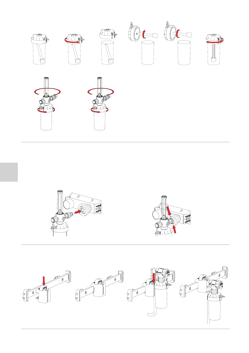
10.1 MOUNTING THE HUMIDIFIER
If the model is equipped with it, before using the device, it is necessary to mount the humidifier bubbler and the humidifier to the flow meter.
To assemble the bubbler, open the humidifier cap and screw the bubbler to the cap. The operation is illustrated in the following images.
16
IT
EN
DE
FR
HU
BG
ES
RO
PT
To screw the humidifier to the flow meter, screw them together, keeping the grip firmly to avoid accidental falls that could damage the devices.
On the humidifier canister, there are the markings of the maximum and minimum
water levels. When the device is put into service, it will be necessary to unscrew the
jar from the cap, fill it with distilled water up to the level indicated with MAX, then
screw again the canister.
Do not leave water in the humidifier when not in use to avoid encrustation as well as
aging with consequent bacterial proliferation of the liquid.
10.2 CONNECTION TO THE GAS SUPPLY
Flowmeters are equipped with a gas specific probe of the standard requested from the customer upon those available. Such probes, can be connected to a female terminal
unit of the same standard and intended for the same gas.
Make sure, before commissioning the device, that the terminal unit to which you want to connect the device complies with the relevant regulations both in terms of
performance and connection standards. The target gas and the maximum operating pressure are marked on the device.
Turn the flow adjustment knob to the closed position.
The connection to the terminal unit takes place simply by inserting the coupling present on the flow meter or on the connection pipe, in the female terminal unit available in
the gas distribution system.
Press until you feel the coupling between the parts.
The flow meter, in all its versions, must always be used in a vertical position.
To disconnect the device from the terminal unit, press on the ring nut of the same.
ATTENTION: Risk of injury - the gas pressure could cause violent ejection of the graft. Make sure you have a firm grip on the device.
10.3 APPLICATION OF THE CLAMP ON THE RAIL BAR
If your product is equipped with the equipment support, intended for application on a rail bar clamp, proceed as follows:
1 – Press the button on the upper part of the clamp to open the clamp.
2 – Position the clamp on the rail bar in the desired position and release the button previously pressed.
3 – Insert the aluminum support inside the guide of the clamp until you feel it has hooked.
4 – Connect the coupling at the end of the tube to the terminal unit as already described in the previous paragraph.
10.4 USE OF THE FLOWMETER
Both FL-X and FL-K are equipped with a knob that allows adjustment of the output flow. FL-K allows you to set the flow at the “steps” indicated in the paragraph relating to

IT
EN
DE
FR
HU
BG
ES
RO
PT
17
technical data, while FL-X allows continuous adjustment of the flow which is shown on the graduated column on which it is possible to read the set flow.
The increase in flow, by regulatory convention, takes place counterclockwise.
The direction of this increase is symbolized on the devices themselves.
Connect to the patient connection port an oxygen therapy tube compliant with ISO 13544-2 fitting to the patient connection port ( i.e. the hose connector on the flow meter
or humidifier if fitted to your model), and apply it to an oxygen therapy mask of adequate size for the patient .
The use of non-compliant hoses could cause loss of performance and prevent the expected performance of the therapy.
Fill the humidifier with distilled water as previously described then, after defining the flow value based on the patient’s needs, set the relative value and start therapy.
If refill of the humidifier is needed, consider that when the humidifier canister is opened, the therapy is interrupted.
ATTENTION: The use of liquids other than distilled water or the addition of additives may have undesirable effects related to the administration of this substance.
ATTENTION: Do not use the humidifier outside the approved environmental ranges
ATTENTION: This humidifier is not suitable for patients whose upper respiratory tract has been bypassed via an endotracheal tube. It does not provide sufficient humidification
to prevent irritation and dryness of the mucous membranes of the lower tract.
After use, disconnect the flow meter from the terminal unit and empty the humidifier if your model is equipped with it.
Proceed with cleaning as indicated in the following paragraph.
11. CLEANING AND MAINTENANCE
11.1 CLEANING
Failure to carry out the correct cleaning operations could increase the risk of cross-infection due to presence of body fluids and/or residues.
The operator must wear suitable personal protective equipment, such as gloves, goggles, etc. during all checking and cleaning operations.
Wash the exposed parts with a soft cotton cloth moistened with warm water and neutral soap; never use solvents or stain removers.
Remove any residues with an additional cotton cloth moistened with warm water.
Leave to dry naturally.
The humidifier can be washed with water and neutral soap. Carry out several rinses alternately with warm water and cold water.
Leave to dry naturally.
Do not immerse in disinfectants .
Do not autoclave.
Do not use flammable products.
11.2 ROUTINE MAINTENANCE
You must establish a maintenance program and periodic checks, identifying a designated reference person. The person entrusted with device maintenance must ensure
the basic requirements envisaged within this user manual.
All routine and special maintenance activities and all general overhauls must be recorded and documented with the relevant technical intervention reports. This
documentation must be kept for at least 10 years after the end of the device’s life and must be made available to the competent authorities and/or the Manufacturer
when requested.
The operator must wear suitable personal protective equipment, such as gloves, goggles, etc. during all checking, maintenance and cleaning operations.
The maintenance schedule must comply with the following table:
Minimum maintenance intervals At each use If necessary Every month
Cleaning ●
Check of the connection to the terminal unit ●
Inspection ● ● ●
The inspection to be carried out after each use consists of:
• Check that all components are present
• Check of the integrity of the device – There must be no breaks, holes or cuts
• Check the state of wear - There must not be a level of abrasion such as to compromise the legibility of the marking and the safety of the product.
• Check the state of wear of each component in general
• Check that all the accessories provided are present, functional and intact
Use only original or Spencer Italia S.r.l. approved components/replacement parts and/or accessories to carry out any operation without causing alterations or modifications
to the device. Otherwise, we decline all responsibility regarding incorrect operation or any damage caused by the device to the patient or the operator, invalidating the
warranty and invalidating compliance with EU Regulation 2017/745.
11.3 PERIODIC OVERHAUL
No periodic overhaul is foreseen for the device.
11.4 SPECIAL MAINTENANCE
Special maintenance can only be carried out by the Manufacturer, who uses internal and external technicians specialised and authorised by the Manufacturer itself.
Only maintenance activities carried out by specialised technicians authorised by the Manufacturer are considered valid by Spencer Italia S.r.l..
11.5 LIFE SPAN
The device, if used as described in the following instructions, has an average life span of 2 years from the date of purchase.
Spencer Italia S.r.l. will accept no responsibility for incorrect operation or damage caused by the use of devices that have exceeded the maximum allowable life span.
12. TROUBLESHOOTING TABLE
PROBLEM CAUSE REMEDY
Leaks Worn o-rings or insufficient tightening of components
Verify that the flow regulating valve is in closed position.
Check that the coupling with the terminal unit is effective.
If the problem persists, take the device out of service and contact the
manufacturer.
Inadequate performances
Internal channels or filter is blocked due to contamination
coming from oxygen cylinders Put the device out of service and contact the manufacturer
Damage to sealing components

18
IT
EN
DE
FR
HU
BG
ES
RO
PT
Notice
The information in this manual is subject to change without notice. The images are included as examples and may vary slightly from the actual device.
© Copyright Spencer Italia S.r.l.
All rights reserved. No part of the document may be photocopied, reproduced or translated into another language without prior written consent from Spencer Italia S.r.l.
13. ACCESSORIES
There are no accessories available for this device.
14. SPARE PARTS
RIFL002C HOSE HOLDER FL-X RIFL004 HUMIDIFIER
RIFL003 HOSE HOLDER FL-K
15. DISPOSAL
When devices and their accessories are no longer suitable for use, they can be disposed of as normal municipal solid waste if they have not been contaminated by special
agents. Otherwise, follow the regulations in force regarding disposal.

spencer.it | support.spencer.it - e-mail: info@spencer.it | service: service@spencer.it
Ph./Tel. +39.0521.541111
Quality System EN ISO 9001 – EN ISO 13485
Prima emissione: 22/06/2022
Rev. 1 22/06/2022
Codice CCI5332
First issue: 20/06/2022
Rev. 1 20/06/2022
Code CCI5332
Erste Ausgabe: 20/06/2022
Rev. 1 20/06/2022
Code CCI5332
Premièreémission : 20/06/2022
Rév. 1 20/06/2022
Code CCI5332
Primera publicación: 20/06/2022
Rev. 1 20/06/2022
Código CCI5332
Primeira versão: 20/06/2022
Rev. 1 20/06/2022
Código CCI5332
Elsőkiadás: 2022/06/20
Fel. 1 2022/06/20
Kód CCI5332
Първоиздание: 20/06/2022г.
Ред.1 20/06/2022г.
Код CCI5332
Primaediție 20/06/2022
Rev. 1 20/06/2022
Cod CCI5332
This manual suits for next models
1
Table of contents


