JENCO VisionPlus EC 330 User manual

Operation Manual
MODEL EC 330
Microcomputer Based
Conductivity /TDS
&Temperature Pocket
Meter
EC330

1
CONTENTS
INITIAL INSPECTION AND ASSEMBLY .....................2
VISIONPLUS EC 330 OVERVIEW................................2
A. Meter Description..................................................2
B. LCD Display ..........................................................2
OPERATION MODES AND KEYPAD OPERATIONS...3
A. Operation Modes.....................................................3
B. Keypad Operations...............................................3
BEFORE YOUR FIRST USE ..........................…………4
A. Insert Batteries ...........................................4
B. Soak the Electrode.... ..........................................4
C. Preparing Standard Solutions.................................4
D. Setup and Calibrate the Electrode and Meter...........5
USING VISIONPLUS EC 330........................................5
A. Power on/off ......................................................5
B. Calibrate Conductivity............................................5
C. Measure ..............................................................6
D. Hold Data ...........................................................6
REPLACE ELECTRODE…...........................................6
REPLACE THE OLD BATTERIES................................7
ERROR DISPLAYS AND TROUBLESHOOTING …....8
SPECIFICATIONS ......................................................9
WARRANTY ...............................................................10

2
INITIAL INSPECTION AND ASSEMBLY
Carefully unpack the instrument and accessories. Inspect for
damages made in shipment. If any damage is found, notify your
Jenco representative immediately. All packing materials should
be saved until satisfactory operation is confirmed.
VISIONPLUS EC 330 OVERVIEW
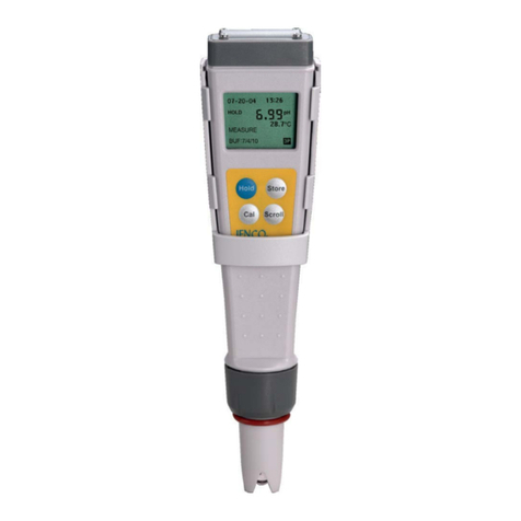
A. Meter Description
1. Battery cap
2. LCD screen
3. Keypad
4. Electrode collar
5. Electrode & ATC assembly
(Electrode cap is not shown.)
B. LCD Display
1
2
3
4
5
6
7
8
9
1. LOW BATTERY indicator
2. CALIBRATION mode indicator
3. MEASURE mode indicator
4. HOLD mode indicator
Hold
Cal Mode
R
EC 330
VisionPlus
1
2
3
4
5

3
5. CONDUCTIVITY/TDS mode indicator
6. CONDUCTIVITY/TDS unit indicator
7. CONDUCTIVITY/TDS reading
8. TEMPERATURE reading
9. TEMPERATURE unit indicator
OPERATION MODES AND KEYPAD OPERATIONS
A. Operation Modes
VisionPlus EC 330 meter has 3 operation modes:
1. Measure Mode. Measure Mode is used to make all
conductivity or TDS and temperature measurements.
2. Calibration Mode. Calibration Mode is used to perform
1 or 2 point calibration.
3. Hold Mode. Hold Mode is used to display the locked
reading for increased ease of use.
B. Keypad Operations
Key
Operation
Mode
Duration
Function
Hold
Measure
0 second
Holds current
measurement reading.
Press again to resume
measuring.
Hold
0 second
Returns to Measure Mode.
Measure
5 second
. Erases all stored data.
Cal
Measure
0 second
Enters Calibration Mode.
On/Off
All
0 second
Turns meter on/off.
Mode
Measure
0 second
Selects display mode:
conductivity (℃),
conductivity (℉),TDS(℃)
and TDS(℉).

4
BEFORE YOUR FIRST USE
A. Insert Batteries
1. Remove the battery cover
at the top of the unit.
2. Insert the set of batteries
(included) ensuring correct
polarities.
3. Securely replace battery
cover.
B. Soak the Electrode
1. Remove the electrode cap covering the VisionPlus EC 330
meter.
2. Soak the electrode in distilled water for 10 minutes before
first use or after storage.
C. Preparing Standard Solutions
Suitable conductivity standards are available commercially or the
user can prepare them using research grade reagents.
Here are some standard solutions the user can prepare to
calibrate the probe of the model EC330.
1. Standard solution of 1413uS at 25℃: Accurately weight out
0.746 grams of research grade dried Potassium Chloride
(KCL). Dissolve in 1000ml of distilled water.
2. Standard solution of 12.90mS at 25 ℃: Accurately weight
out 7.4365 grams of research grade dried Potassium
Chloride (KCL). Dissolve in 1000ml of distilled water.
[Note: You can store the remaining solution in a plastic container
for one week but the air space between the cap and the solution
must be kept to an absolute minimum. Storing the excess solution
below 4℃can increase the storage life. If you have any doubt of
the accuracy of the stored solution, a fresh batch should be
prepared.]
12

5
D. Setup and Calibrate the Electrode and Meter
VisionPlus EC 330 must be setup and calibrated before your
first use. Please follow the instructions detailed in section
USING VISIONPLUS EC 330 6.
USING VISIONPLUS EC 330
A. Power On/Off
Press the “On/Off ” key to turn the unit on. If the unit is running
then you can press the ”On/Off “ key to turn the unit off. The unit
will automatically turn off after 10 minutes of no key activity.
[Note: The unit will not automatically shut off if it is still immersed
in solution even after 10 minute of no key activity.]
B. Calibrate Conductivity
The user can select one or two point conductivity calibration.
1. Rinse the electrode & ATC assembly in distilled water and
immerse them in the standard solution of 1413uS. The
temperature displayed is the solution temperature.
2. Press “Cal” key to initiate calibration. The “CAL” icon will
appear when the main display shows “1415”. Single
Point calibration is now complete. The “MEAS” icon will
appear. The unit is now ready to measure.
[Note: At this moment, the unit can measure 0~2000uS
range of conductivity.]
3. Remove the electrode & ATC assembly from the standard
solution of 1413uS. Rinse them in distilled water and
immerse them in the standard solution of 12.90mS. The
unit will display the temperature of the standard solution
of 12.90mS.
4. Press “Cal” key to initiate calibration. The “CAL” icon will
appear when the main display shows “12.90”. Dual
Points calibration is now complete. The “MEAS” icon will
appear. The unit is now ready to measure.
[Note: At this moment, the unit can measure
0.0~20.00mS range of conductivity. ]

6
C. Measure
In the “Measure Mode”, dip the meter into the test solution.
Measuring for Conductivity (℃) commences. Press “Mode” key to
select: Conductivity(℃), Conductivity(℉), TDS(℃) and TDS(℉).
[Note: If the “CAL” icon does not appear, during measuring, it
means the unit has not been calibrated. Repeat the calibration
procedure.]
D. Hold Data
1. When the conductivity reading is stable, press “Hold” key
once to lock the reading.
2. Press “Hold” key again to unlock reading and the unit will
return to “Measure Mode”. The unit is now ready for
another measurement.
REPLACE ELECTRODE
1. Unscrew the electrode collar to remove the electrode &
ATC assembly as shown in the right figure.
2. Remove the old electrode from
the electrode collar.
3. Insert a new electrode, make
sure the electrode fit back into
the meter correctly.
4. Screw back the electrode collar.
5. Soak the electrode in distilled water for 10 minutes and
recalibrate the EC 330 following the instructions detailed
in section USING VISIONPLUS EC 330..

7
REPLACE THE OLD BATTERIES
Replace the battery when the blinking low battery indicator “ ”
appears on the upper left corner of the LCD screen. The instrument
can operate within specifications for approximately 2~3 hours after
low battery indicator appears.
1. Take off the battery cover.
2. Remove all of the old batteries and insert a new set of
batteries ensuring the polarities are correct.
[Note: Calibration of the unit is required after replacement of
batteries.]

8
ERROR DISPLAYS AND TROUBLESHOOTING
Conductivity
LCD Display
ATC
Display
y
DISPLAY
Mode
Possible cause(s)
[Action(s)]
"OVER"
"OVER"
Measure
Temperature >99.9°
C range.
[Bring solution to a
lower temperature.]
[Replace electrode
& ATC assembly .]
"OVER"
"udr"
Measure
Temperature <0.0°C
range.
[Bring solution to a
higher temperature.]
[Replace electrode
& ATC assembly .]
"OVER"
60.0 ~ 99.5°C
Measure
Temperature
>60.0°C, over the
temperature
compensation range.
[Bring solution to a
lower temperature.]
"OVER"
0.0 ~ 60.0°C
Measure
[The conductivity
value of the test
solution is beyond
20mS.]
[Replace electrode &
ATC assembly.]
"ERR"
/
Calibration
a.Temperature
exceed 0 ~ 60.0°C
Temperature
compensation
b. Correction of
slope beyond
50%.
[Bring solution to a
lower temperature.]
[Use a new
standard solution.]
[Replace electrode &
ATC assembly.]

9
SPECIFICATIONS
Conductivity
Range
Resolution
Accuracy
0 to 20.00 mS/cm
5 uS/cm (40~2000 uS/cm)
±1% F.S.
0.05 mS/cm (2.00 ~ 15.00 mS/cm)
0.10 mS/cm (15.00 ~ 20.00 mS/cm)
TDS
Range
Resolution
Accuracy
0.00 to 10.00 g/L
5 mg/L (20 ~ 1000 mg/L)
±1% F.S.
0.05 g/L (1.00 ~ 7.50 g/L)
0.10 g/L (7.50 ~ 10.00 g/L)
Temperature
Range
Resolution
Accuracy
0.0 to 99.5 °C
32 to 212 °F
0.5 °C
1 °F
±0.5 °C
±1 °F
Conductivity
Temperature compensation
Temperature Coefficient
Reference temperature
AUTO 0.0 °C to 60.0 °C
1.91 %/°C
25 °C
TDS
TDS Constant 0.50
Temperature
Temperature sensor Thermistor, 10 k
Ω
at 25 °C
Temperature unit °C and °F
General
Power: LR44 x 4
Battery life: >100 Hours
Ambient temperature range 0.0 to 50.0 °C
Case IP67 water-tight case
Weight 105 g

10
WARRANTY
Jenco warrants this product to be free from significant
deviations in material and workmanship for a period of 1 year
from date of purchase. If repair or adjustment is necessary and
has not been the result of abuse or misuse, within the year
period, please return-freight-prepaid and the correction of the
defect will be made free of charge. If you purchased the item
from our Jenco distributors and it is under warranty, please
contact them to notify us of the situation. Jenco Service
Department alone will determine if the product problem is due to
deviations or customer misuse.
Out-of-warranty products will be repaired on a charge basis.
RETURN OF ITEMS
Authorization must be obtained from one of our representatives
before returning items for any reason. When applying for
authorization, have the model and serial number handy,
including data regarding the reason for return. For your
protection, items must be carefully packed to prevent damage in
shipment and insured against possible damage or loss. Jenco
will not be responsible for damage resulting from careless or
insufficient packing. A fee will be charged on all authorized
returns.
NOTE: Jenco reserves the right to make improvements in
design, construction and appearance of our products without
notice.

11
Jenco Instruments, Inc.
7968 Arjons Drive, Suite C
San Diego, CA 92126 USA
TEL: 858-578-2828
FAX: 858-578-2886
Website: www.jencoi.com
Jenco Electronics, Ltd.
6F., NO. 81, Sec.2, Chang-an E. Rd., Jhongshan District, Taipei
City 104, Taiwan
TEL: 886-2-2508-2928
FAX: 886-2-2508-2938
E-Mail: [email protected]
Website: www.JENCO.com.tw
Shanghai Jenco Instruments, Ltd.
18 Wang Dong Zhong Road
Sijing Town, Songjiang
Shanghai, China
TEL: 86-021-5761-9599
FAX: 86-021-5761-9598
E-Mail: [email protected]
Website: www.jenco.com.cn
Table of contents
Other JENCO Measuring Instrument manuals

JENCO
JENCO VisionPlus pH630 User manual

JENCO
JENCO VisionPlus 6177 User manual

JENCO
JENCO 6360 User manual

JENCO
JENCO 6250 User manual

JENCO
JENCO VisionPlus pH6810 User manual

JENCO
JENCO 3020M User manual

JENCO
JENCO 3173 User manual
JENCO
JENCO 6177M User manual

JENCO
JENCO 3177MB User manual

JENCO
JENCO 6377MB User manual

JENCO
JENCO 6230M User manual

JENCO
JENCO VisionPlus pH618N User manual

JENCO
JENCO VisionPlus 9020M User manual

JENCO
JENCO 3011M User manual
JENCO
JENCO 6308CST User manual

JENCO
JENCO pH619 Installation manual

JENCO
JENCO VisionPlus pH618N User manual

JENCO
JENCO 6179MB User manual

JENCO
JENCO 6179 User manual
JENCO
JENCO VisionPlus pH630FA User manual