BYK micro-TRI-gloss ? User manual

Additives & Instruments
A member of
micro-TRI-gloss μ
Measure what you see.
Operating Instructions
Betriebsanleitung
Mode d’emploi

1
English
micro-TRI-gloss Operating instructions
Betriebsanleitung
Mode d’emploi
Patent pending
Patent angemeldet
Demande de brevet en cours
Deutsch
Français
260 017 521 EDF 0401

%NGLISH
"9+¬¬'ARDNER¬'MB(
,AUSITZER¬3TRAE¬
$¬¬¬'ERETSRIED
'ERMANY
4EL¬ GARDNER
¬ ¬
¬ ¬
&AX¬ ¬
"9+¬¬'ARDNER¬53!
¬'UILFORD¬2OAD
#OLUMBIA¬-$¬
53!
0HONE¬ ¬
¬
&AX¬
¬ ¬
¬
WWWBYKCOMINSTRUMENTS

3
English
Table of contents
1 Description of the system 6
2 Safety instructions 7
3 General Information 9
4 Commissioning and power supply 10
5 Control elements 12
6 Getting started 14
7 Overview of main menu 18
8 Mode and sample measurement 19
9 Statistics 20
10 Continuous 25
11 Basic mode 26
12 Geometry / Sensor 27
13 Save 30
14 Difference measurement and Pass/Fail 34
15 Calibration and Autodiagnosis 40
16 Setup 48
17 Practical measuring suggestions 50
18 Standards 53
19 Interface 54
20 Technical data 55
21 Delivery notes 57
22 Errors and warning messages 58
Specifications subject to change without notice

4
English
Inhaltsverzeichnis
1 Systembeschreibung 60
2 Sicherheitshinweise 61
3 Allgemeine Hinweise 63
4 Inbetriebnahme und Energieversorgung 64
5 Bedienelemente 66
6 Erste Schritte 68
7 Übersicht Hauptmenü 72
8 Messmodus und Einzelmessung 73
9 Statistik 74
10 Dauermessung 79
11 Basismodus 80
12 Geometrie / Sensor 81
13 Speicherung 84
14 Differenzmessung und Pass/Fail 88
15 Kalibration und Autodiagnose 94
16 Setup 102
17 Messpraxis 104
18 Normen 107
19 Schnittstelle 108
20 Technische Daten 109
21 Lieferhinweise 111
22 Fehler und Warnhinweise 112
Technische Änderungen vorbehalten

5
English
Sommaire
1 Principe 114
2 Consignes de sécurité 115
3 Informations Générales 117
4 Mise en service et alimentation en énergie 118
5 Éléments de commande 120
6 Premières étapes 122
7 Aperçu Menu principal 126
8 Modes mesurage et échantillon 127
9 Mode statistique 128
10 Mesure en continu 133
11 Mode basique 134
12 Géométrie / Sonde 135
13 Mémorisation 138
14 Mesure de la différence et Pass/Fail 142
15 Étalonnage et Autodiagnostic 148
16 Réglage 156
17 Mesurage dans la pratique 158
18 Normes 161
19 Interface 162
20 Caractéristiques techniques 163
21 Livraison 165
22 Erreurs et messages d'alerte 166
Sous réserve des modifications techniques

%NGLISH
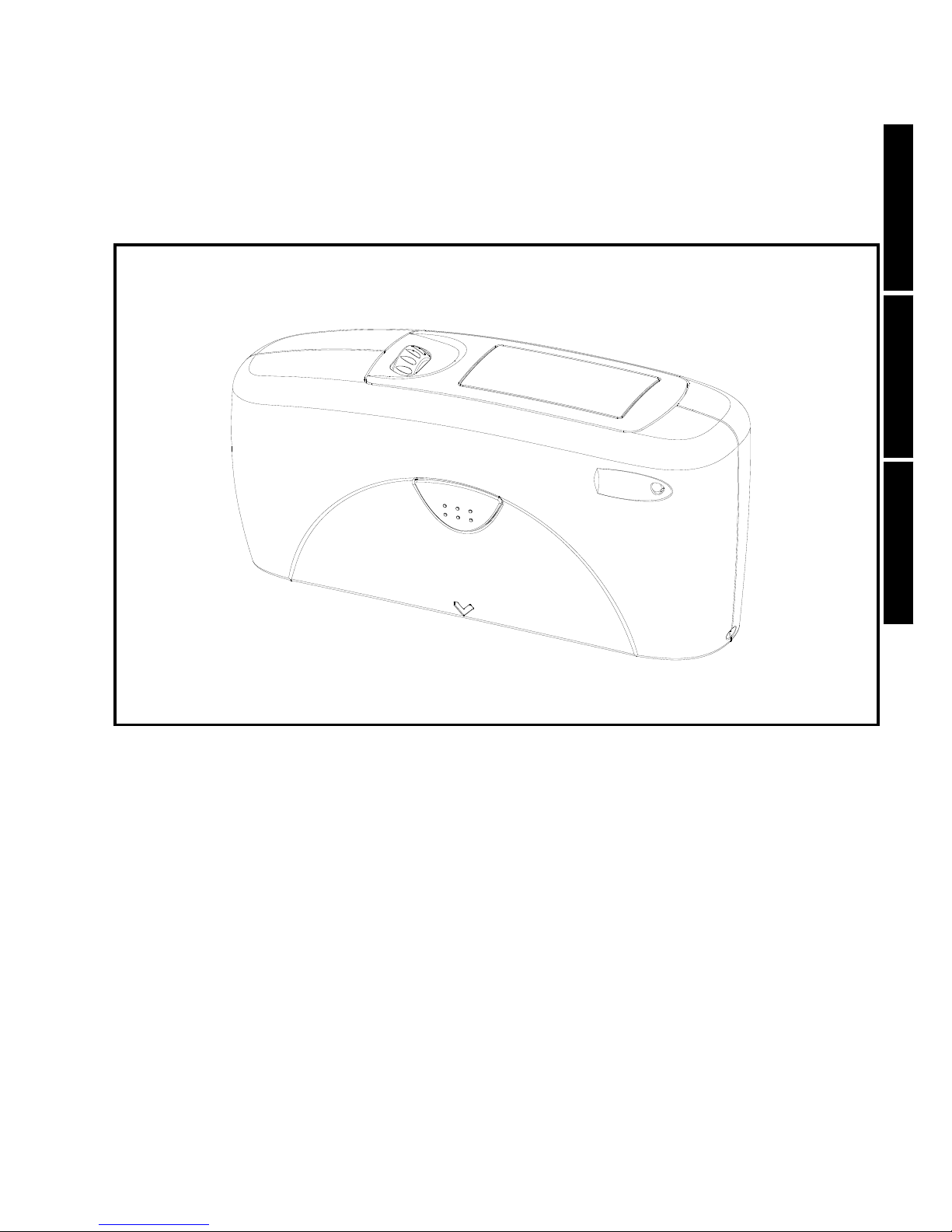
¬ $ESCRIPTION¬OF¬THE¬SYSTEM
4HE¬MEASUREMENT¬UNITS¬CAN¬BE¬
USED¬TO¬DETERMINE¬THE¬GLOSS¬LEVEL¬
AND¬lLM¬THICKNESS¬OF¬PAINT¬AND¬
COATINGS¬ON¬MAGNETIC¬&E¬AND¬
NONMAGNETIC¬SUBSTRATES¬.&E
,IGHT¬IS¬DIRECTED¬AT¬THE¬SURFACE¬OF¬
THE¬SAMPLE¬AT¬A¬DElNED¬ANGLE¬AND¬
THE¬REmECTED¬LIGHT¬IS¬MEASURED¬
PHOTOELECTRICALLY¬REmECTOMETER¬
$EPENDING¬ON¬THE¬TYPICAL¬GLOSS¬
LEVEL¬OF¬THE¬TEST¬OBJECT¬DIFFERENT¬
ANGLES¬GEOMETRY¬ARE¬TO¬BE¬USED¬
4HE¬MEASUREMENT¬UNIT¬IS¬¬
EQUIPPED¬WITH¬STANDARD¬¬
GEOMETRIES¬OF¬ª¬ª¬AND¬ª
)N¬ADDITION¬TO¬MEASURING¬INDIVIDUAL¬¬
GLOSS¬VALUES¬IT¬IS¬ALSO¬POSSIBLE¬TO¬¬
RECORD¬SAVE¬AND¬STATISTICALLY¬¬
EVALUATE¬SERIES¬OF¬MEASUREMENTS¬
CONSISTING¬OF¬UP¬TO¬¬VALUES¬
4HE¬OPERATE¬BUTTON¬AND¬SCROLL¬
WHEEL¬ARE¬USED¬TO¬CONTROL¬THE¬¬
SYSTEM¬3YSTEM¬OPERATION¬IS¬¬
SUPPORTED¬BY¬DISPLAY¬MESSAGES¬
AUTODIAGNOSIS¬AND¬ERROR¬¬
MESSAGES¬9OU¬CAN¬SELECT¬¬
'ERMAN¬%NGLISH¬&RENCH¬3PANISH¬
)TALIAN¬OR¬*APANESE¬+ATAKANA¬AS¬
THE¬DISPLAY¬LANGUAGE¬
4HE¬MEASUREMENT¬UNIT¬CONFORMS¬¬
TO¬THE¬STANDARDS¬$).¬¬¬
)3/¬¬!34-¬$¬¬AND¬¬
"3¬¬0ART¬$¬¬

7
English
Safety instructions 2
If you use the unit properly, there are no hazards to fear – none of
a mechanical nature and none caused by electrical shock.
The manufacturer assumes no liability for damages caused by
failure to observe the safety and general instructions.
Please use only accessories that are available for the unit.
Improper use of accessories will render the warranty null and void.
If there is reason to believe that the unit can longer be operated
without presenting a hazard, it should be taken out of operation
and prevented from being turned on unintentionally. Operation
without presenting a hazard is no longer possible if the unit shows
visible signs of damage or if it is no longer working.
Do not perform any repairs on the unit, neither mechanical nor
electrical yourself. The unit must be opened by trained
professionals only. Please contact our customer service
department in such cases. They will be happy to assist you as
quickly as possible.

8
English
2 Safety instructions
Only instruments complying with the requirements for safety extra
low voltage may be connected to the RS 232 interface.
In case an external power supply is used, please pay attention that
the nominal voltage of the power supply (see identification plate
on the power supply) corresponds to the mains voltage of the
mains socket.
Your instrument is cutt off from power supply by
a) taking out the battery or
b) in case of external power supply by pulling the power supply
out of the mains socket.
Please take care that the power supply is accessible at any time.
In case you intend not to use the instrument for a longer period of
time, take out the battery in order to avoid that the battery leaks
inside the instrument and thus causes damage.

9
English
General Information 3
The measurement unit consists of sensitive optical and electronic
precision parts. Provent it from being dropped or bumped or jostled!
Do not hold the unit by the measurement aperture. You should not allow
any foreign objects to get into this opening.
Do not expose the unit to direct sunlight for extended periods of time. Do
not store it in a hot or dusty environment. The case that comes with the
unit offers the best protection when the unit is being stored.
Avoid prolonged high relative humidity and do not allow water to form
from condensation (see Technical data).
Protect the measuring unit from moisture, chemicals and corrosive
vapors.
Check the film thickness sensor at regular intervals. The sensor must
have direct contact with the test surface. Therefore, correct measurement
results can only be obtained with a clean measuring probe. Keep the
sensor free of any dirt.
The holder and the unit housing are resistant to many solvents. However,
we cannot guarantee resistance to all chemicals. You should therefore
use a soft, moist cloth for cleaning. For clean excessive dirt and dust, use
ethanol or cleaning alcohol. Do not use any acetone!
Please note that batteries are special refuse and shall not be disposed of
together with household refuse. Pay attention to the producers
instruction or how to dispse of the battery.

%NGLISH
¬ #OMMISSIONING¬AND¬POWER¬SUPPLY¬ ¬
"EFORE¬PUTTING¬THE¬UNIT¬IN¬¬
OPERATING¬READ¬THE¬OPERATING¬
INSTRUCTIONS¬AND¬PAY¬ATTENTION¬TO¬
OPERATION¬THE¬SAFETY¬INSTRUCTIONS¬
AND¬GENERAL¬INSTRUCTIONS¬IN¬¬
3ECTION¬¬5NPACK¬THE¬DEVICE¬AND¬
CHECK¬TO¬MAKE¬CERTAIN¬ALL¬PIECES¬
HAVE¬BEEN¬INCLUDED¬WITH¬DELIVERY¬
FOR¬SCOPE¬OF¬DELIVERY¬SEE¬3ECTION¬
$ELIVERY¬NOTES
A¬0OWER¬SUPPLY¬
BATTERY¬¬OPERATED
4HE¬BATTERY¬MUST¬BE¬PLACED¬IN¬THE¬¬
MEASURING¬UNIT¬FOR¬OPERATION¬¬
SERVICE¬4HE¬DEVICE¬RUNS¬ON¬ONE¬
!!¬6¬ALKALINE¬BATTERY¬
5SE¬ONLY¬ALKALINE¬BATTERIES¬
!!,2
$EPENDING¬ON¬THE¬EXACT¬BRAND¬
THE¬CAPACITY¬OF¬EACH¬BATTERY¬IS¬
SUFlCIENT¬FOR¬ABOUT¬¬¬
MEASUREMENTS¬7HEN¬THE¬BATTERY¬
VOLTAGE¬FALLS¬BELOW¬THE¬REQUIRED¬
MINIMUM¬VOLTAGE¬IN¬THE¬COURSE¬OF¬
OPERATION¬THE¬FOLLOWING¬MESSAGE¬
APPEARS¬ON¬THE¬DISPLAY¬
¬ ¬ "ATTERY¬LOW¬
4O¬ENSURE¬THAT¬THE¬UNIT¬IS¬ALWAYS¬
READY¬FOR¬OPERATION¬IT¬IS¬¬
RECOMMENDED¬TO¬HAVE¬A¬SPARE¬
BATTERY¬HANDY¬ESPECIALLY¬WHEN¬
PERFORMING¬MEASUREMENTS¬IN¬THE¬
lELD
#HANGING¬THE¬BATTERY
4O¬INSERT¬OR¬CHANGE¬THE¬BATTERY¬
OPEN¬THE¬BATTERY¬COMPARTMENT¬
4HE¬EASIEST¬WAY¬TO¬DO¬THIS¬IS¬BY¬
TURNING¬THE¬COVER¬WITH¬A¬COIN¬ONE
EIGHTH¬OF¬A¬ROTATION¬TO¬THE¬LEFT¬4URN¬
THE¬DEVICE¬BACK¬AROUND¬AND¬ALLOW¬
THE¬OLD¬BATTERY¬AND¬THE¬BATTERY¬
COMPARTMENT¬COVER¬TO¬SLIDE¬INTO¬
YOUR¬HAND
)NSERT¬THE¬NEW¬BATTERY¬WITH¬THE¬
POSITIVE¬TOP¬END¬lRST¬INTO¬THE¬
BATTERY¬COMPARTMENT¬AND¬SET¬THE¬
BATTERY¬COMPARTMENT¬COVER¬IN¬
PLACE¬AGAIN¬,OCK¬THE¬COVER¬BY¬
TURNING¬IT¬ONEEIGHTH¬OF¬A¬ROTATION¬
TO¬THE¬RIGHT
#HANGING¬THE¬BATTERY
AA/LR6

%NGLISH
¬ #OMMISSIONING¬AND¬POWER¬SUPPLY¬ ¬
B¬0OWER¬SUPPLY¬BY¬EXTERNAL¬PO
WER¬SUPPLY¬OPTIONAL¬SEE¬¬
$ELIVERY¬NOTES¬!CCESSORIES
0LEASE¬NOTE¬)N¬CASE¬YOU¬OPERATE¬
THE¬INSTRUMENT¬WITH¬A¬POWER¬¬
SUPPLY¬IT¬IS¬VITAL¬THAT¬YOU¬TAKE¬THE¬¬
BATTERY¬OUT¬OF¬THE¬BATTERY¬¬
COMPARTMENT¬%LSE¬THE¬INSTRUMENT¬
IS¬CONTINUED¬TO¬BE¬POWERED¬BY¬THE¬
BATTERY
)N¬ORDER¬TO¬CONNECT¬THE¬INSTRUMENT¬
TO¬THE¬EXTERNAL¬POWER¬SUPPLY¬THE¬
SUITABLE¬END¬OF¬THE¬POWER¬SUPPLY¬¬
CABLE¬HAS¬TO¬BE¬INSERTED¬IN¬THE¬¬
INTERFACE¬OF¬THE¬INSTRUMENT
4HE¬CONNECTION¬TO¬THE¬0#¬IS¬DONE¬
VIA¬THE¬SUB$¬PINS¬PLUG¬OF¬THE¬
POWER¬SUPPLY¬CABLE
&OR¬MORE¬INFORMATION¬ABOUT¬THE¬
OPERATION¬WITH¬23¬¬PLEASE¬REFER¬
TO¬THE¬CHAPTER¬)NTERFACE

12
English
Measurement unit and protective holder
1 Mode scroll wheel: used to turn the unit on and for menu selection
2 Display for user guidance and displaying measurement values
3 Green signal lamp: measurement active; red: error
4 Operate button (measurement button): used to activate
measurements
5 Protective holder
6 Calibrating standard
7 Mark for the measurement aperture
8 Interface for connecting to a PC
9 Thickness sensor
1
2
4
3
7
8
5
6
5 Control elements
9

13
English
Control elements 5
The basic system consists of the
measuring device and the
protective holder.
The protective holder is used for
calibration and to store the
measurement unit. Calibration is
performed inside the holder
automatically at the touch of a
button. The gloss standard
required for this purpose is kept in
the holder and is positioned in
such a manner that calibration is
always performed at the same
point.
When the device is turned on
inside the holder, it performs a self-
test (autodiagnosis).
If you will not be using the
measuring unit, please store it in
the protective holder. In this way
the measurement optics are
protected from dirt and dust and
the calibration standard is always
readily available.
The operate button and scroll
wheel are used to control the
system. Pressing the wheel turns
the unit on and causes a menu to
be displayed. All settings within the
menus are made by turning and
pressing the wheel.
Pressing the operate button starts
measurements or performs
functions that are displayed. In
addition, you can return from the
various menus to mode with the
operate button. System operation
is supported by an autodiagnosis
test, comments and error
messages. Measurement values
and comments appear in the
display.

%NGLISH
¬ 'ETTING¬STARTED¬ ¬
4URNING¬ON¬THE¬UNIT¬AND¬
¬MEASURING
4O¬TURN¬ON¬THE¬UNIT¬PRESS¬THE¬MODE¬
SCROLL¬WHEEL
)NFORMATION¬ON¬THE¬DATE¬AND¬LAST¬
CERTIlCATION¬APPEARS¬IN¬THE¬DISPLAY¬
)F¬THE¬DEVICE¬WAS¬TURNED¬ON¬IN¬ITS¬
HOLDER¬THE¬AUTODIAGNOSIS¬TEST¬IS¬
PERFORMED¬SEE¬THE¬SECTION¬ON¬¬
#ALIBRATION
4HEN¬THE¬UNIT¬SWITCHES¬INTO¬THE¬LAST¬¬
MEASUREMENT¬MODE¬TO¬BE¬¬
SELECTED¬
0RESSING¬OPERATE¬INITIATES¬¬
MEASUREMENTS
4HE¬DISPLAY¬OF¬MEASUREMENT¬¬
RESULTS¬ON¬THE¬SCREEN¬MAY¬BE¬
BROKEN¬DOWN¬INTO¬THE¬FOLLOWING¬
ELEMENTS
!¬ 7HEN¬$IFFERENCE¬MEASUREMENT¬
IS¬TURNED¬ON¬THE¬NAME¬OF¬THE¬¬
REFERENCE¬THAT¬IS¬SELECTED¬IS¬¬
DISPLAYED¬HERE
"¬ )F¬3AVE¬IS¬SELECTED¬THE¬MEMORY¬
AREA¬THAT¬IS¬SELECTED¬APPEARS¬AT¬THE¬
TOP¬LEFT¬AND¬FOR
#¬ THE¬SAMPLE¬NAME¬BLOCK¬NAME
$¬ )F¬3TATISTICS¬OR¬#ONTINUOUS¬IS¬
TURNED¬ON¬THE¬NUMBER¬OF¬MEASURE
MENTS¬PERFORMED¬OR¬SELECTED¬IS¬
DISPLAYED¬HERE

15
English
Getting started 6
The measurement values appear in
the lower part of the display area.
The size of the numbers depends
on whether Statistics or Difference
measurement has been activated
and on the number of geometries
displayed. Depending on the
measurement mode, a header line
also appears for the measurement
values.
Navigation
All control functions are controlled
by the mode scroll wheel. Pressing
the wheel causes a menu to
appear in the display. Turning the
wheel allows you to move the
black mark to the desired function
and to select or activate it by
pressing the wheel.
What functions are displayed in the
menu depends on the settings in
the main menu. The main menu is
the “central” level and can always
be reached quickly.
Certain rules apply within the
menus to make it easier to
navigate:
A black triangle to the right of a
function indicates that selecting
this function will take you to a sub-
menu.
A check mark on the right indicates
that the function in question has
been activated.

16
English
6 Getting started
You can use the arrow at the top
right to switch the display back by
one level.
Arrows pointing up or down
indicate that there are other menu
options above or below the part of
the menu that is visible. To reach
these menu options, simply turn
the scroll wheel in the direction in
which the arrow is pointing.
You can quickly switch back from
the menus to the measurement
display by using the operate
button. In some cases this button
also has another function, but that
will be indicated in the display (for
example Confirm -> operate).
Change names/numbers
For some functions, you can enter
or change the date or name. The
arrow pointing upward marks the
position that can be changed. To
change the character, turn the
scroll wheel. When you press the
wheel, the arrow jumps to the next
character.
After you have adjusted the last
character or number, confirm your
input by pressing the wheel.

17
English
Getting started 6
When you enter the name, the
arrow jumps to the first character.
This allows you to correct any
inadvertent incorrect entries. You
can confirm the name in these
menus at any time with the operate
key.

18
English
7 Overview of main menu
Measurement without statistical evaluation.
Multiple measurement with statistics.
Measurement repetition (measuring interval adjustable).
Simplest mode: without saving and difference
Opens the “Mode” menu again with the previous
setting.
Select geometry and thickness sensor (Fe/NFe)
Save functions for samples:
Turn saving on/off.
Select memory area from list.
Up to 50 memory areas can be created.
Pre-set memory areas (M60°...) cannot be deleted.
Bring up contents of memory (use scroll wheel).
Settings for difference mode:
Turn difference measurement on/off.
Measure reference.
Select reference (if saved).
Save up to 50 references and enter limit values for
Pass/Fail.
Delete individual references.
Enter/change limit values for Pass/Fail.
Calibrate, change cal. values GU - % scale.
The following can be used together simultaneously:
• Save with:
• Difference with:
Mode
Sample mode
Statistics
Continuous
Basic mode
Advanced mode
Geometry/Sensor
Save
Save
Select memory
Create memory
Delete memory
Display memory
Difference
Difference
Measure reference
Select reference
Create reference
Delete reference
Change reference
Calibration
Setup
Sample mode, Statistics, Continuous
Sample mode, Statistics
Language, Display time, Date/Time, Beeper.

19
English
Mode and sample measurement 8
You can select from among diffe-
rent types of measurement
recording and evaluation in the
Mode menu. The mode that is
activated is identified by a check
mark.
Single measurements can be
performed without statistical
evaluation in Sample mode.
The results can be saved and
compared with a reference.
When Save is turned on, a name
is suggested after every
measurement. You can confirm
this name directly or change it.
If you would like to delete the last
measurement, press the scroll
wheel and select the appropriate
menu item.
Other manuals for micro-TRI-gloss ?
2
Table of contents
Languages:
Other BYK Measuring Instrument manuals

BYK
BYK LCM III User manual

BYK
BYK LC 3 User manual

BYK
BYK haze-gard plus User manual

BYK
BYK spectro2profiler Manual

BYK
BYK multi-angle User manual

BYK
BYK haze-gard plus Instruction Manual

BYK
BYK micro-TRI-gloss ? User manual

BYK
BYK micro-TRI-color 345 000 015 Series User manual

BYK
BYK micro-gloss Installation manual

BYK
BYK spectro2guide User manual