Spender DHS3600 User manual

Service manual SPENDER DHS3600
1
SERVICE MANUAL
SPENDER
MODEL DHS 3600

Service manual SPENDER DHS3600
2
CONTENTS
SPECIFICATION 3
CIRCUIT DESCRIPTION 4
ADJUSTMENT INSTRUMENT LIST 7
ADJUSTMENT PROCEDURES 8
LCD DISPLAY 9
SEMICONDUCTOR IDENTIFICATION 9-12
MAIN PC BOARD (TOP VIEW WITH COMPONENTS) 13
MAIN PC BOARD (TOP VIEW) 14
MAIN PC BOARD (BOTTOM VIEW WITH COMPONENTS) 15
MAIN PC BOARD (BOTTOM VIEW) 16
KEYBOARD PC BOARD (TOP VIEW WITH COMPONENTS) 17
KEYBOARD PC BOARD (TOP VIEW)… 18
KEYBOARD PC BOARD (BOTTOM VIEW WITH COMPONENTS) 19
KEYBOARD PC BOARD (BOTTOM VIEW) 20
ADJUSTMENT POINTS 21-22
BILL OF MATERIAL 23-25
BLOCK DIAGRAM 26
SCHEMATIC DIAGRAM

Service manual SPENDER DHS3600
3
SPECIFICATIONS
GENERAL
FREQUENCY RANGE…………………………………………………… 245.000 245.9875 MHz.
CHANNEL STEP………………………………………………………….. 12.5KHz.
FREQUENCY GENERAL………………………………………………... SYNTHESIZER (PLL)
MODULATION TYPE…………………………………………………….. FM (F3E)
DIMENSION……………………………………………………………….. 89(H)×53(W)×30(D) mm
WEIGHT (WITH BATTERY)……………………………………………… Approx. 230g
RECEIVER
SENSITIVITY……………………………………………………………… < 0.20µV at 12dB SINAD
SELECTIVITY……………………………………………………………... 60dB
SPURIOUS RESPONSE………………………………………………… 60dB
DISTORTION…………………………………………………………….... LESS THAN 5%
AUDIO OUPUT POWER……………………………………………….… > 400mW at 4Ω
TRANSMITTER
POWER OUTPUT………………………………………………………… 4.5W
FREQUENCY STABILITY……………………………………………….. ±5ppm (-20ºC ~ +60ºC)
HARMONIC AND SPURIOS EMMISION…………………………….… 60dB
FREQUENCY DEVIATION…………………………………………….… NO MORE THAN ±2.5kHz
AUDIO DISTORTION…………………………………………………..… LESS THAN 5%
FREQUENCY TABLE (80 CHANNELS)
UNIT: MHz
CH. FREQ. CH. FREQ. CH. FREQ. CH. FREQ. CH. FREQ.
1 245.0000 17 245.2000 33 245.4000 49 245.6000 65 245.8000
2 245.0125 18 245.2125 34 245.4125 50 245.6125 66 245.8125
3 245.0250 19 245.2250 35 245.4250 51 245.6250 67 245.8250
4 245.0375 20 245.2375 36 245.4375 52 245.6375 68 245.8375
5 245.0500 21 245.2500 37 245.4500 53 245.6500 69 245.8500
6 245.0625 22 245.2625 38 245.4625 54 245.6625 70 245.8625
7 245.0750 23 245.2750 39 245.4750 55 245.6750 71 245.8750
8 245.0875 24 245.2875 40 245.4875 56 245.6875 72 245.8875
9 245.1000 25 245.3000 41 245.5000 57 245.7000 73 245.9000
10 245.1125 26 245.3125 42 245.5125 58 245.7125 74 245.9125
11 245.1250 27 245.3250 43 245.5250 59 245.7250 75 245.9250
12 245.1375 28 245.3375 44 245.5375 60 245.7375 76 245.9375
13 245.1500 29 245.3500 45 245.5500 61 245.7500 77 245.9500
14 245.1625 30 245.3625 46 245.5625 62 245.7625 78 245.9625
15 245.1750 31 245.3750 47 245.5750 63 245.7750 79 245.9750
16 245.1875 32 245.3875 48 245.5875 64 245.7875 80 245.9875

Service manual SPENDER DHS3600
4
CIRCUIT DESCRIPTION
1. FREQUENCY CONFIGURATION
The receiver utilizes double conversion. The first IF is 45 MHz and the second IF is 455 kHz. The first
local oscillator signal is supplied from the X2 (44.545MHz).
2. RECEIVER SYSTEM
2-1 Front End (RF AMP)
The signal coming from the antenna passes through the transmit/receive switching diode circuit, is
amplified by the RF amplifier (Q10), and passes through a BPF. Then passes through the low-pass
filters and goes to the mixer.
2-2 First Mixer
The signal from the front end is mixed with the first local oscillator signal generated in the PLLcircuit
by Q11 to produce a first IF frequency of 45 MHz. The resulting signal passes through the F1,F2
MCF to cut the adjacent spurious and provide the optimum characteristics, such as adjacent
frequency selectivity.
2-3 IF Amplifier
The signal then passes through the first IF (Q35), and is amplified and goes to the IF IC (U8). U8
incorporates the functions of the second OSC, second mixer, second IF amplifier, detector, noise
amplifier, and noise detector. The signal input to the IC is mixed with the RF signal of the second
OSC to produce a 455kHz second IF signal. The signal is amplified by the IF amplifier. The signal
passes through the ceramic filter (F3) to provide the necessary selectivity. Finally, the signal is
detected by the IC (U8) and output as an AF signal.
2-4 AF Amplifier
The AF signal from the IF IC is amplified and decoded by IC (U8), and the signal passes through AF
VOL circuit and enters the audio power amplifier IC (U1) to drive the speaker.
2-5 Squelch
Part of the AF signal from the IF IC enters the FM IC again, and the noise component is amplified
and rectified by a filter and an amplifier to produce a DC voltage corresponding to the noise level.
The DC signal from the FM IC goes to the analog port of the microprocessor (U4). U4 determines
whether to output sounds from the speaker by checking whether the input voltage is higher or lower
than the preset value. To output sounds from the speaker, U4 sends a high signal to the MUTE and
turns U1 on though Q4, Q14, Q17.

Service manual SPENDER DHS3600
5
2-6 Receive Signaling
1) CTCSS
300 Hz-and-higher audio frequencies of the signal output from the IF IC are cut by a low-filter (U5).
The resulting signal enters the microprocessor (U4). U4 determines whether the CTCSS matches
the preset value, and controls the MUTE and the speaker output sounds in line with the squelch
results of that content.
3. PLL CIRCUIT
The PLL circuit generates the first local oscillator signal for reception and the RF signal for
transmission.
3-1 PLL
The receiver has a VCO (Q301), and the transmitter has another VCO (Q303). The generated signal
passes through Q20 buffer and Q17 amplifies. U3 incorporates the reference oscillation divider and
phase comparator functions. The input signal is divided into the signal according to the divide ratio
data from the microprocessor (U4). This signal divided from the reference signal enter the phase
comparator to produce a differential signal. The frequency control signal is output from the charge
pump. The signal passes through the passive LPF and goes to varicap to control the VCO frequency.
3-2 Reference Oscillator Circuit
The reference oscillator circuit in the PLL IC produces the 12.8MHz PLL reference frequency. To
stabilize the frequency, the characteristics of the 12.8MHz crystal oscillator are controlled.
4. TRANSMITTER
4-1 Transmit Audio
The modulation signal from the microphone is amplified by U9, passes through a reemphasis circuit,
and is amplified by the other to perform operation. Then the resulting signal goes to the VCO through
the VCO modulation terminal for direct FM modulation.
4-2 CTCSS Encoder
Anecessary signal for CTCSS encoding is generated by the U4 and U5, and is FM-modulated to the
PLL reference signal. Since the reference OSC does not modulate the loop characteristic frequency
or higher, modulation is performed at the VCO side by adjusting the balance.
4-3 VCO and RF Amplifier
The modulation signal is modulated to VCO by D305. The RF signal from the PLLis amplified by Q17
and Q33 to the sufficient level to drive the power transistor.

Service manual SPENDER DHS3600
6
4-4 Final Module
The VHF power transistor 2SK3476 is used to amplify the transmission power.
4-5 ANT Switch and LPF
The signal from the power transistor passes through the D101 SW and LPF and is output from the
ANT terminal. U4 and PTT are used to switch between transmission and reception.
4-6 Control System
The CPU U4 operates at 3.6864 MHz clocks. U6 controls the LCD driver.
4-7 Power Supply
The main of the system control is DC 7.4V.
Service manual SPENDER DHS3600
7
ADJUSTMENT INSTRUMENT LIST
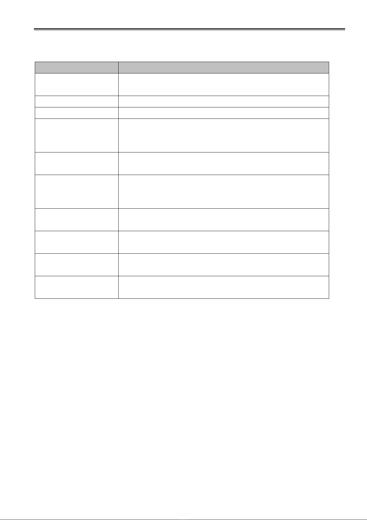
INSTRUMENT SPECIFICATION
VHF Signal
Generator Frequency Range: 0.1 ~ 300MHz
Output Level: 0.1uV ~ 50mV
Digital Voltmeter Measuring Range: 1mV ~ 15V
Distortion Meter Measuring Range: 0.1 ~ 20%
Frequency Counter Frequency Range: 0.1 ~ 300MHz
Accuracy: ±1ppm or Better
Sensitivity: 100mV or Better
Oscilloscope Frequency Range: DC ~ 20MHz
Measuring Range: 0.01 ~ 15V
RF Power Meter Measuring Range: 0.1 ~ 10W
Frequency Range: 1 ~ 300MHz
Impedance: 50ohm
Stabilized Power Supply Output Voltage: 0 ~ 15VDC
Output Current: 3A or more
External Load Connection Type: 3.5Φmono
Impedance: 4ohm/0.5W
FM Modulation Analyzer Frequency Range: 20Hz ~ 5kHz
Measuring Range: 0 ~ ±10kHz
Audio Signal Generator Frequency Range: 20Hz ~ 5kHz
Output Level: 1mV ~ 1V

Service manual SPENDER DHS3600
8
ADJUSTMENT PROCEDURES
VCO SECTION
Item Condition Measurement Adjustment Specifications
Test Equipment Terminal Parts Method /Remarks
1.Setting 1) Power supply voltage
Battery terminal: 7.4V
2.VCO lock 1) CH: TX Lo Digital Voltmeter C319 Adjust to 2.0V
Voltage 2) CH: TX Hi Digital Voltmeter
3) CH: RX Lo Digital Voltmeter C306 Adjust to 2.0V
4) CH: RX Hi Digital Voltmeter
TRANSMITTER SECTION
Item Condition Measurement Adjustment Specifications
Test Equipment Terminal Parts Method /Remarks
1.Transmit 1) CH: TX Lo RF Power meter ANT L10, L13 Adjust it to
Power PTT: ON Ammeter 4.5W Check
2) CH: TX Hi RF Power meter ANT L10, L13 Adjust it to
PTT: ON Ammeter 4.5W Check
2.Transmit 1) CH: TX Center Frequency ANT VR2 Adjust to
Frequency PTT: ON counter ±500Hz or less
3.Modula- 1) CH: TX Center Modulation ANT VR1 Adjust to ±5kHz
tion analyzer
Oscilloscope MIC
Audio Signal
Generator
RECEIVER SECTION
Item Condition Measurement Adjustment Specifications
Test Equipment Terminal Parts Method /Remarks
1. Sensiti- 1) CH: RX Lo Oscilloscope ANT L1, L2, Adjust to the min.
vity CH: RX Center Distortion meter SPK L20, L21 Distortion and
best
CH: RX Hi
Signal to noise
ratio
Service manual SPENDER DHS3600
9
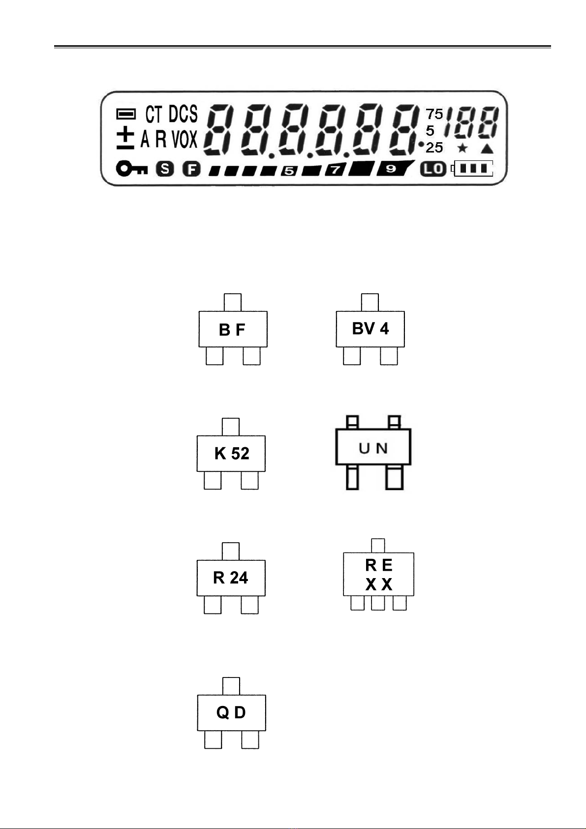
LCD DISPLAY DESCRIPTION
SEMICONDUCTOR IDENTIFICATION
2SS268 B561
2SK508 3SK240
2SC3356 2SC3357
2SC1923

Service manual SPENDER DHS3600
10
SEMICONDUCTOR IDENTIFICATION
24C04 (EEPROM)
LM386
HT1621B LCD DRIVER
Service manual SPENDER DHS3600
11
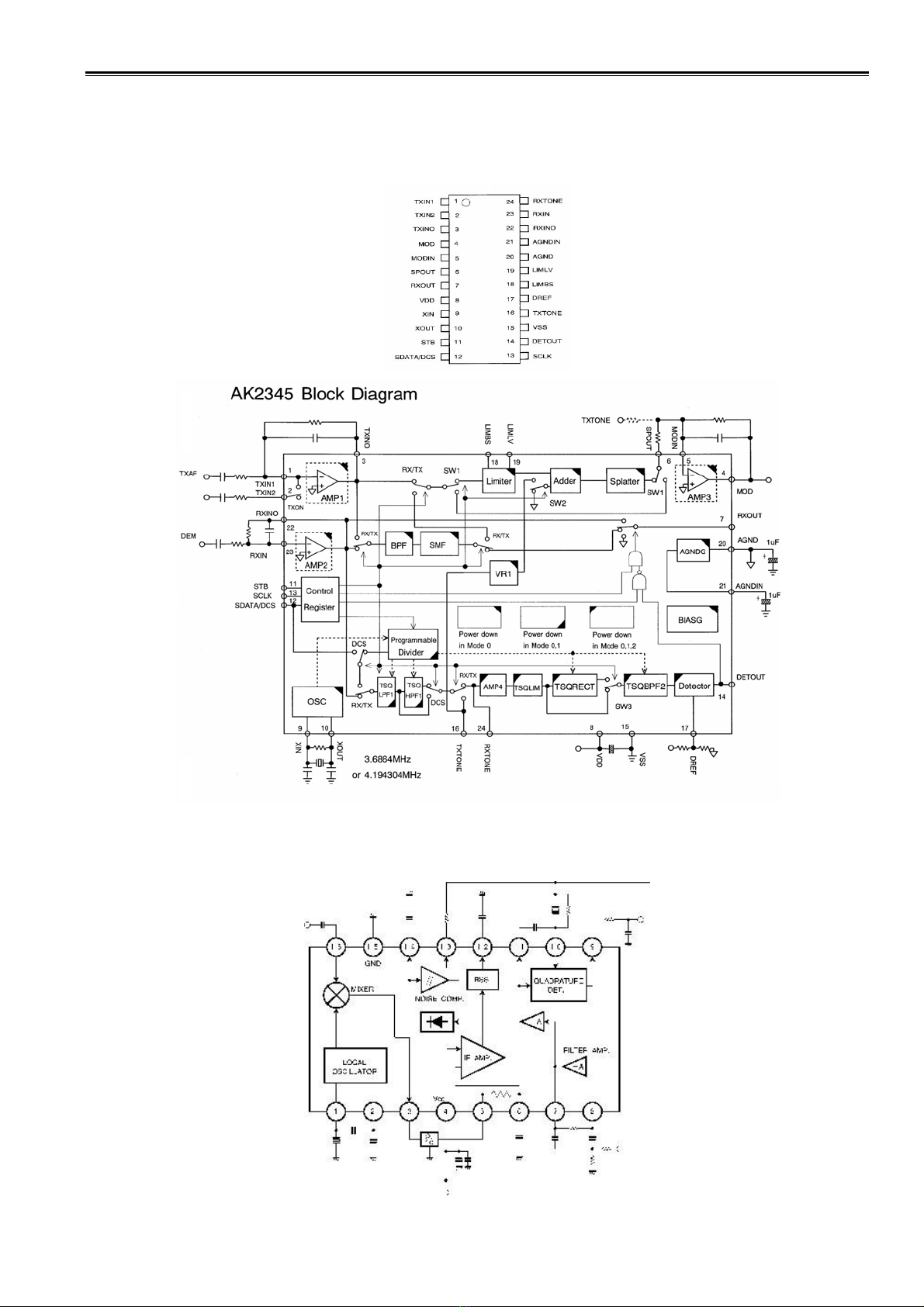
SEMICONDUCTOR IDENTIFICATION
AK2345

Service manual SPENDER DHS3600
12
TA31136
SEMICONDUCTOR IDENTIFICATION
HT46R23
Service manual SPENDER DHS3600
13
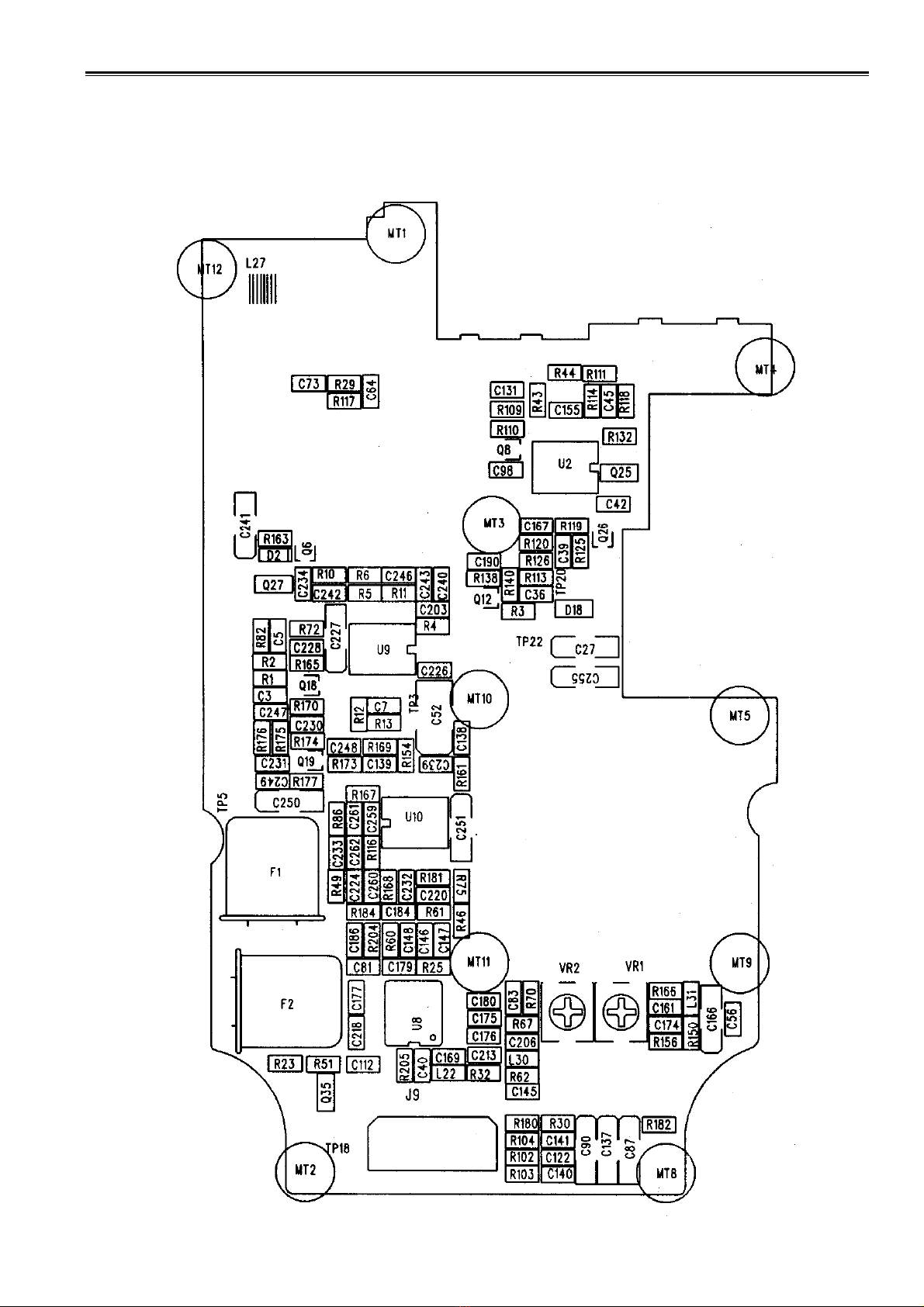
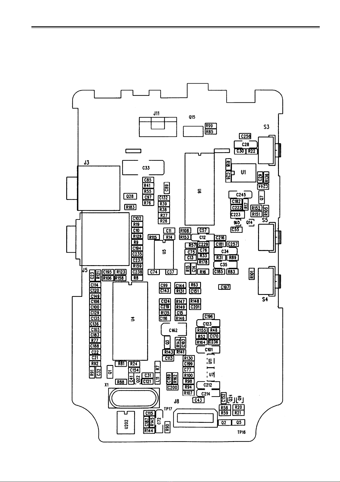
MAIN PC BOARD (TOP VIEW WITH COMPONENT)

Service manual SPENDER DHS3600
14
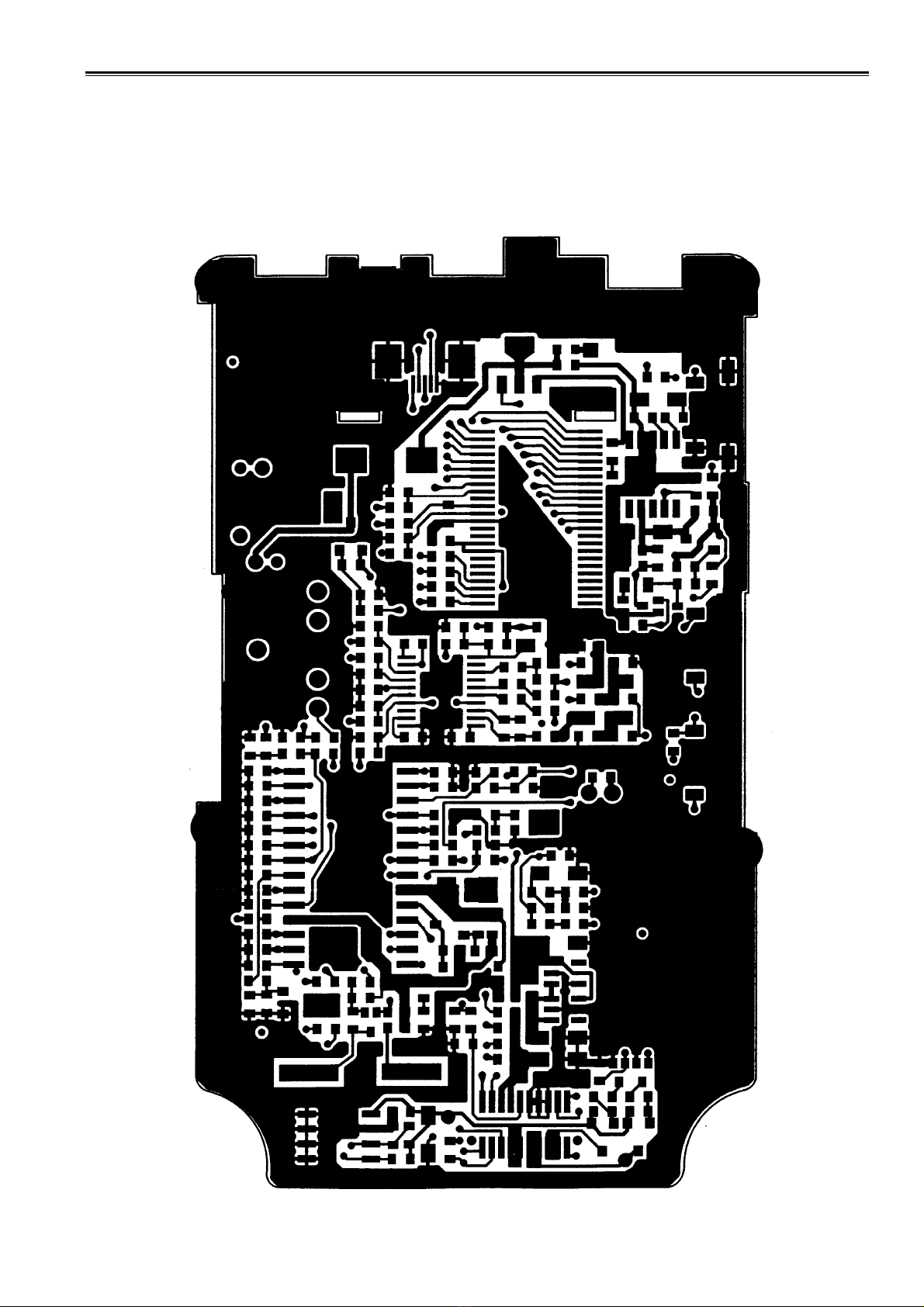
MAIN PC BOARD (TOP VIEW)

Service manual SPENDER DHS3600
15
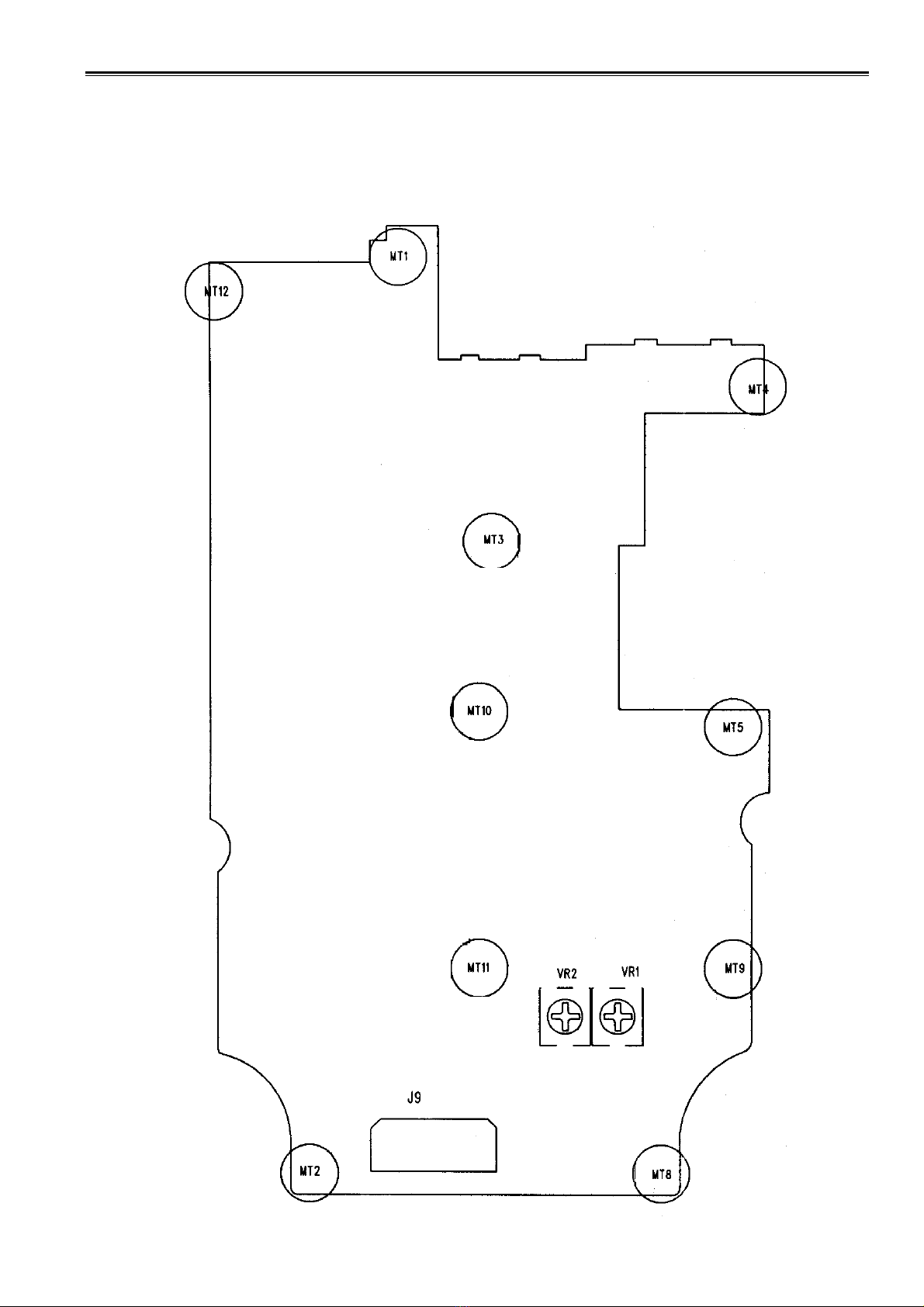
MAIN PC BOARD (BOTTOM VIEW WITH COMPONENTS)
Service manual SPENDER DHS3600
16
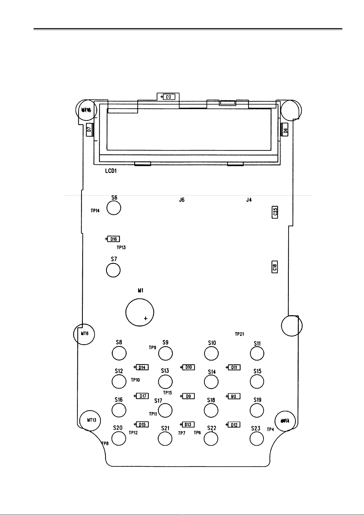
KEYBOARD PC BOARD (TOP VIEW WITH COMPONENT)

Service manual SPENDER DHS3600
17
KEYBOARD PC BOARD (TOP VIEW)
Service manual SPENDER DHS3600
18
KEYBOARD PC BOARD (BOTTOM VIEW WITH COMPONENTS)
Service manual SPENDER DHS3600
19
KEYBOARD PC BOARD (BOTTOM VIEW)
Service manual SPENDER DHS3600
20
ADJUSTMENT POINTS
Table of contents
Other Spender Transceiver manuals


