manuals.online logo
Brands
  1. Home
  2. •
  3. Brands
  4. •
  5. jablotron
  6. •
  7. Transceiver
  8. •
  9. jablotron AC-116 User manual

jablotron AC-116 User manual

JABLOTRON ALARMS a.s.
Pod Skalkou 4567/33 46601 Jablonec n. Nisou
Czech Republic www.jablotron.com
||
|
The AC-116 Multi-channel hybrid transceiver
The AC-116 multi-channel hybrid transceiver (control unit) serves for the
independent control of up to 16 heating circuits. The actuators used are
thermo-electric valves on heaters or water distribution manifolds. For the
control of large premises up to 3 control units can be connected. This
combination then offers independent control of up to 48 circuits. The AC-116
control unit can work with the wireless thermostats of the TP-15x series and
also magnetic detectors like the JA-151M and JA-111M.
In combination with the AC-100LCD touchscreen there are additional
functions like: output for the heating circulation pump control, an output for
boiler and comfort settings of thermal limits, time schedules and many more
important parameters.
Installation
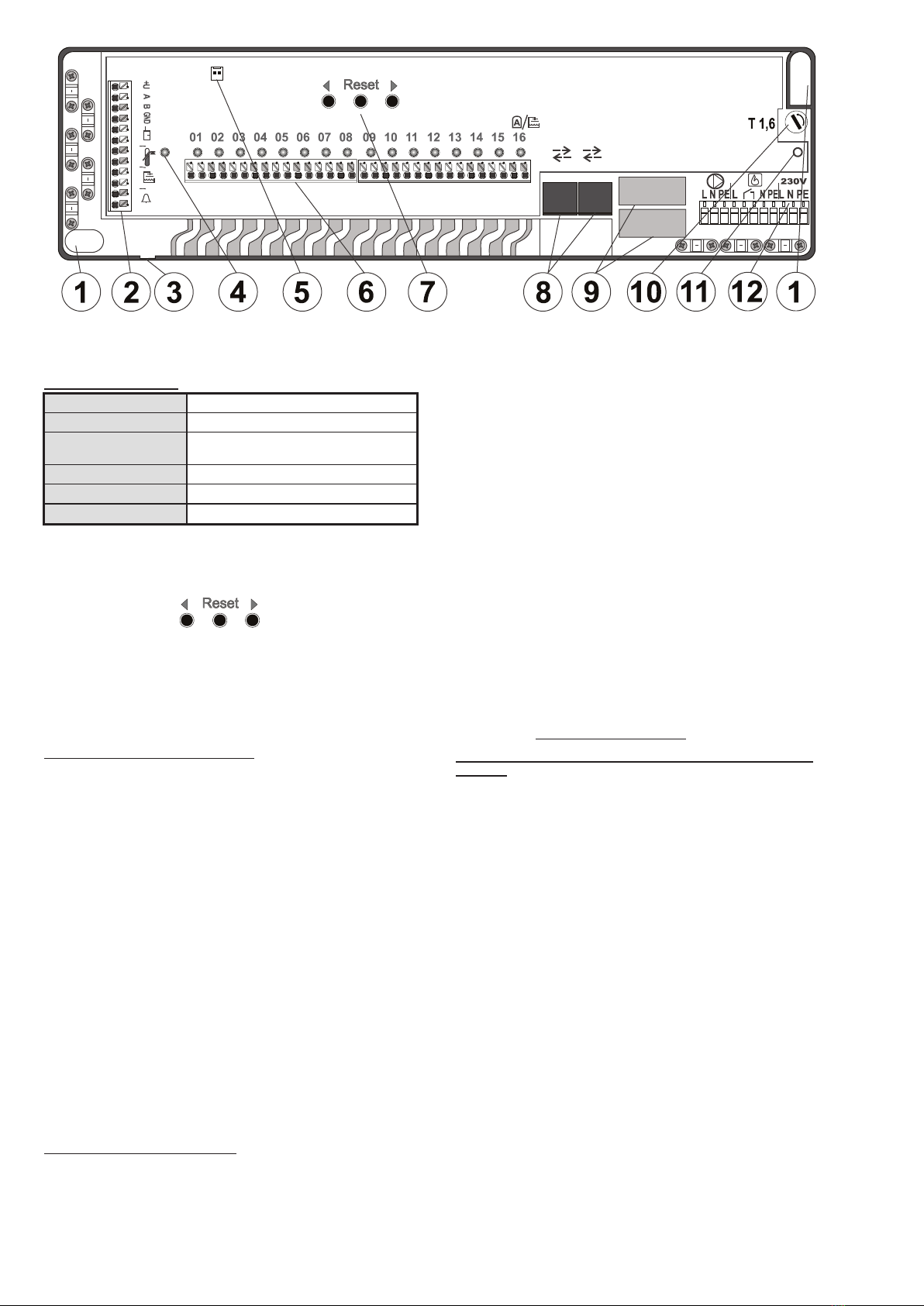
1. Release the screw (11) on the front panel and open the cover.
2. Fix the unit box to the DIN slot or mount it onto the selected place by the 2
screws inside the mounting holes (1). Think thoroughly about which inputs
and outputs you are going to use to prepare the needed cables at the
right places.
3. The mains connection is installed as a plug with a mains cable
connectable to an electrical socket protected by a 16 A circuit breaker.
The plug also has the role of an emergency disconnection point. Do not
connect the mains yet!
4. Install the needed cables from the sensors to the unit, BUS devices and
thermo-electric valves (use fixing channels and compression
mechanisms). When you are using round cables for the output, punch the
plastic membranes through on the bottom of the plastic box. A description
of each of the terminals and their functions can be found in the chapter
Popis svorek a jejich funkcí.
5. Close the cover and fix it by a screw (11). Turn on the mains and then
follow the instructions in the chapter Enrolling devices.
Description of the output terminals and
their functions
The function is described according to the factory settings. When the AC-
100LCD touchscreen is connected you can modify all parameters (checked by
* in the text). The temperature limits can be set up inside the thermostats. See
their installation manuals for details.
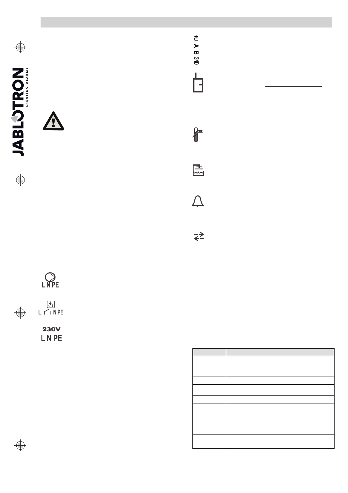
The relay of the circulation pump output terminals (use
external protection which serves as an emergency
disconnection point). Terminals provide mains power if any
output channel (6) is switched on, but they don´t ensure mains
isolation for electrical safety.
The boiler relay output terminals (use external protection
which serves as an emergency disconnection point). The
galvanically separated relay output terminals are switched on if
any output channel (6) is switched on. The “L” terminal provides
the mains power for the boiler pump.
Mains power terminals. The mains power connection is
solved by a flexi-cable with a plug. This power supply circuit is
protected by a 1.6 A (12) fuse.
PE terminals serves for the connection of the mains earth protection wire,
they must not be used for connection to the protective earth bonding of the
heating system metal parts. This has to be connected outside the control unit
box.
The output terminals of channels 1-16. The output channels (6) providing
24 V DC for thermo-electric valves. Each output has short circuit protection (if
the unit detects a higher current than 0.4A, then the output is automatically
disconnected and this state is indicated by the relevant LED on the front panel
of the unit. A relay for switching the heaters can also be connected, infrared
panels and so on. The only condition is that the maximum current must not
exceed 1.6 A. When this maximum is reached then the unit activates output
pulse switching mode. This allows the distribution of the maximum current to
every single thermo-electric valve. Thanks to the valves inertia this switching
has no negative influence (the only effect which it has is a little bit slower
opening of the valves). In combination with electric relays it could have a
negative influence because of permanent switching on/off.
Note:
- The output channels are not designed to switch devices which can control
semiconductor parts.
BUS output terminals serves for BUS device connection like the
JA-111M (BUS magnetic detector). The BUS devices can only be
connected when the main unit is completely disconnected from the
mains power!
Emergency mode. Input terminals serve for blocking the
activation of all outputs (6) at the same time. NO (normally open from
default): output channels 1-16 are turned on/off according to the
signals from thermostats. NC (normally closed): All channels are
turned off. A channel is activated only if the thermostat measures a
temperature drop under the Emergency (Stby) temperature. An
emergency status is indicated by the “ON” LED (4), see Table 2 for
details.
An emergency mode can also by activated wirelessly. When the
programmable thermostat is assigned to the “ON” channel then it can block
the heating according to the pre-defined weekly calendar. It is possible to link
an emergency mode activation with a JA-151M magnetic detector. Options
and enrolling principles can be found in the chapter Enrolling devices.
Protective thermometer. Terminals for the CP-201T(-NW)
detector which can detect exceeding a heating medium (heating
liquid) temperature of 65°C and at this moment turn off all 16 output
channels. A practical use is for protecting the under-floor heating
system and circuits when the heating medium is superheated to
avoid damaging the floor construction. If this detector is not
connected, the unit doesn´t offer this function.
Detector of the temperature from the boiler. Terminals for the
CP-201T(-NW) detector which controls output channel no.16. It is
switched according to the pre-set temperature for the boiler, time
schedule and temperature measured by this detector connected to
those terminals. The function is just available when the AC-100LCD
touchscreen and this detector are connected.
Alarm output. Terminals are switched on for 10s if the high* or
low* alarm temperature has been reached on some of the
thermostats or the high temperature is reached on the protective
thermometer. The output is designed for connecting a device which
can remotely report the alarm state, for instance a GD-04 GSM
dialler, a JA-10xK control panel via the JA-111H or JA-150M and so
on.
Connectors for communication interface (8). It serves for the
connection of no more than one AC-100LCD touchscreen and the
linking of up to 3 AC-116 units to each other. This combination
creates a kit which has up to 48 independent outputs.
Notes:
- The minimum distance between receivers / transmitters is 2 m.
- When the units are connected to each other, then using the AC-100LCD
is always necessary.
- Just one AC-100LCD can be connected to the AC-116 main unit or to a
group of these units.
- Use a common straight UTP cable for connection. Maximum length
200 m.
Connector for an external antenna. For getting a better RF range for
wireless components an external antenna (5) can be plugged into the main
unit, for instance types AN-80 or AN-81. Enabling this option can only be done
by the AC-100LCD. Put the cable for the antenna through the gland (3).
Indicator description
Channel 1-16 LED indicators
The LED indicators on the front panel of the receiver indicate the status
of each channel.
LED 1 to 16 Description
OFF Channel is not used (no device enrolled)
Green ON The thermostat assigned to the channel, output is turned
off
Red ON Output is turned on (activated by assigned device)
Green flashes Fault of communication with assigned device, Low battery
Red flashes Enrollment mode entered
Red flashes +
Green ON
Channel is blocked by a magnetic detector
Green flashes +
Red ON
Channel is turned on by a periodical switching function to
avoid clogging the valves or a protecting function when the
communication is lost with all devices
Red flashes
(quickly)
Output is overloaded or shorted.
Table 1: Output channel LED indication description
The unit can only be installed by a
person with an adequate
electrotechnical qualification.
The power supply must be switched
off completely during installation.
The AC-116 Multi-channel hybrid transceiver 1 / 3 MMC51102
Figure 1: 1 – mounting holes; 2 – Input / Output terminals; 3 – Blind hole for an external antenna; 4 – LED “ON”; 5 – Antenna connector;
6 – Channel output terminals and LED indication 1-16; 7 – Reset and Enroll buttons; 8 – 2 x communication interface connectors; 9 – Output relay;
10 – Fuse, 1.6 A; 11 – Screw for the front panel; 12 – Mains terminals
„ON”channel indicator
OFF Receiver is not powered
Green flashes slowly
ll l
Receiver is powered
Green ON A device is enrolled to the „ON“ channel and
emergency mode is not active
Red ON Emergency mode entered
Red flashes Device enrollment mode entered
Green flashes Connection with enrolled device failed
Table 2: Channel „ON“ LED indicator description
Enrolling devices
Enrolling devices can be done by 3 buttons (7) on the front panel:
< or > (left / right arrow) channel selection for enrolling
wireless devices
Reset erase all enrolled devices on the selected channel
For a more comfortable enrolling procedure with access to all of
the unit options connect the AC-100LCD touchscreen. When the
AC-100LCD is connected then the buttons (7) don´t work.
Enrolling a thermostat to one channel
1. By repeated pressing of the button <or > select the required channel
(the currently chosen channel is represented by a flashing red LED).
2. Insert a battery into the wireless thermostat– this way the required
channel is assigned. And this is indicated on the AC-116 by a
permanently lit green LED of the selected channel. The thermostat
shows LRn to represent succesfull enrolling.
3. Enroll all thermostats according to the requirements.
Notes:
- When batteries have already been inserted, it is not necessary to
take them out and insert them again. Just press and hold the knob
on the thermostat until LRn appears on the LCD (max. 15s).
- 48 devices maximum can be assigned to the main unit regardless of
their channel order.
- Different devices can be enrolled to one channel such as a
thermostat and magnetic detector (blocks heating when the window
is open).
- Several thermostats can be enrolled to one channel.
- When several thermostats are enrolled to one channel, this channel
is turned on when at least one of the thermostats sends a heating
requirement signal (OR logic).
- If no device has been enrolled in a 5 minute period then enrollment
mode is terminated automatically.
Function:
An enrolled thermostat controls the heating according to the currently
measured temperature and the predefined target temperature for a
specific output channel.
Enrolling detectors to one channel
1. By repeated pressing of the button <or > select the required channel
(the currently chosen channel is represented by a flashing red LED).
2. Insert a battery into the wireless detector – the detector will be
enrolled to the chosen channel. On the AC-116 it is signalled by the
permanently lit green LED of a specific channel. The detector
doesn´t confirm enrolling at all.
3. Enroll a BUS detector by closing its cover for the chosen channel,
the AC-116 indicates this by the permanently lit green LED of the
specific channel. The detector confirms successful enrolling by
stopping the flashing of the yellow LED (see details in specific
detector manual).
4. Enroll all detectors according to the requirements.
Notes:
- The wireless JA-151M and BUS JA-111M detectors can be
concurrently enrolled to the AC-116 main unit.
- When batteries have already been inserted, take them out and press
the tamper contact a few times (the rest of the energy will be
discharged). Then follow point 2.
- More than one magnetic detector can be enrolled to the one
channel.
- When several magnetic detectors are enrolled to one channel, then
this channel is blocked (turned off) until all of the magnetic detectors
are not in standby (closed – AND logic).
Function:
If a magnetic detector is in standby mode (window closed), then the
specific output channel is controlled according to the assigned
thermostat. If a magnetic detector is active (window open) then this
channel is blocked (turned off) – indicated by the relevant LED, see Table
1. The channel would only be active if the thermostat detects temperature
drops under the Emergency (Stby) temperature = antifreeze protection.
Procedure for thermostat / detector enrolling to several
channels
It is a very similar procedure to enrolling devices to one channel.
The only exception is that the same thermostat / detector is enrolled
to several output channels one by one. Thanks to this all the
involved channels are linked to each other (switched on/off at the
same time = they behave as one channel).
Notes:
- A thermostat / detector always has to be enrolled to a channel first
and then some output channels can be linked.
- A thermostat / detector can only be enrolled to channels which are
linked to each other.
Function:
“The linking” is often used for under-floor heating where the large
floor surface needs the water splitting into a few other circuits.
That´s how only one thermostat can control several circuits at the
same time.
Erasing devices
1. By repeated pressing of the button <or >select the required channel
(the currently chosen channel is represented by a flashing red LED).
2. Press the Reset button. All devices enrolled to the chosen channel
are erased and the LED goes off.
Notes:
- In the case of linked channels, all the devices of all linked channels
will be erased.
- Perform a main unit reset to factory default settings according to the
procedure above, see points 1 and 2. The only exception is that the
reset button is pressed and held for approximately 12s. Then all
devices are erased and the main unit has factory default settings.
The AC-116 Control unit 2 / 3 MMC51102
JABLOTRON ALARMS a.s.
Pod Skalkou 4567/33 46601 Jablonec n. Nisou
Czech Republic www.jablotron.com
||
|
Use and Maintenance
The system doesn´t require any special maintenance in operational
mode. Before the heating time starts, we recommend you to replace the
batteries in the wireless devices (the declared lifetime for thermostats is
1year, with 2 years for detectors.). When any device reports a Low batt
condition, then the unit indicates this by a relevant LED. The device still
works, but it is strictly recommended to replace the battery in 14 days.
If the outputs from 1-16 have not been active for 7 days, then they are
switched on one after the other for 15 min because of protection against
the clogging of the thermo-electric valves. The circulation pump relay
output terminals switch each 7 days for 10 minutes.
Each device (thermostats, detectors) sends periodical transmissions. If
the AC-116 doesn´t receive them, then it starts to indicate communication
lost (by a flashing green LED on a specific channel). If all the devices
enrolled to the specific channel are lost then this channel is switched on
every one hour for 15 minutes.
In the case of troubles with lost communication first check the
environment and avoid the negative influence of any other radio device.
This causes a communication loss with more than one device at the
same time. Move the device to a better place if only this particular
device’s communcation is lost.
Notes:
- Anti-clogging protection works independently of the “ON” channel
status and even if a device has no communication with the main unit
- The clogging protection time schedule of output channels 1-16 can
be adjusted by the AC-100LCD touchscreen
Caution: the producer shall not be held responsible if the
system has been installed or set up incorrectly.
Technical specifications
Power 230 V AC, 50 Hz
Current consumption 0.02 A standby; 0.3 A max.
Maximum output current 1.6 A
Built in current protection fuse, 1,6 A
Maximum allowed relay load 10 A / 230 V
Voltage for outputs 1–16 24 V DC
Load for outputs 1–16 max. 0.4 A for each output,
1,6 A for sum of all outputs
Communication band 868.1 MHz
RF range receiver/transmitter 100 m (open area)
Maximum no. of devices 48
Dimensions: 400 x 100 x 60 mm
Mechanical resistance (EN 62262) IK06:
Housing (EN 60529) IP-30
Operational environment: general indoor, relative humidity max. 85 %
Operational temperature (environment): -10o C to +40oC
Radio parameters: ETSI EN 300 220
EMC: EN 50130-4, EN 55022
Safety: EN 60730-1
Can be operated to: ERC REC 70-03
JABLOTRON ALALRMS a.s. hereby declares that the
AC-116 is in compliance with the essential requirements and
other relevant provisions of Directive 1999/5/EC. The
original of the conformity assessment can be found at
www.jablotron.com - Technical Support section.
Note: Although this product does not contain any harmful
materials we suggest you return the product to the dealer or
directly to the producer after use.
The AC-116 Control unit 3 / 3 MMC51102

Popular Transceiver manuals by other brands

Sitex SAS-600 Installation and operation manual

Sitex

Sitex SAS-600 Installation and operation manual

Nat NPX138 Series Operator's manual

Nat

Nat NPX138 Series Operator's manual

Midland G18 Instruction guide

Midland

Midland G18 Instruction guide

ELECRAFT K1 owner's manual

ELECRAFT

ELECRAFT K1 owner's manual

Team Products TeCom-XP instruction manual

Team Products

Team Products TeCom-XP instruction manual

Standard Horizon Quantum GX5000S operating manual

Standard Horizon

Standard Horizon Quantum GX5000S operating manual

Siemens 7KE6000-8AL/CC Directions for use

Siemens

Siemens 7KE6000-8AL/CC Directions for use

Icom IC-7400 Service manual

Icom

Icom IC-7400 Service manual

Icom IC-M1V instruction manual

Icom

Icom IC-M1V instruction manual

Icom IC-4008A instruction manual

Icom

Icom IC-4008A instruction manual

Alcatel-Lucent OmniSwitch 6250 owner's guide

Alcatel-Lucent

Alcatel-Lucent OmniSwitch 6250 owner's guide

Icom iM604A Review guide

Icom

Icom iM604A Review guide

Icom IC-M73 instruction manual

Icom

Icom IC-M73 instruction manual

Broadcast Tools Telco Sentinel Installation and operation manual

Broadcast Tools

Broadcast Tools Telco Sentinel Installation and operation manual

Standard Horizon Matrix GX2000 owner's manual

Standard Horizon

Standard Horizon Matrix GX2000 owner's manual

Betso TCX-2 user manual

Betso

Betso TCX-2 user manual

Alinco DJ-F1T instruction manual

Alinco

Alinco DJ-F1T instruction manual

Kenwood TK-868HG Service manual

Kenwood

Kenwood TK-868HG Service manual

manuals.online logo
manuals.online logoBrands
  • About & Mission
  • Contact us
  • Privacy Policy
  • Terms and Conditions

Copyright 2025 Manuals.Online. All Rights Reserved.