SPH&TS Espee Models PMT Trailer User manual

Espee Models 22’ PMT Trailer Instructions
www.espeemodels.com
Thank you for purchasing our 22’ Pacific Motor Trucking Trailer kit from Espee Models. Please be aware of a
few things before assembling your new kit. This is a craftsman style kit intended for the intermediate level
modeler who has had some experience building these types of plastic models. You will need a variety of tools
including an X-Acto knife with No. 11 blade, fine tweezers, emery boards, CA glue, and ABS cement such as
Ambroid Pro Weld.
During assembly you will need to be familiar with terms and the general location of various railroad hardware.
This model was intended to satisfy most modelers with a level of detail for a very nice load or layout model. It
can also be super detailed to a contest level model with a little bit of additional work and added detail. Some
references that will help you in the construction of the model are SPH&TS S•P Trainline numbers 43, 44 & 46;
also Southern Pacific Freight Cars Volume 3 by Tony Thompson is a very valuable resource and many
prototype photos can be viewed there.
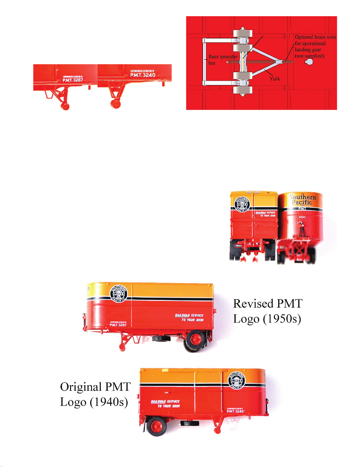
Included in your kit is enough material to construct two trailers, including decals to model a variety of Daylight
PMT equipment. Southern Pacific, Pacific Electric, and Northwestern Pacific owned PMT trailers and we have
accurately researched their trailer logos to include in the decal sheet. Two varieties of Southern Pacific logos
are printed to represent the early and late versions. These decals are available separately from Espee Models.
A variety of parts sprues were tooled to create these highly-accurate trailer models. You will find two of each
sprue; sides, floor/roof/rear door, frame rail, detail, wheel hubs, landing gear, and rubber.
Side Sprue
Floor, Roof, and Rear
Door Sprue
Frame Rail Sprue
Detail Sprue
Wheel Hubs
Landing Gear Sprue
Rubber Sprue
1. To begin, look over each sprue and remove any flashing from the injection process. A new No. 11 blade
can be carefully used to remove flashing. A file may be used, but be careful not to remove paint from the
surface. If needed, the correct matching paint is available from P-B-L, P.O. Box 769, Ukiah, CA 95482,
or call 707-462-7680. Ask for SP Daylight Red and Daylight Orange.
2. Remove sides, roof, frame, and rear door from the sprue using a fresh X-Acto blade. Cut each piece
carefully to avoid damaging the painted surfaces.
3. Place roof upside down on your modeling table. Fit the two side pieces to the roof before gluing to
insure proper fitment. Then glue the side pieces to the roof with liquid cement on the inside of the
trailer. Then fit the frame to the model. Apply liquid cement inside the trailer to secure the frame.
Once the shell of the trailer is dry, you may add weight if you desire (weight not included).
4. Note the rear door is keyed to fit onto the back of the shell. Place liquid cement around the rear surfaces
being careful not to damage the surrounding paint. Place the rear door to the model and let dry.
5. Cut out frame rails from their sprue, but do not attach
them to the trailer frame yet. You will note each frame
rail is keyed specific to the slots in the frame to allow
proper placement. Before inserting the frame rails to the
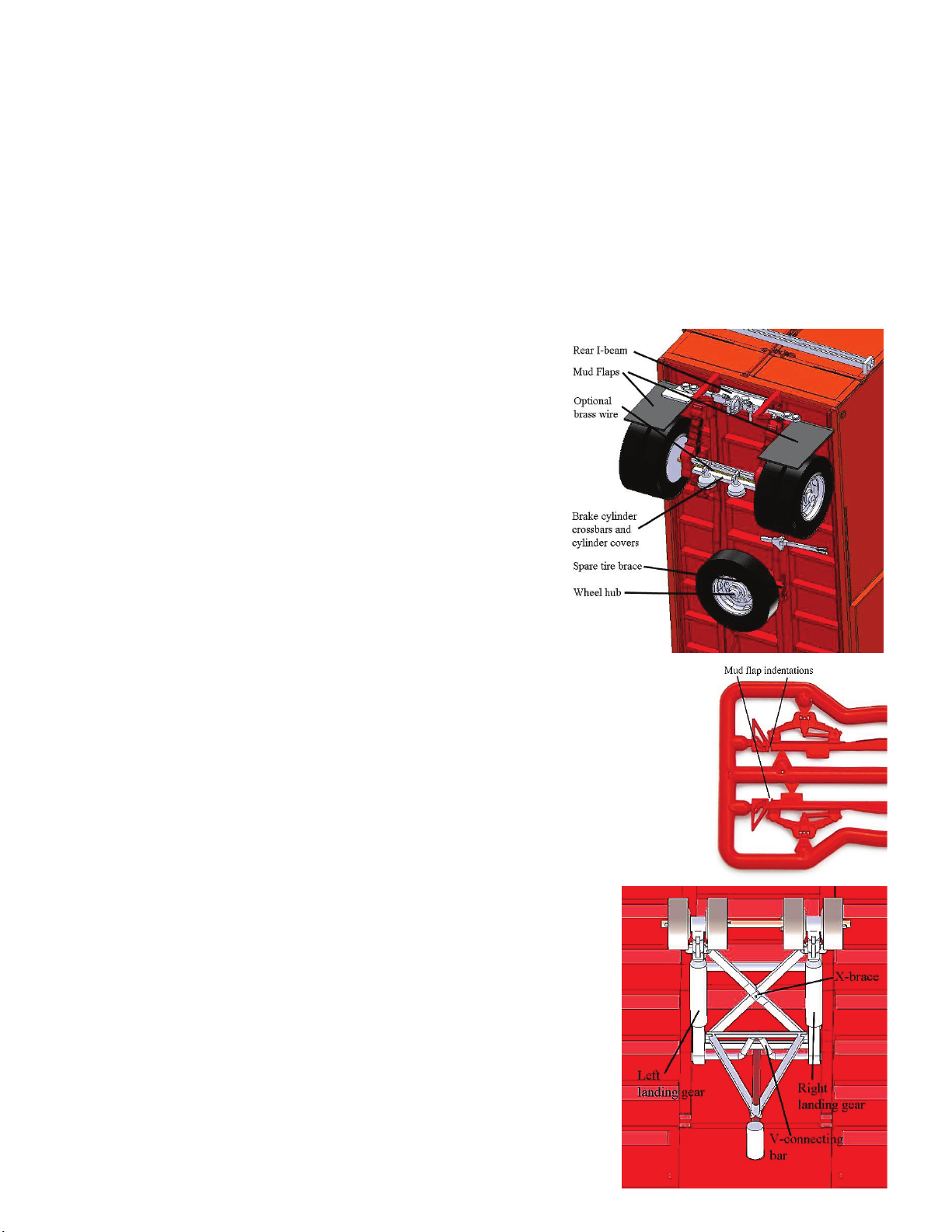
frame, remove the following parts from the detail sprue;
brake actuator covers, brake cylinder front crossbar, brake
cylinder rear crossbar, rear hitch I-beam, and spare tire
brace. Note in assembly that the tip on the brake actuator
covers faces upward toward the brake beam.
6. Glue the brake cylinder front and rear crossbars into one
side of the frame rails. Note the inside of the frame rails
have the slots for detail. Then glue the rear I-beam to the
same frame rail. Note the diamond-shaped detail
represents the electrical conduit cover plate and faces the
rear of the trailer. There are also two nubs on the rear I-
beam that face toward the ground. These will be used
later.
7. Next, glue the other frame rail into each detail part, carefully fitting the two
sides to eachother. Then glue the brake actuator covers onto the cylinders
with the tip facing upwards toward the frame.
8. Remove the mud flaps from the rubber sprue, removing any flashing with
caution because the rubber will slice easily. Now that the frame rails are
partially assembled and ready to be inserted into the frame, note the mud
flap indentations located above the triangular brace. Glue the mud flaps
into the indentations facing down.
9. Glue the frame rails into the frame with the mud flaps attached. Apply
liquid cement to the slots in the frame and the tabs on the frame
rails for a secure joint.
10. Apply the spare tire brace across the two frame rails and glue in
place. Remove the spare tire hub from the wheel spue and glue
on the spare tire brace.
11. You have the option to use brass wire for your wheel axle (not
supplied). At this time, attach the wheel hubs using brass wire or
gluing them to the leaf springs. The locating tab on the wheel hub
faces in the upward position to allow the slotted rubber tires to fit
over the wheel chalks on your Espee Models Piggyback Flatcar
(sold separately).
12. Turn attention to the landing gear sprue and remove the following
parts; right landing gear, left landing gear, yolk, rear spreader bar,
V-connecting bar, and X-brace.
13. At this stage you will need to determine if you
plan to use the landing gear in the upward or
downward position. The landing gear was in the
downward position unless the trailer was
connected to a tractor.
14. Glue the right and left landing gear braces in place with their locating pins in the slots along the frame
rail. Insert the rear spreader bar and V-connecting bar for fitment and glue in place.
15. Attach the X-brace with the cross brace facing upward toward the floor. Glue the yolk to the crossbrace
of the x-brace and to the trailer floor. At this time, shape wire (not included) and glue it through the
yolk and into the frame to represent the rachet guide (optional).
16. Glue the landing gear wheels to the right and left braces. If desired, you may drill through the parts and
connect them with brass wire (not included).
17. Cut out all decals necessary to complete the two trailer
models. Apply decals as appropriate. The images below
represent the typical placement of the black stripe, logos,
and all stenciling. The small version of each logo type is to
be applied on the rear door. Use Solvaset and allow decals
to dry.
18. Your trailers are now ready for the final details. Remove
the following parts from the detail sprue; left turn signal
(includes license plate), right turn signal, tow hitch, and
fifth wheel king pin. Note the king pin is double-ended
and keyed to fit into the frame. If you plan to model your
Downward
Upward
Model photos to scale
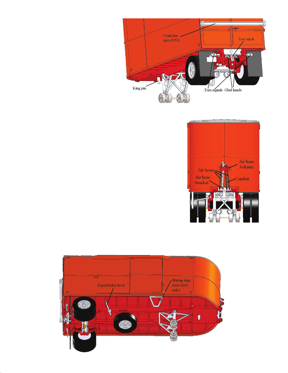
trailers as a load or static display,
the small end of the king pin is
molded in scale. If you plan to use
it behind a tractor, the large end fits
into the Classic Miniatures tractor
available from your local hobby
shop. Glue the king pin.
19. Apply the turn indicators by gluing
them to the top of the triangle
bracket on the frame rails. Decal
the license plate if you desire.
20. Drill a hole into the center of the
rear I-beam and glue the tow hitch
with the shackle facing downward.
21. Crash bars over the rear door of
PMT trailers were eliminated in late 1953 with the
development of improved locking mechanisms. This is an
optional detail depending on the era you’re modeling.
22. Using a knife or fingernail clippers, remove the three air hoses,
electrical conduit, and two small gladhands from the rubber
sprue. Glue the glad hands into the locating tabs on the rear I-
beam.
23. Remove the air hose A-frame and air hose bracket from the
detail sprue. Glue them on the nose as seen in the drawing.
Feed the hoses and conduit through the A-frame and glue the
hoses into the holes in the lower bracket.
24. The hand brake is located on the detail sprue below the crash
bar. Carefully remove it and glue it on top of the frame rail as
shown below.
25. If you have purchased the side-door version of these trailer
models, remove the stirrup step from the detail sprue and
attach it below the door in the notches along the frame.
26. Air brush a clear coat using the finish of your choice.
27. Remove a total of five wheels from the rubber sprue. Note there are four wheels notched to fit over the
wheel chalk if used in piggyback service. Otherwise, use four plain tires and press them onto the wheel
hubs. Press the spare tire onto the spare brace.
© 2014 SPH&TS
Table of contents
Popular Toy manuals by other brands

Step 2
Step 2 Crayola Crayon Rider 8414 quick start guide

Lightmybricks
Lightmybricks LEGO STATUE OF LIBERTY 21042 installation guide

Bojungle
Bojungle B-Joyful Activity Station Pastel manual

V-tech
V-tech Winnie the Pooh Bounce n Learn Honeypot user manual

Step 2
Step 2 TIMELESS TRENDS KITCHEN 4030 manual

Roc Hobby
Roc Hobby F-16 Falcon operating manual

V-tech
V-tech Fly & Learn Airplane user manual

KNEX
KNEX MARIOKART Wii MARIO AND DONKEY KONG CIRCUIT START LINE BUILDING SET... manual

Lightmybricks
Lightmybricks LEGO Corner Garage 10264 manual

V-tech
V-tech 2-in-1 Learn & Zoom Motorbike user manual

MTHTrains
MTHTrains Rail King Imperial Series Operator's manual

Eduard
Eduard MiG-29UB undercarriage quick start guide


