Spice Application Systems SAS DV User manual

-1 -
Spice Application
Systems Ltd
INSTRUCTION MANUAL
ELECTROSTATIC FOOD SPRAY UNIT
MODEL SAS DV
PO Box1190
Oxford
OX4 4GH
England, UK
Tel:- 00 44 18 65 74 76 34
Fax:- 00 44 87 01 60 27 55
E-mail:- [email protected]
Web:- www.spiceapplications.com

-2 -
INDEX
EC DECLARATION OF CONFORMITY FOR MACHINERY ........................................ 3
WARNINGS ................................................................................................ 4
SAFETY GUIDELINES ................................................................................................ 4
TECHNICAL FEATURES ............................................................................................. 5
ELECTRICAL CONTROL UNIT....................................................................................... 6
ELECTROSTATIC GENERATING HEAD ....................................................................... 6
PNEUMATIC CONTROL UNIT........................................................................................ 6
CONTROL UNIT FRONT PANEL.................................................................................... 7
CONTROL UNIT REAR PANEL...................................................................................... 7
MANIFOLD INLET ASSEMBLY ...................................................................................... 8
CONTROL GENERAL ASSEMBLY- FRONT.................................................................. 9
CONTROL GENERAL ASSEMBLY- REAR.................................................................. 10
CONTROL DIMENSIONS11
CONTROL GENERAL ASSEMBLY- PART NUMBERS ............................................... 12
MANIFOLD INLET ASSEMBLY- PART NUMBERS ..................................................... 12
ELECTROSTATIC GENERATING HEAD - DRAWING................................................. 13
MAINS POWER WIRING .............................................................................................. 14
OPERATING PRINCIPLE ............................................................................................. 14
INSTALLATION .............................................................................................. 15
ATOMIZATION .............................................................................................. 16
POWDER FLOW SYSTEM............................................................................................ 16
START UP ............................................................................................ 17
QUALITY ADJUSTMENT.............................................................................................. 17
CLEANING ............................................................................................ 18
CLEANING PROCEDURE............................................................................................. 18
SERVICING .............................................................................................. 19
SHUTTING DOWN .............................................................................................. 19
DAILY CARE ............................................................................................. 19
TROUBLE SHOOTING ............................................................................................ 20
AIR KNIFE PARTS .............................................................................................. 21
STATIC ELECTRICITY TESTER................................................................................... 22
REMOTE TRIGGER WIRING DIAGRAM ...................................................................... 23
SYSTEM PICTURE .............................................................................................. 24

-3 -
Dear Customer,
Thank you for buying a new ELECTROSTATIC FOOD SPRAY UNIT - model SAS/ DRY/VIBRATOR
every care has been taken, from design to manufacture, to ensure that this product gives you
complete satisfaction.
To obtain the best performance and reliability from this equipment it is strongly recommended to
read the instruction manual thoroughly before attempting to use the equipment.
EC DECLARATION OF CONFORMITY FOR MACHINERY
The manufacturer : Spice Application Systems Ltd.,
PO Box 1190, Oxford, OX4 4GH, England, UK.
Tel: 00 44 11 79 10 23 93
Fax: 00 44 87 01 60 27 55
Herewith declares that “the Electrostatic Food Spray Unit”,is in conformity with the provisions of :
EC Machinery Directive 89/392/EECAnnex II, sub A
EC Low Voltage Directive 73/23/EEC
EC Directive of Electromagnetic Compatibility 89/336/EEC:
EN 50081-1
EN 50082-1
EC Equipment Using Flammable Materials 89/336/EEC
EN50 050:1986
EN50 053:Part 2:1989
All as amended, and with national implementing legislation.
Established in Oxford, on October 1st 1999
Peter King
Managing Director
Warning

-4 -
All controls within the Control Box have been adjusted for optimum performance and
safety during manufacturing.
The Electrostatic Generating head is sealed for IP 65.
Re-adjustments, alterations or substitutions of any component may result in a hazardous
operating condition a failure and possible damage to the equipment as well as over –riding
the built in safety features.
Any unauthorized modification will invalidate the warranty and could endanger the work
force.
Under no circumstances are any alterations allowed to the electrostatic equipment without
specific written instructions and consent from Spice Application Systems Ltd.,
SAFETY GUIDELINES
The person in charge of the Manufacturing work area should ensure that personnel are
properly trained in the use of this equipment. The safety rules which follow should be fully
understood and applied at all times.
Never point the spray unit at any person or animal.
Spraying certain products can be dangerous, depending on what is being sprayed so full
protection for operators in the form of instructions supplied with that product must be
adhered to at all times.
The normal safety rules and precautions for powder atomisation must be observed.
For more information, consult the local safety rules. In addition, the following precautions must
be observed.
WARNING ! Failure to observe one of the following rules may affect the operation of
the equipment and create unsafe conditions.
ALL personnel who are associated with the coating operation should read and fully
understand this manual. It is especially important that the operators of the
electrostatic equipment and their supervisory personnel understand the requirements
for safe and proper usage of the electrostatic process.

-5 -
TECHNICAL FEATURES
The SAS/DRY/VIBRATOR spray unit uses the principal of atomising the spice as it falls off
the vibrator by spraying air and electrical charge onto the powder, it is able to obtain the
ultimate wrap-around effect, onto a grounded product.
An electronic safety device, incorporated into the SAS power supply unit, automatically
detects the presence of a grounded object in the vicinity of the spray head. Once this
ground approaches within 10 cm / 4" this device reduces the voltage.
Pressure/Connections :
Control air out ......................... polyamide hose Ø 6 x 8mm
Control air in............................ polyamide hose Ø 8 x 10mm
The pneumatic system to provide clean, dry, oil free food quality
compressed air a minimum pressure of 4 bar / 58 psi
Electrical features Ionization…….Negative charge on the electrode.
Weight : Total weight with BG (without cable or hose) : 1.25kg / 2.75 lb
Stainless Steel Food Quality 316/304
Plastics Polypropylene Co Polymer-Nat
Acetal Co Polymer-White
Cable Polyurethane-Black (Special design for SAS)
Cable Gland Polymide-Light Grey
ELECTRICAL - CONTROL UNIT

-6 -
Mains Electrical Supply - Single Phase 3 Wire (Live-Neutral-Earth)
Supply Voltage - 90 – 264V a.c.
Supply Frequency - 47 – 64 Hz
Connected Load - 40 VA
Circuit Protection - 0.6 A Miniature Circuit Breakers – Live & Neutral
No. of Outputs to Applicators - 1 or 2 Applicators
Output Voltage to Applicators - 3.5 – 13V d.c.
Output Current to Applicators - 400mA Max
Protection Category - IP 54 (IP 67 when fitted into an SAS designed cabinet)
Operating Temperature - -10ºC/+60ºC
ELECTROSTATIC GENERATING HEAD
Supply Voltage - 3.5 – 13V dc
Supply Current - 400mA Max
Output Voltage - 20-85kV
Output Current - 50uA Max
Protection Category - 1P 67
Operating Temperatures - -10ºC/+60ºC
PNEUMATIC – CONTROL UNIT
Compressed Air Supply - 8 Bar (114psi) Max / 5 Bar (75 psi) Min
Compressed Air Consumption - 10m³/hr (6 c.f.m) per Applicator
Max Water Vapour Content - 1.3g/m³
Max Oil Vapour Content - 0.1 p.p.m.
Regulated Air Output - 0-4 Bar

-7 -
CONTROL UNIT REAR PANEL
CONTROL UNIT FRONT PANEL
1
1
2
2
0.6A 0.6A
1 2
MADE IN
INPUT:90-264V 47-63Hz 45W
MAX.OUTPUT:15V.650mA.-ve.
NEGATIVE AIR IN: 7 Bar Ma x.
WARNING
THIS EQUIPMENT
MUST BE E ARTHED
ENGLAND
S.A.S. TYPE SAM2
Serial No.
PART No.2025002
+
_
1 2 S.A.S
psi
bar psi
bar
+
_
12
2
15
3
14 15
16 1312 10
11
2
15
3
14 15
16 1312 10
11

-8 -
SAS Manifold Inlet Assembly
1
2
3
4
5
6
28
2
4

-9 -
1
2
3
5
7
9
10
8
11
14
SAS GCU General Assembly - Front

- 10 -
4
61
2
8
9
10
11
12
13
7
14
15
16
17
SAS GCU General Assembly - Back

- 11 -
SAS GCU Overall Dimensions

- 12 -
Spice Application Systems
Gun Control Unit General Assembly
Part No. 2025030
Item Part No. Description Qty.
1 2020023 0-4 Pressure Gauge with Black Bezel 2
2 2025021 Pressure Regulator 4 Bar Assembly 2
3 9001797 Switch Front 22.5mm 1
4 9001798 Contact Assembly 22.5mm 1
5 9001799 Switch Front 16mm 2
6 9001800 Contact Assembly 16mm 2
7 9001768 Power Supply Unit SSL 40-7624 1
82025005 PCB Assembly 2
9 2025004 Inlet Manifold Assembly 2
10 9001758 Swivel Elbow, 8mm 4
11 9000016 Circuit Breaker, 0.6A 2
12 9001508 Straight, 1/4 BSPMT - 10mm OD Tube PI 1
13 9000021 Terminal, Earth Post 1
14 9000012 Connector Socket Insert 3 PIN + E 1 (2)
15 9000011 Connector Plug Insert, 3 PIN + E 1
16 9000013 Connector Socket Insert 4 PIN + E 2
17 2025010 SAS Case 1
18 2025012 SAS Lid * 1
* Not shown on this illustration
Spice Application Systems
Inlet Manifold Assembly
Part No. 2025004
Item Part No. Description Qty.
1 2025015 SAS Inlet Manifold 1
2 9000038 Valve, Solenoid, 2-2 3/8 BSP, 24V.DC 2
3 9001531 Banjo Bolt 3/8" BSP Single 4
4 9000042 Washer, Sealing, 3/8 BSP, Nylon 8
5 9001794 Banjo Body 8mm 2
6 9000034 Blank, 1/8 BSPMT, Hex SKT 1

- 13 -
NOZZLE ASSEMBLY, Part No. 3025004
5. HOSE LOCKING RING, Part No. 3025012
BODY ASSEMBLY
Part No. 3025003
NOZZLE LOCK NUT ASSEMBLY, Part No. 3025006:
1. NOZZLE LOCK NUT
2. O-RING BS127, WHITE, Part No. 9001805
3. O-RING BS129, RED, Part No. 9001806
3
2
1
55
305
4 5
4. NOZZLE, Part No. 3025011
Ø20 MOUNTING SPIGOT
HOLE FOR M8 BOLT TO MATING CLAMP.
(MATING CLAMP TO SUIT APPLICATION)
120

- 14 -
IMPORTANT
When fitting a plug to the mains lead it is essential that it contains an
earthing/grounding contact and that this is connected. Under no circumstances
should this equipment be connected to a mains supply which does not include an
earthing/grounding wire and contacts. e.g.. 2 –Wire extension leads as used for some
domestic equipment MUST NOT BE USED.
NOTE:- The cable colour coding used for the Control Unit and its supplied mains cable is as
follows:-
Pole US/JAPAN U.K.
Live LBlack Brown
Neutral NWhite Blue
Earth / Ground EGreen Green/Yellow
For U.K. Equipment:
The wire which is colouredGREEN and YELLOW must be connected to the terminal in the
plug which is marked with the letter Eor by the earth symbol, or coloured green or green and
yellow. The wire which is coloured BLUEmust be connected to the terminal which is marked
with the letter Nor coloured black. The wire which is coloured BROWN must be connected to
the terminal which is marked with the letter Lor coloured red.
NOTE:-
The terminals used in the mains connector on the control panel of the unit are:-
POLE PIN No.
Live Pin 1
Neutral Pin 3
Earth / Ground Pin E
The method of disconnection from the mains electrical supply is by removal of the mains lead
plug from its respective supply socket.
OPERATING PRINCIPLE
The SAS control power supply transforms the 110/220 Vac into an adjustable voltage
which can be set from 3.5 to 13 Vdc.
The generator at the spray head converts the 12 Vdc into 85 kV negative charge, the
material being applied is drawn to the positively grounded product.

- 15 -
INSTALLATION
1. For full and perfect performance the drum will require at least 6 horizontal flights and
diameter of at least 0.750 mtr.
2. The vibratory powder transfer unit needs to be positioned just below the screw feeder
and the spray head needs to be positioned inside the drum facing the tumbling product
at a 45º angle.
3. The vibratory system is delivered with a support bar and fixings to allow adjustment for
the correct positioning of the vibratory tray (See attached photograph, page24)
4. The electrode needle on the spray head must always be pointing away from the
vibratory tray
5. The vibrator control needs to be fitted close to the vibrator to allow operators to adjust
the vibration speed. If the vibrator control has to be moved to a fixing further away than
the standard distance of 1.5mtrs (6’) a junction box has to be fitted to a rating of IP 67.
Contact Spice Application Systems Ltd. for this fitting
6. The Spray Head is delivered already attached to the vibratory unit.
7. The product to be coated must be able to fully tumble and roll in front of the spray
pattern. If it does not do so the electrostatic effect will not activate properly and will give
a poor quality finish to the product.
8. The appropriate distance between the spray head air knive and the product to be coated
to be of about 20 - 45 cm / 8" - 18" (minimum distance is 15 cm / 6").
9. The control unit must be located outside the flavouring drum.
10. All metal parts, pumps, containers, conveyors (feeding in and out of the drum)
and any other conductive article within 2mtrs/ 6ft - must be grounded.
11. Keep the spraying area clean. Remove all unnecessary metal components.
12. After fixing the the electrostatic generating head in place inside the drum. Fix the black
cable with plug attached to the back of the control attachment, to electrical plug maked
“1” and lock into place. (Locking mechanism already attached to control) If using a twin
head system attach both black cables, first to “1” and the second to “2” . [see control
drawings under page 7 Item 16]
13. After fixing the electrostatic generating head in place inside the drum. Fix the 8mm air
line to the bottom air fittings on the back of the control to fitting “1” Push in firmly. If
using a twin head system attach both 8mm air lines, first to bottom air fitting “1” and the
second to bottom air fitting “2” . [see control drawings under page 7 Item 10] The other
end of the air lines attached to the air fittings on the air knive under the vibratory tray.

- 16 -
14. The two upper air fittings on the control are for blowing down the line for cleaning during
spice change. The control is delivered with blank off plugs fitted. Remove a blank off
plug and insert the 8mm air line (Push in firmly) which is attached to the blow down gun.
15. Plug into rear of control (Item.12) a 10mm air line from the main air supply.(The air
always has to be clean and dry. Fit a filter if necessary)
16. Plug mains electric supply into back of control (Item 14) and lock into position. When
wiring up the mains supply the earth must be wired to the factory mains earthing
system.
17. Item 15 at the back of the control is for a remote trigger for tuning the unit to switch on
and off with an existing production line. If not using, make sure the dust cap is fitted and
locked into place.
18. Wire the earthing cables from the drum to the earthing point at the rear of the control.
Item 13.
19. The drum must be earthed in 2 places. With the earthing contacts rubbing against the
wall of the drum. The out going and incoming vibratory conveyors to and from the drum
must always be earthed.
ATOMIZATION
1 - The part to be coated must be connected to the ground continuously.
2 - Keep the air knive perfectly clean.
3 - Do not use the equipment if there is an air leak in the hoses.
4 - Be sure that the product does not come closer than 15 cm / 6" and no further than
45cm/18” from the spray head.
5 - Before plugging in the power supply unit, be certain the electrostatic generating unit’s air
knive nozzel is installed correctly. The flat jet has to be horrizontal.

- 17 -
POWDER FLOW SYSTEM
1 - Position the vibratory tray under the screw feeder (using an addaptor if required), it
must be aligned correctly to allow the powder to fall into the vibratory tray
2 - Position the vibratory unit at about a 45 angle to the product
3 - The vibratory system need not be moved for cleaning. The system is IP65
4 - The system must be set-up to freely transport the powder throughput from the
screw feeder at the maximum line rate, i.e. Set the air pressure at the electrode air
knive (1.0 - 1.5bar) as if the plant is at maximum production.
START UP
ELECTROSTATIC CIRCUIT
1 - Connect the SAS/Dry control to its power source
2 - Supply the SAS/Dry control with clean dry compressed air (P = 4 bar / 58 psi)
3 - Turn the power-supply ON/OFF switch to the ON position (Item 3)to ON position (Item 5)
4The power supply emits a constant voltage at any given setting from 3,5 to 13 Vdc. This
regulated voltage is transformed into high voltage within the generator barrel before being
delivered to the spray head
5Turn the vibrator control to ON position
QUALITY ADJUSTMENT
Adjust the spraying parameters ON THE FRONT OF THE CONTROL:
-Material flow rate (Pressure regulator Item 1) Adjust by turning clock wise for
more air anti-clockwise for less air. Push in to lock, pull out to unlock (Item 2)
-Electrostatic effect (High voltage is on.Yellow light glowing).
-ON THE FRONT OF THE VIBRATOR CONTROL Adjust the vibrator speed to
when the powder is coating the bed of the vibratory tray. This will give an even
curtain drop onto the air knife
The air hoses and the generating head must remain dry.
The electrostatic efficiency decreases quickly when spray head and hoses are dirty or
damp, this will lead to poor quality finished product.

- 18 -
CLEANING METHOD
The ON/OFF switches on the power supply and to the spray head must be OFF
before starting cleaning opération.
Wait for 10 seconds before entering the drum
All metallic parts located within and around the spray head must be correctly
connected to the ground. The floor must be electrically conductive and grounded.
Only apply a moderate amount of cleaning solution onto a clean soft cloth or bristle
brush to clean the spray head and hoses.
Synthetic resins used in the fabrication of the electrostatic spray head can react
with certain cleaning agents. Check with SAS .
CAUTION : avoid using the most toxic cleaning agents. Do not use chlorinates.
Dry the spray head carefully and thoroughly with air.
PROCEDURE
1 - Turn the power supply ON/OFF switch to OFF position.
2 - Hose down the complete vibratory system in place (CIP). There is no need to remove the
system for cleaning
3 - Wash thoroughly and dry completely with compressed air before commencing production.
(THIS IS VERY IMPORTANT IF THE UNIT IS NOT DRY IT CAN LEAD TO POWDER
BUILD UP ON THE VIBRATOR)
Warning : Never switch ON the Electric power supply unit during the washing and
cleaning operation.
Before switching ON the electrostatic effect :
-Install the air knive into the electrostatic generating head making sure it is set
horizontal - Connect the flexible air tube to the air knive
- Check that the air knive and vibrator are completely dry

- 19 -
SERVICING
1 - The electric power supply must be interrupted before any cleaning operation (power
supply unit switched OFF).
2 - When shutting off the voltage, wait for some 10 seconds so that the electric charge
has time to reach the ground.
3 - Do not soak or immerse the spray unit or any plastic parts in a solvent. This could result
in damage and impair the safety circuits. If necessary, clean the plastic parts with a soft
brush soaked in a soapy water solution after hosing down and then dry immediately.
4 - Before disconnecting hoses, ensure that the circuit is no longer pressurized, the
air is turned off, and that the electric current is also switched off.
5 - After any repair - prior to turning on the power supply –
The air knive is correctly installed into the spray unit.
Re-connect the three pin plug and cable assembly to the power source.
Re-connect the ground wire to an earth connection.
Re-connect low voltage cable between SAS control and electrostatic generator head
EXTENDED SHUT-DOWN PERIOD
1 - TURN THE ON/OFF SWITCH ON THE POWER SUPPLY TO THE OFF POSITION.
2 - Carry out a complete flushing of the system. Carefully clean the spray head with a
solution soaked rag or bristle brush.
3 - Dry the clean parts with compressed air. Be sure the air spray nozzle is clean.
NEVER LEAVE ASSEMBLY AND SPRAY HEAD IMMERSED IN CLEANING
SOLUTION. ALWAYS STORE IN A DRY PLACE.
NEVER USE METAL TOOLS TO CLEAN THE SPRAY HEAD.
DAILY CARE
1 -air knive and vibrator are kept clean,
2 -all hoses are not worn or crimped, all air and coating material connections are tight,
3 - all electrical cables are not brocken or knotted
4 - all earthing wires on the in/outgoing vibratory trays and the drum are connected correctly.

- 20 -
TROUBLE SHOOTING
Unit will not operate :
1. Mains connector not fitted to control panel :
Connect to the rear of control panel (page 7 Item 15 )
2. Not connected to a suitable mains electrical supply :
Engineer to check supply
3. Not switched on :
Turn the switch on at the front of the control panel (page 7 Items 3 & 5)
4. Circuit breakers tripped at the rear of the control panel :
Press circuit breakers inwards. If they trip out again after turning on the unit call for an
engineer
Spitting Spray:
1.Insufficient air pressure:
Turn up the air pressure
Check hoses for leaks and tighten fittings
2. Empty powder hopper in the screw feeder:
Fill the hopper
No powder delivery:
1. Screw feeder Blocked:
Empty screw feeder, remove screws and clean thoroughly
Re-assemble and re-fill hopper
2. Insufficient air pressure to the air spray head:
Increase air pressure at the control
1. Pinched or restricted air lines:
Check and replace if necessary
2. No powder in the screw feeder:
Fill the screw feeder hopper
3. Vibratory tray not working:
Turn on vibrator at the vibrator control
Poor atomisation of powder:
1. Air nozzle obstructed or worn down:
Clean nozzle or replace with new
2. Low air pressure:
Increase air pressure
Powder spraying, poor adhesion to product:
1. Voltage output too low:
Adjust the vibratory tray further away from the product
2. Earthing not correct:
Re-set the earth wiring and contacts
3. Spice not suitable for electrostatic application:
Contact spice supplier
4. Spice particles too large:
Contact spice supplier
Table of contents
Other Spice Application Systems Paint Sprayer manuals
Popular Paint Sprayer manuals by other brands

RIGO
RIGO LVLP PRO AXV Use and maintenance manual

NEW BRUNSWICK SCIENTIFIC
NEW BRUNSWICK SCIENTIFIC innOva 4200 Guide to Operation

Westfalia
Westfalia 85 92 78 Original instructions
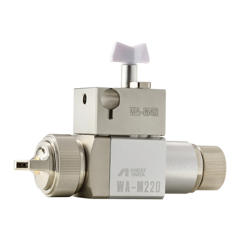
Anest Iwata
Anest Iwata WA-M220 Use and maintenance instruction manual

Graco
Graco Idler 257817 quick start guide

Cima
Cima BLITZ 45T Instructions for use and maintenance
