Spicer DSSM0100 User manual

Spicer®Driveshafts
Service Manual
DSSM0100
December 2010
Spicer®Life Series

i
Table of Contents
Inspection Procedures
Inspection Warnings and Cautions . . . . . . . . . . . . .. . . . .1
Universal Joints . . . .. . . . . . .. . . . . . .. . . . . . . . . . . . . . .4
Slip Member Assembly . . . . . . . . . . . . . . . . . . . . . . . . . . .5
Tubing Inspection . . . . . . . . . . . ... . .. . ... . .. . . . . . . .7
Center Bearings . . . . . . . . . . . . . . . . . . . . . . . . . . . . . . . . .7
Lubrication
Warnings and Cautions . .. . . . . ... . . . . . . . . . . . . . . . . .8
Recommended Lubricants for Relubable Universal Joints and
Slip Members . .. . . . . . . . . .. . . . . . .. . ... . .. . . . . . . .9
Grease Compatibility . . . . . . . . . . . . . . . . . . . . . . . . . . . . .9
Universal Joints . . . . . . . .. . . . . . . . . .. . . . . . . . . . . . . .10
Slip Joint . . . . . . . . . . . . . . . . . . . . . . . . . . . . . . . . . . . . .12
Center Bearings . . . . . . . . . . . . . . . . . . . . . . . . . . . .. . . .13
Removal
Warnings and Cautions . .. . . . . ... . . . . . . . . . . . . . . . .14
Driveshaft Assemblies . . . . . . . . . . . . . . . . . . . . . . . . . . .15
Grease Zerk Removal and Installation . . . . . . . . . . . . . . .16
Slip Member Boot . . . . . . . . . . . . . . . . . . . . . . . . . . . . . .18
Center Bearing . . . . . . . . . . . . . . . . . . . . . . . . . . . . . . . . .19
Installation
Warnings and Cautions . .. . . . . ... . . . . . . . . . . . . . . . .21
Universal Joint - Snap-Ring Style. . . . . . . . . . . .. . .. . . .22
Universal Joint - Spring Tab Style . . . . . . . . . . .. . .. . . .24
Center Bearing . . . . . . . . . . . . . . . . . . . . . . . . . . . . . . . . .25
Slip Member and Boot . . .. . . . . . . . . . . . . . . . . . . . . . . .26
Driveshaft . . . . . . . . . . . . . . . . . . . . . . . . . . . . . . . . . . . .27
Glossary
Glossary . . . . . . . . . . . . . . . . . . . . . . . . . . . . . . . . . . . . . .29
Appendix . . . . . .. . .. . . . . . . . . . . . . .. . . . . . .. . .. . . .32
For additional service information, go to www.dana.com or
call 1-877-777-5360.

ii
General Information
General Information
General Information
Spicer Life Series™ Features and Benefits
Note: Spicer Life Series™ driveshafts are found on vehicles
throughout the world. Therefore, this manual includes
worldwide terminology.
This manual encompasses inspection, lubrication, removal
and installation procedures for Spicer Life Series™ 55, 70, 90,
100, 140, 170 and 250 driveshaft assemblies.
Important Features of a Spicer Life
Series™ Driveshaft
Spicer offers a complete range of driveshaft solutions to meet
the full spectrum of needs in medium and heavy duty applica-
tions. The Spicer Life Series™ driveshafts have been designed
and developed to stand up to the wear and tear of heavy haul-
ing tasks. They are the first driveshafts in the industry to be
compatible with advancing powertrain specifications for
higher engine torque and lower axle ratios. No one does more
than Spicer in meeting the needs of the marketplace.
Spicer Life Series™ driveshafts offer:
• Longer life
• Lower lifetime management
• Increased strength for higher engine torque and
lower axle ratios
• Smaller driveshaft rotating diameter
A driveshaft that transmits high torque loads must be durable
and strong. Spicer uses forged steel and high strength cast
yokes to provide the necessary rigidity to maintain bearing
alignment under torque loads. Spicer Life Series Quick Dis-
connect™ end yokes reduce the time to remove or install the
driveshaft, equating up to a 75% labor savings for service.
Applications requiring flange connections, S.A.E., DIN and
cross-serrated T-Flanges are available. A new cold-formed,
bearing retainer provides structural rigidity and reduces bear-
ing movement which may result from overloading.
Spicer Life Series™ award winning* universal joint kits are
specifically designed to give extended driveshaft life. Flat-
ended needle bearings are used to withstand oscillating loads
while the driveshaft is rotating and to eliminate skewing in the
bearing cup. Thrust washers significantly reduce end galling
on trunnion ends and lower universal joint operating tempera-
ture. Synthetic rubber seals and plastic seal guards provide
lubricant retention and help prevent the entry of foreign mate-
rial, significantly increasing universal joint life. The centrally
located grease zerk (nipple) fitting increases the strength of
the journal cross and allows more torque carrying capacity.
High-strength steel tubing is used to provide maximum
torque carrying capacity at minimum practical weight.
Increased tube diameter allows a higher critical speed and
longer one-piece driveshafts. This increased stiffness also
improves noise, vibration and harshness. New slip member
booting or alternative seal can offers better protection against
environmental contaminants, increases component life, and is
lubricated for the life of the product.
The new integral tube sleeve and yoke shaft design, found on
heavy duty Spicer Life Series™ designs, along with larger
diameter involute splines, creates greater strength and tor-
sional stiffness with less weight. This new design leads to
improved balance and less slip effort, resulting in reduced
noise and vibration for the entire driveshaft system. Spicer
Glidecote®, found in all slip member assemblies, reduces
friction, thereby lowering thrust loads under high torque. This
nylon coating also prevents spline wear and extends life.

1
Warnings and Cautions
Spicer Life Series™ Inspection Warnings and Cautions
Before You Get Started
1. ALWAYS wear safety glasses when performing
maintenance or service. Failure to wear safety
glasses can result in personal injury and/or partial or
complete vision loss.
2. NEVER go under a vehicle while the engine is run-
ning. Be sure the vehicle's engine is off, and keys are
removed from ignition.
3. NEVER go under or work on a vehicle that is not on a
level or flat surface.
4. NEVER work on a driveshaft without blocking the
vehicle's wheels and releasing all parking brakes.
See warning below.
5. NEVER lift a vehicle without the appropriate weight-
rated, vehicle-support equipment.
6. NEVER REMOVE a driveshaft from the vehicle with-
out keeping the vehicle's transmission in neutral.
See above warning.
7. CAUTION – Spicer Life Series™ driveshaft assem-
blies can weigh in excess of 100 pounds (46 kilo-
grams). Be sure to use proper lifting techniques
when handling Spicer Life Series™ driveshafts. More
than one person may be needed when handling
driveshaft assemblies.
8. ALWAYS use support straps to prevent the drive-
shaft from falling, causing injury and/or damage dur-
ing the loosening or removal of any driveshaft
hardware.
9. NEVER heat components or use sledgehammers or
floor jacks to remove the driveshaft from vehicle.
Note: For driveshaft applications that have pillow blocks,
dampers, parking brakes or retarders, refer to these
component manufacturers' or the original equipment
vehicle manufacturers' service manuals for proper pro-
cedures.
Driveline
WARNING: Failure to replace damaged driveline components
can cause driveline failure, which can result in separation of
the driveline from the vehicle. A separated driveline can result
in property damage, serious personal injury, or death.
WARNING: Reassembly of a driveline out of original phase
can cause vibration and failure of the drivline and attaching
components.
WARNING: Driveshaft assemblies can weigh in excess of 100
pounds(46 kilograms). Be sure to use proper lifting tech-
niques when handling driveshafts. More than one person
may be needed when handling driveshaft assemblies.
WARNING: Never heat components, never use sledge ham-
mers, and never use floor jacks to disassemble driveshafts.
This can result in damaged, weekened, or bent components.
End Fitting
WARNING: A loose end-fitting can result in driveline failure,
which can in turn lead to separation of the driveline from the
vehicle. A separated driveline can lead to property damage,
serious personal injury, or death.
Universal Joint
WARNING: Excessive looseness across the end of universal
joint bearing cup assemblies can cause imbalance or vibration
in the driveshaft assembly. Imbalance or vibration can cause
component wear, which can result in separation of the driv-
line.
WARNING: DO NOT reuse bolts or use inferior grade bolts.
Reuse of bolts and/or use of inferior bolts can cause driveline
failure, which can result in separation of the drivline from the
vehicle.
WARNING: Failure to torque bolts to specification can cause
driveline failure, which can result in separation of the driveline
from the vehicle.
CAUTION: Use a journal locator to avoid nicking journal cross
trunnions or damaging oil seal slingers.
CAUTION: If a bearing assembly or journal cross is worn or
damaged, the universal joint assembly must be replaced.
CAUTION: Be sure the snap rings are properly seated in the
snap ring grooves.
WARNING
WARNING
WARNING
2
Warnings and Cautions
Warnings and Cautions
Slip Member
WARNING: Excessive radial looseness in the slip member
assembly can cause imbalance or vibration in the driveshaft.
Imbalance or vibration can cause components to wear, which
in turn can result in separation of the driveline from the vehi-
cle. A separated driveline can cause property damage, seri-
ous personal injury or death.
Yoke (Includes Slip Yoke, Yoke Shaft, and
Tube Yoke)
WARNING: A loose or damaged slip yoke seal allows contam-
inants to invade the slip member assembly. Invasion of con-
taminants into the slip member assembly can degrade the
grease, and damage slip member components, which can
result in driveline separation.
WARNING: DO NOT deform yoke cross holes by removing
excessive metal. Raised metal or deformed yoke cross holes
can be a cause of cross and bearing failure, which can result
in separation of driveline from the vehicle.
WARNING: Yoke shaft assemblies can weigh in excess of 50
pounds (23 kilograms). Be sure to use proper lifting tech-
niques when handling yoke shafts.
Tubing
WARNING: Bent or dented tubing can cause imbalance or
vibration in the driveshaft assembly. Imbalance or vibration
can cause component wear, which can result in separation of
the driveline from the vehicle.
CAUTION: Do not bend or dent the tube when handling or
servicing driveshaft.
Midship Nut
WARNING: DO NOT reuse the midship nut. Reuse of the
midship nut can cause driveline failure, which can result in
separation of the driveline from the vehicle.
WARNING: DO NOT touch or disturb the micro-encapsulated
adhesive found on the midship nut threads. Doing so may ini-
tiate the curing process and impair the installation of the nut.
Premature curing of the micro-encapsulated adhesive will
result in improper installation of the midship nut. Improper
instsallation of this nut can cause driveline failure, which can
result in separation of the driveline from the vehicle.
WARNING: Failure to torque the midship nut to required
specifications can cause driveline failure, which can result in
separation of the driveline from the vehicle.
WARNING: A loose midship nut can result in driveline failure,
which can result in separation of the driveline from the vehi-
cle.
Center Bearing
WARNING: Loose center bearing bracket bolts can result in
driveline failure, which can result in separation of the driveline
from the vehicle.
WARNING: Damaged center bearings or center bearing com-
ponents can cause imbalance or vibration in the driveshaft
assembly. Imbalance or vibration can cause component
wear, which can result in separation of the driveline from the
vehicle.
Foreign Material
WARNING: Build-up of foreign material, excessive paint, or
undercoating on a driveshaft can cause imabalnce or vibration
in the driveshft assembly. Imbalance or vibration can cause
component wear, which can result in separation of the drive-
line from the vehicle.
WARNING: A contaminated slip member can result in separa-
tion from the vehicle. A separated driveline can result in prop-
erty damage, serious personal injury or death.
Hardware
WARNING: Loose, missing, or damaged bearing retainers or
stamped straps, retaining bolts, nuts, end fitting tangs, snap
WARNING
WARNING
WARNING
WARNING
WARNING
WARNING

3
Warnings and Cautions
rings, or rotating bearing cups can result in driveline failure.
A separated driveline can lead to property damage, serious
personal injury, or death.
WARNING: DO NOT reuse bolts, straps, nuts, or damaged
bearing retainers or inferior grade bolts. Reuse of bolts,
straps, nuts, or damaged bearing reatiners, or use of inferior
grade bolts can cause driveline failure.
CAUTION: If loosening or removing bolts, always install a
new strap and bolts and torque bolts to specification.
Lubrication
WARNING: A missing, loose, or fractured grease zerk (nip-
ple) fitting or plug eliminates the ability to lubricate the univer-
sal joint. Improper or inadequate lubrication can cause
driveline failure, which can result in separation of the driveline
from the vehicle.
WARNING: Improper lubrication techniques can cause drive-
line failure, which can result in separation of the driveline
from the vehicle.
WARNING: A missing, loose, damaged, or fractured plug or
grease zerk (nipple) fitting can allow contaminants to invade
the universal joint. Invasion of contaminants into the univer-
sal joint can degrade grease and cause universal joint dam-
age, which can result in separation of the driveline from the
vehicle.
WARNING: Incompatible greases that are applied to universal
joints and/or slip members can result in driveline failure and
can result in separation of the driveline from the vehicle.
WARNING: Hand tightening of grease zerk (nipple) fitting or
plugs is NOT recommended. Failure to torque grease zerk
(nipple) fittings to specifications can result in separation of
the driveline from the vehicle.
WARNING: Maximum grease gun pressure should not
exceed 60 psi. Excessive grease gun pressures may cause
seal damage.
CAUTION: In cold temperatures, be sure to drive the vehicle
immediately after lubrication. This activates the slip spline
and removes excess grease. Failure to do so could cause
excess grease to stiffen in the cold weather and force the plug
out. The end of the spline would then be open to collect con-
taminants and cause the spline to wear and/or seize.
CAUTION: All slip yoke and universal joint seals should be
completely purged.
WARNING
4
Inspection Procedures
Inspection Procedures
Inspection Procedures
Visually inspect all input and output end-fitting retaining nuts
or bolts for any gaps between mating surfaces. If gaps are
present, consult transmission, axle or transfer case original
equipment manufacturers' service and maintenance manuals
for proper fastener specifications.
Visually inspect for damaged bearing retainers or stamped
straps, loose bearing retainer bolts or strap bolts, loose com-
panion flange bolts and nuts, loose or missing spring tabs or
spring tab bolts, damaged tangs on end fittings, damaged or
missing snap rings, and rotating bearing cups.
If any of these situations are evident, replacement of the com-
ponents is necessary. Refer to the removal and installation
sections of this manual for proper replacement procedures.
Universal Joints
Note: The following procedures are to be performed prior to
any lubrication of universal joints or slip members. The
addition of lubricant can mask the looseness in a com-
ponet that is beginning to show wear and may be in
need of replacement.
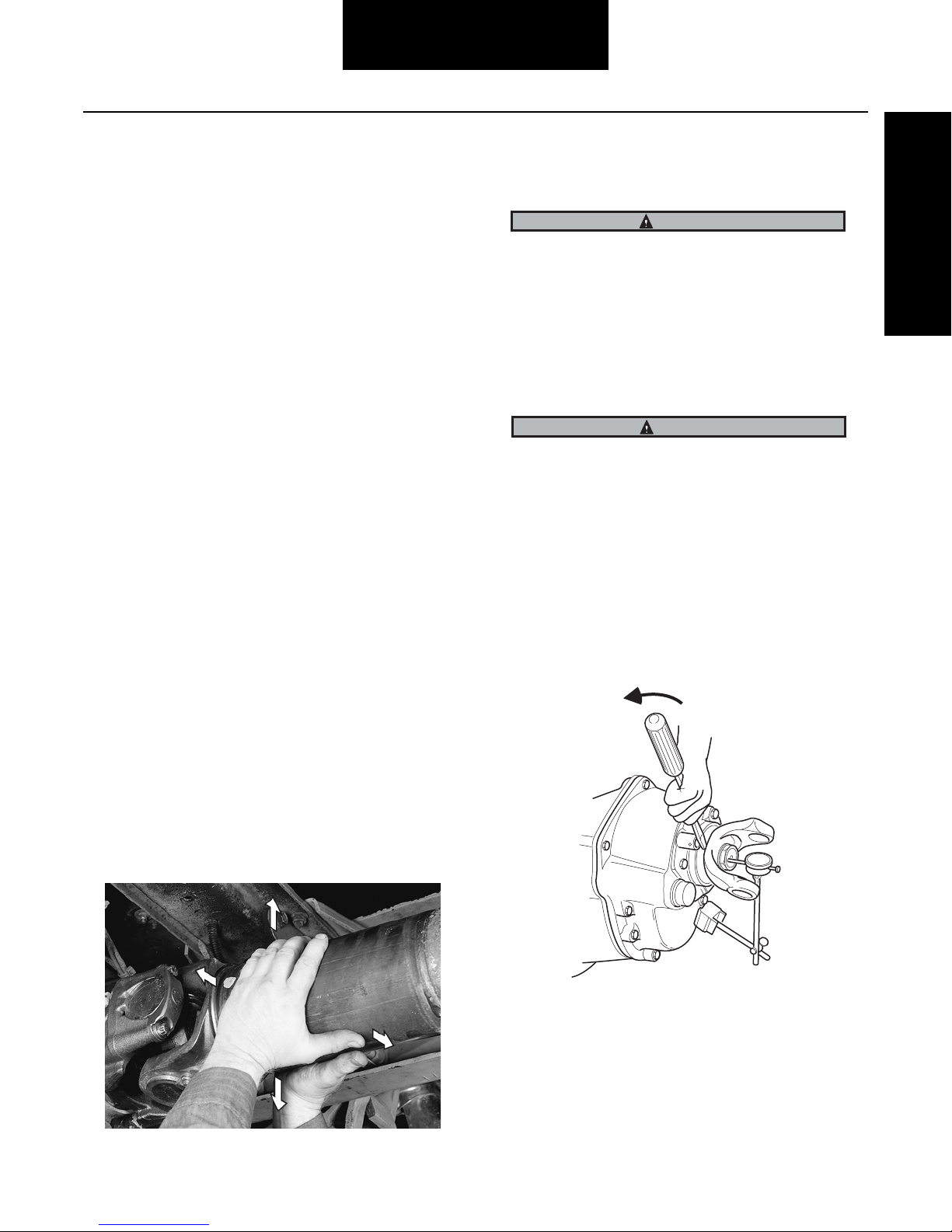
1. Check for excessive looseness across the ends of
the universal joint bearing cup assemblies and trun-
nions. Take hold of the inboard yoke on the drive-
shaft with both hands. Try to move the yoke
vertically and horizontally.
There should be less than .006" (.15mm) movement
in the universal joint relative to the inboard or out-
board yokes. If looseness is greater than .006"
(.15mm), the universal joint kit may need to be
replaced.
Note: If the movement of the driveshaft is greater than .006",
the carrier assemblies input shaft and/or output shaft
ends play must be checked to make sure they are within
specification. Endplay readings that are out of specifica-
tion must be corrected before an accurate driveshaft
reading can be taken. Refer to the Input/Output Shaft
Endplay Inspection procedure.
Excessive looseness across ends of universal joint bearing
cup assemblies can cause imbalance or vibration in the
driveshaft assembly. Imbalance or vibration can cause
component wear, which can result in separation of the driv-
eline from the vehicle.
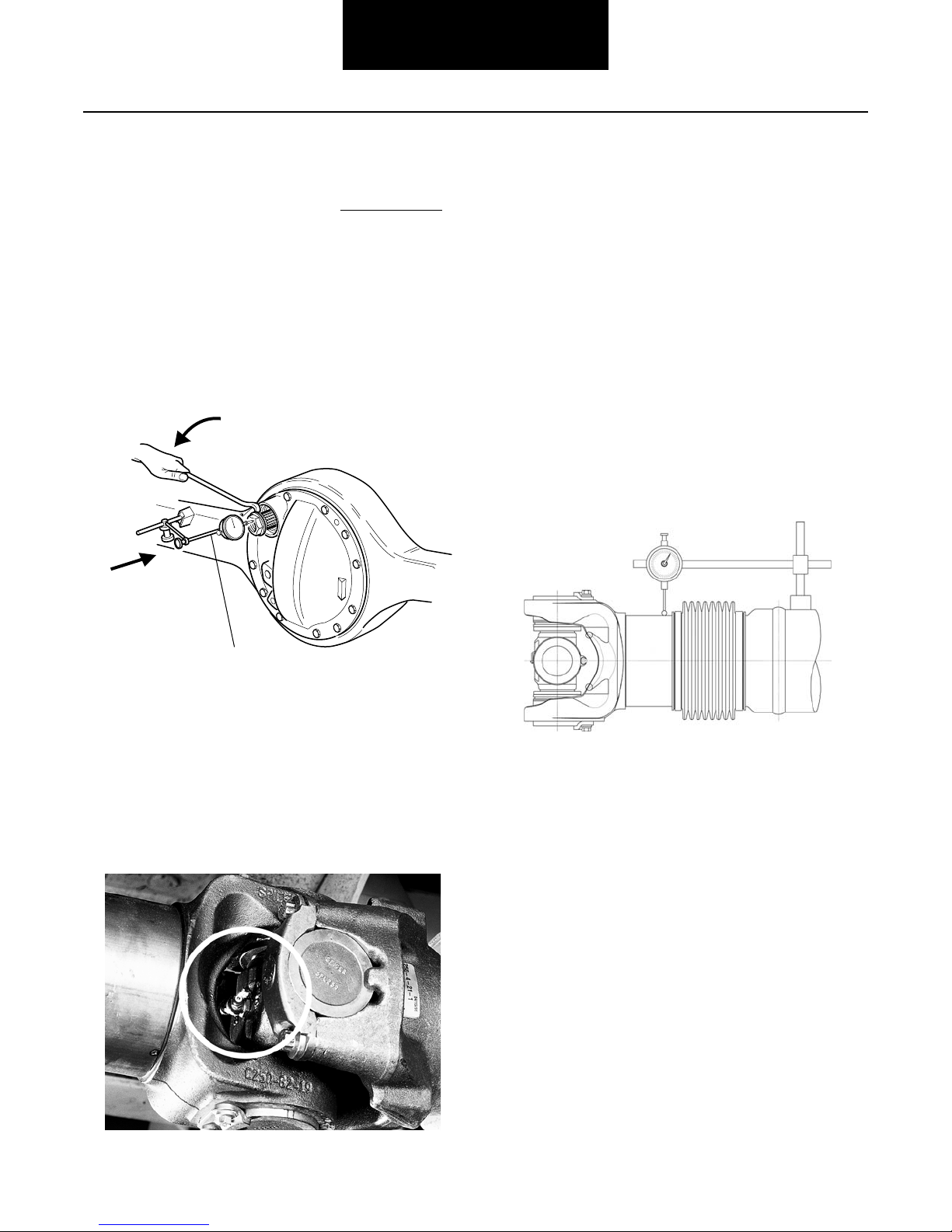
Check Input Shaft End-Play (Forward Axle)
a. Position dial indicator at yoke end of input shaft.
b. Push on input shaft and zero dial indicator.
c. Using pry bar, move input shaft axially and measure/
record end-play.
Add shims to increase end-play.
Note: Input and output shaft endplay specifications will vary
between model. Refer to manufacturer’s service manual
for correct endplay specifications.
IMPORTANT
WARNING
5
Inspection Procedures
Remove shim to decreased end-play.
Check Output Shaft End-Play (Forward Axle)
a. Position dial indicator at yoke end of input shaft.
b. Push on output shaft and zero dial indicator.
c. Using pry bar, move input shaft axially and measure/
record end-play.
Note: The output yoke can be installed when taking end-play
measurements.
d. Correct end-play for new assembly is .001" to .015".
Grease Zerk Inspection
Check for presence of all grease zerk fittings. Grease zerk fit-
tings should not be loose, fractured or missing.
- If grease zerk fitting is loose, tighten to required
specifications.
- If grease zerk fitting is fractured, replace grease zerk
fitting and tighten to required specifications.
- If grease zerk fitting is missing, the entire universal
joint kit needs to be replaced.
- If the plug is loose, tighten to required specifica-
tions.
- If a plug is missing or fractured, the entire universal
joint kit needs to be replaced.
Slip Member Assembly Inspection
1. Check the slip member assembly for excessive radial
looseness. Using a dial indicator, take hold of the
tubing near the slip member with both hands and try
to move vertically, up and down relative to the
ground.
2. Arrange dial indicator with magnetic base one-quar-
ter inch (1/4") from the driveshaft’s tube weld. Dial
indicator should be firmly mounted on the tube so
that no movement of the dial indicator base is
allowed.
3. Extend dial indicator arm from the base, across the
slip member boot, allowing the dial indicator to con-
tact the yoke shaft tube one quarter inch (1/4") off
the opposite side of the boot from where the mag-
netic base is mounted. Dial indicator’s arm should be
running parallel to the driveshaft.
Measured end-play (Step 3) 0.015” – 0.015”
Desired end-play (New Parts) 0.003” to 0.007”
Remove shims to provide desired
end-play
0.012” to 0.008”
1
2
3

6
Inspection Procedures
Inspection Procedures
4. Apply effort perpendicular to shaft axis making note
of total indicator travel. Allowable indicator travel is
.000-.012 in.
Excessive radial looseness can cause imbalance or vibra-
tion in the driveshaft assembly. Imbalance or vibration can
cause component wear, which can result in separation of
the driveline from the vehicle.
5. For an inboard and outboard slip yoke assembly
design, check to be sure the slip yoke welch plug is
not loose, missing or damaged.
If any of these situations are evident, replacement of
the slip yoke and professional rebalancing of the
driveshaft is necessary.
6. Visually inspect for the presence of the grease zerk
fitting, if applicable, on the slip yoke.
a. If grease zerk fitting is loose, tighten to required
specifications. (See Table C.)
b. If grease zerk fitting is missing or fractured, the
slip members may need to be replaced.
7. Check the slip yoke seal. Make sure the seal is prop-
erly attached to the slip yoke and is not loose or
damaged.
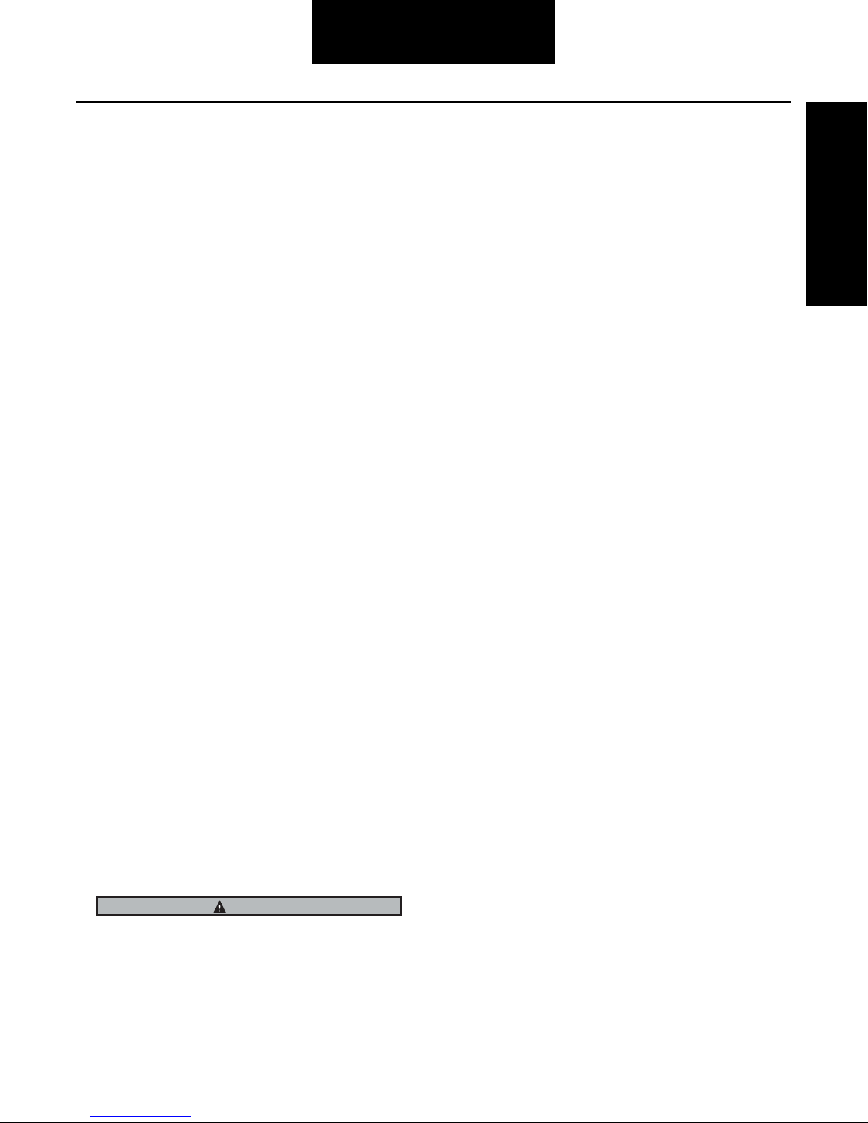
Permanently Lubricated Style
Check the yoke shaft boot. Make sure the boot is properly
attached to the yoke shaft assembly and splined sleeve. Visu-
ally inspect for boot tears, punctures, loose clamps and clamp
damage.
If any of these situations are evident, replace damaged com-
ponents and measure slip joint movement.
WARNING
Table C - Slip Member Grease Zerk Fitting Specifications
Thread
Size
Zerk
Nm
Torque
IN. LB.
0.25"-28" 3.5-6.2 31-55
7
Inspection Procedures
Tubing Inspection
1. Check the driveshaft for bent or dented tubing. If
either of these situations is evident, replacement of
the complete driveshaft assembly or tube is neces-
sary.
2. Make certain there is no buildup of foreign material
on driveshaft.
If found, buildup should be removed carefully to
avoid damaging the driveshaft.
a. When removing dirt or mud, rinse with water.
b. When removing tar or undercoating, use min-
eral spirits or any appropriate solvent.
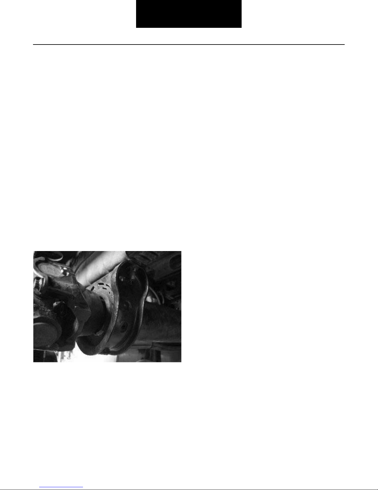
Center Bearings Inspection
1. Visually inspect all center bearings, end-fitting mid-
ship nuts for any gaps between the mating surfaces.
Note: Be sure to repeat steps 2 and 3 for all center bearing
end fittings for broken back and backlash.
2. Inspect the center bearing bracket bolts for loose-
ness.
Note: If looseness is evident, retighten center bearing bracket
bolts. Consult the vehicle manufacturers’ specifications
for proper bolt torque. Check the alignment of the
bracket before tightening the bolts. Bracket should not
be skewed.
3. Visually inspect the center bearing rubber cushion
for damage. Make sure the slingers are not rubbing
against the rubber cushion. Verify that the rubber
cushion is properly seated in the metal bracket.
8
Lubrication Warnings
Lubrication
Spicer Life Series™ Lubrication Warnings and Cautions
Before You Get Started
1. ALWAYS wear safety glasses when performing
maintenance or service. Failure to wear safety
glasses can result in personal injury and/or partial or
complete vision loss.
2. NEVER go under a vehicle while the engine is run-
ning. Be sure the vehicle's engine is off, and keys are
removed from ignition.
3. NEVER go under or work on a vehicle that is not on a
level or flat surface.
4. NEVER work on a driveshaft without blocking the
vehicle's wheels and releasing all parking brakes.
See warning below.
5. NEVER lift a vehicle without the appropriate weight-
rated, vehicle-support equipment.
6. NEVER REMOVE a driveshaft from the vehicle with-
out keeping the vehicle's transmission in neutral.
See above warning.
7. CAUTION – Spicer Life Series™ driveshaft assem-
blies can weigh in excess of 100 pounds (46 kilo-
grams). Be sure to use proper lifting techniques
when handling Spicer Life Series™ driveshafts. More
than one person may be needed when handling
driveshaft assemblies.
8. ALWAYS use support straps to prevent the drive-
shaft from falling out of vehicle during the removal
and installation process.
9. ALWAYS wear protective gloves when applying
grease to slip joints or other driveshaft components.
10. NEVER heat components or use sledgehammers or
floor jacks to remove the driveshaft from vehicle.
Note: For driveshaft applications that have pillow blocks,
dampers, parking brakes or retarders, refer to these
component manufacturers' or the original equipment
vehicle manufacturers' service manuals for proper pro-
cedures.
Failure to release all parking brakes and failure to place
transmission in neutral can result in torque being applied to
the driveshaft. Disconnecting a driveshaft with applied
torque can result in property damage, serious personal
injury or death.
Inadequate lubrication can cause driveline failure which
can result in separation of the driveline from the vehicle. A
separated driveline can result in property damage, serious
personal injury or death.
Incompatible lubricants/greases which are applied to uni-
versal joints and/or slip members, can result in failure of
the driveline and can result in separation of the driveline
from the vehicle.
To prevent serious eye injury, always wear safety glasses
when performing maintenance or service. Failure to wear
safety glasses could result in serious personal injury, and/
or partial or complete vision loss.
WARNING

9
Lubrication Procedures
Spicer Life Series™ Lubrication
ALWAYS use support straps to prevent the driveshaft from
falling out of the vehicle. Failure to use a support straps
can cause damage to the driveshaft or result in property
damage, serious personal injury or death.
DO NOT attach the support straps to fuel lines, oil lines,
brake lines, or wiring. DO NOT entangle fuel lines, oil
lines, brake lines or wiring in the support straps.
Lack of proper lubrication is one of the most common causes
of universal joint and slip member problems. When properly
applied, relubable Spicer Life Series™ universal joints which
are adequately relubricated at recommended intervals will
meet or exceed vehicle operation requirements.
Note: Spicer Life Series™ replacement universal joint kits
contain only enough grease to provide needle roller
bearing protection during storage. It is therefore neces-
sary to completely lubricate each replacement kit prior
to assembly into yokes.
Note: There are numerous instances when special lubrication
is required by vehicle specifications or customer
request. The lubrication recommendations listed in this
manual are prescribed by Spicer Driveshft Division engi-
neering. Any alternate lubricants, or lubrication proce-
dures, are the responsibility of the user.
Inadequate relubrication intervals and failure to properly lubri-
cate the universal joints will cause universal joint failures.
Proper relubrication flushes the universal joints, thus remov-
ing abrasive contaminants from the bearings. Relubable slip
members must also be adequately relubricated to prevent slip
member failure.
Inadequate relubrication can cause driveline failure which
can result in separation of the driveline from the vehicle.
Recommended Lubricants for Relubable
Universal Joints and Slip Members
Standard Application
Spicer recommends that the following requirements be met
for any lubricant that will be used to service most vehicular,
industrial and all auxiliary driveshaft applications.
Note: Refer to Dana information bulletin number J3295 for
additional grease specification guidelines.
Failure to use Dana recommended grease specification
may cause premature component wear and void warranty
coverage.
• Use a good quality E.P. (extreme pressure) grease
• Timkin Test Load – 50 lbs/23Kg minimum
• Meeting N.L.G.I. (National Lubricating Grease Insti-
tute), E.P., Grade 2 specifications
• Grease must have an operating range of +325ºF to -
10ºF (+163ºC to -23ºC)
Consult your local lubricant source for greases that meet
these specifications.
Incompatible lubricants/greases which are applied to uni-
versal joints and/or slip members, can result in failure of
the driveline and can result in separation of the driveline
from the vehicle.
Grease Compatibility
When greases made from different thickeners are mixed, the
mixture may result in lower service performance or physical
properties than either of the original component products.
This reduction in lubricant performance is called incompatibil-
ity. It may show up in any of several areas, such as:
1. Lower heat resistance;
2. Change in consistency, usually softening; or
3. Decrease in shear stability.
Mixtures which show none of these changes are considered
compatible. Incompatibility is not always caused by the thick-
ener, since each of the greases in the mixture is a complete
package—thickener, fluid, and additives.
Sometimes the thickener of one grease is incompatible with
the fluid or the additives present in the second grease. If the
mixture proves to be significantly softer, less shear stable, or
less heat resistant than the original grease, the mixture shall
be deemed incompatible.
WARNING
WARNING
CAUTION
WARNING

10
Lubrication Procedures
Lubrication Procedures
Incompatibility is best determined in service or in service-
related tests; it is not predictable. Certain thickener combina-
tions often have been found unsatisfactory and are generally
so recognized. These would include lithium and sodium
greases and organo-clay and most soap greases. Contact
your local lubricant supplier for grease compatibility infor-
mation.
To help reduce the effects of incompatible greases, make sure
to thoroughly purge all four bearing seals on each universal
joint with the new grease. Purge seals until the fresh grease is
visible on the outside of all four bearing seals.
It is recommended that all purged grease be wiped clean to
prevent discharge into the general environment.
Intervals for Relubable Universal Joints
Lubrication intervals vary depending on the service require-
ments and operating conditions of the vehicle or machine.
Table F, below, shows the recommended universal joint lubri-
cation intervals for various types of service.
City is defined as all applications that require a minimum of
90% of operation within city limits.
On-highway is defined as all applications requiring less than
10% of operating time on gravel, dirt or unpaved roads.
Off-highway is defined as all applications requiring more than
10% of operating time on gravel, dirt or unpaved roads.
Linehaul is defined as 100% of operation time on smooth
concrete or asphalt.
*Relubrication intervals for off-highway and industrial use
vary depending on the application and operating conditions.
In general, to obtain maximum life, relubrication on industrial
applications should occur every 500 hours for normal service
and every 250 hours for continuous service or severe envi-
ronmental conditions.
Universal Joints Lubrication
1. Use the recommended lubricant to purge all four
seals of each universal joint. This flushes abrasive
contaminants from each bearing assembly and
assures proper filling of all four bearings.
Note: Make sure fresh grease is evident at all universal joint
bearing seals.
Table F - Universal Joint Maximum Lubrication Intervals
SERIES CITY ON-HWY. LINEHAUL OFF-HWY.* INDUSTRIAL
SPL 100, 90,
70 & 55
8,000 Mi.
(12,800 Km.)
15,000 Mi.
(24,000 Km.)
15,000 Mi.
(24,000 Km.)
8,000 Mi.
(12,800 Km.)
500 Hrs.
or or or or
3 Months 3 Months 3 Months 3 Months
(which ever comes first) (which ever comes first) (which ever comes first) (which ever comes first)
SPL 250, 170
& 140
25,000 Mi.
(40,000 Km.)
100,000 Mi.
(160,000 Km.)
100,000 Mi.
(160,000 Km.)
25,000 Mi.
(40,000 Km.)
500 Hrs.
or or or or
3 Months 6 Months 6 Months 3 Months
(which ever comes first) (which ever comes first) (which ever comes first) (which ever comes first)
IMPORTANT

11
Lubrication Procedures
2. If any of the seals fail to purge, try to push the trun-
nion away from the bearing cup while applying
grease. On two side zerk fittings, try greasing from
the opposite side of the fitting.
Note: Due to sealing capability of the Spicer Life design, there
may be one or more bearing assembly seals that will not
purge.
3. If any bearing cup assemblies fail to purge, releasing
seal tension may be necessary.
Releasing Universal Joint Bearing Seal
Tension
Quick Disconnect™ Spring Tab Style
It will be necessary to have addtional bearing retainer or
stamped strap bolts and stamped straps in order to com-
plete the following instructions.
1. Utilizing a brass hammer and wearing safety glasses,
sharply strike inboard yoke on lug ear once to firmly
seat bearing against spring tab and relieve tension
across span. Rotate shaft 180 degrees and repeat
procedure on opposite lug ear.
2. Apply grease gun pressure and purge all four bear-
ings until fresh grease is seen at all four bearing
seals.
3. If striking lug ears does not cause purging, remove
and discard spring tab bolts and spring tabs.
4. With a marking stick, paint marker or other lelegible
device, mark all bearing positions in relation to yokes
and bearing retainers at the effected universal joint.
This assures proper reassembly of the driveshaft
into the vehicle, in its original position. See Warning
Below.
Reassembly of a driveline out of original phase can cause
vibration and failure of the driveline and attaching compo-
nents.
5. Working at the effected universal joint, support the
driveshaft with a support strap. Attach support
straps to frame rails or some structural part of the
vehicle.
6. Remove the bearing retainers and bolts at the
effected universal joint.
Note: New cold formed bearing retainers DO NOT need to
be replaced. Replace only if damaged.
IMPORTANT
Cold Formed Straps
(SPL 140, 170, 250)
WARNING

12
Lubrication Procedures
Lubrication Procedures
*Spicer bolts are specially heat-treated.
DO NOT substitute with inferior grade bolts.
7. It may be necessary to unseat bearing cup assem-
blies by tapping on yoke or bearing cup with a soft-
faced hammer. Once the bearing cup assemblies are
free, allow the driveshaft to rest on support strap.
8. Apply a c-clamp around the outboard bearings.
Apply grease gun pressure. Completely purge both
inboard bearings.
9. If bearings fail to purge, slightly loosen c-clamp and
reapply grease gun pressure until both outboard
bearings purge.
10. After all four bearings purge fresh grease, retighten
c-clamp to squeeze out excess grease and wipe
clean. This will ease installation of universal joint kit
back into yoke. Install universal joint kit in the yoke
using new bearing retainer bolts, and torque bolts to
the required specifications.
11. If the bearings still will not purge, complete replace-
ment of the universal joint kit is required. See
removal section of this manual for proper proce-
dures on removing Spicer Quick Disconnect™ style
driveshaft assemblies and spring tab style universal
joints.
Slip Joint Lubrication
Lubrication Procedure for Relubale Slip Members
1. Apply grease gun pressure to the lube fitting until
lubricant appears at the seal. Always use an E.P.,
Grade 2 specification, N.G.L.I grease on spline mem-
bers. Spicer recommends the same lubricant used
for universal joints.
Caution - In cold temperatures, be sure to activate
the slip member by driving the vehicle sufficiently to
cause displacement of the grease prior to its stiffen-
ing. Failure to do so could cause the excess lubri-
cant to stiffen in the cold weather and force the
welch plug out. The end of the spline would then be
open to collect contaminants and can result in drive-
line failure.
Stamped Straps
(SPL 55, 70, 100)
Bolt Specifications - Quick Disconnect™
Series Thread Size Head Size Bolt
Nm
Torque
Lb. Ft.
SPL 140 12mm - 1.25 12mm, 12
point
156-170 115-125
SPL 170 12mm - 1.25 12mm, 12
point
156-170 115-125
SPL 250 12mm - 1.25 12mm, 12
point
156-170 115-125

13
Lubrication Procedures
Lubrication for Center Bearings
All Spicer manufactured center bearings are permanently
lubricated. No attempt should be made to add or change
grease with the bearing itself.

14
Removal Warnings
Removal
Spicer Life Series™ Driveshaft Removal Warnings and Cautions
Before You Get Started
1. ALWAYS wear safety glasses when performing
maintenance or service. Failure to wear safety
glasses can result in personal injury and/or partial or
complete vision loss.
2. NEVER go under a vehicle while the engine is run-
ning. Be sure the vehicle's engine is off, and keys are
removed from ignition.
3. NEVER go under or work on a vehicle that is not on a
level or flat surface.
4. NEVER work on a driveshaft without blocking the
vehicle's wheels and releasing all parking brakes.
See warning below.
5. NEVER lift a vehicle without the appropriate weight-
rated, vehicle-support equipment.
6. NEVER REMOVE a driveshaft from the vehicle with-
out keeping the vehicle's transmission in neutral.
See above warning.
7. CAUTION – Spicer Life Series™ driveshaft assem-
blies can weigh in excess of 100 pounds (46 kilo-
grams). Be sure to use proper lifting techniques
when handling Spicer Life Series™ driveshafts. More
than one person may be needed when handling
driveshaft assemblies.
8. ALWAYS use support straps to prevent the drive-
shaft from falling out of vehicle during the removal
and installation process.
9. NEVER heat components or use sledgehammers or
floor jacks to remove the driveshaft from vehicle.
Note: For driveshaft applications that have pillow blocks,
dampers, parking brakes or retarders, refer to these
component manufacturers' or the original equipment
vehicle manufacturers' service manuals for proper pro-
cedures.
Reassembly of a driveline out of original phase can cause
vibration and failure of the driveline and attaching compo-
nents. Failure of a driveline can result in separation of
driveline from the vehicle, which can result in property
damage, serious personal injury or death.
Attaching or entangling support straps to fuel, oil or brake
lines or wiring can result in their damage. Damaged fuel,
oil or brake lines or wiring can result in failure of the vehi-
cle, which can result in property damage, serious personal
injury or death.
DO NOT reuse bearing retainer bolts, stamped straps,
stamped strap bolts, damaged bearing retainers, or use
inferior grade bolts. Reuse of bearing retainer bolts,
stamped straps, stamped strap bolts, damaged bearing
retainers or the use of inferior grade bolts can cause drive-
line failure, which can result in separation of driveline from
the vehicle. A separated driveline can result in property
damage, serious personal injury or death.
DO NOT deform yoke cross holes by removing excessive
metal. Raised metal or deformed yoke cross holes can be a
cause of cross and bearing failure, which can result in sep-
aration of driveline from vehicle. A separated driveline can
result in property damage, serious personal injury or death.
DO NOT reuse flange bolts, washers or nuts or use inferior
grade bolts. Reuse of flange bolts, washers or nuts or use
of inferior grade bolts can cause driveline failure, which
can result in separation of driveline from the vehicle. A
separated driveline can result in property damage, serious
personal injury or death.
Driveshaft assemblies can weigh in excess of 100 pounds
(46 kilograms). Make sure to use proper lifting techniques
when handling driveshafts. More than one person may be
needed when handling driveshaft assemblies.
Hand tightening of grease zerk fittings or plugs is NOT rec-
ommended. Grease zerk fittings or plugs will eventually
vibrate loose and fall out of journal. Prolonged operation
with missing grease zerk fittings or plugs allows contami-
nants into the universal joint. Invasion of contaminatns into
the universal joint can degrade the lubricant and cause uni-
versal joint damage, which can result in separation of the
driveline from the vehicle. A separated driveline can result
in property damage, serious personal injury or death.
WARNING
15
Driveshaft
Removal
Driveshaft Removal
Refer to the transmission, axle or transfer case original equip-
ment manufacturers’ service and maintenance manuals for
removal procedure.
Removal Procedures for Driveshaft Assem-
blies
1. Mark Driveshaft ("Phasing Marks")
It is imperative to mark all the mating components of
a driveshaft, as illustrated below. Mark the driveshaft
with a marking stick, paint marker or other legible
marking device. In addition, be sure to mark all bear-
ing positions, spline positions, shaft locations and all
bearing retainers. This assures proper reassembly of
the driveshaft into the vehicle, in its original position.
2. Be sure to ALWAYS use support straps to prevent
the driveshaft from falling out of the vehicle.
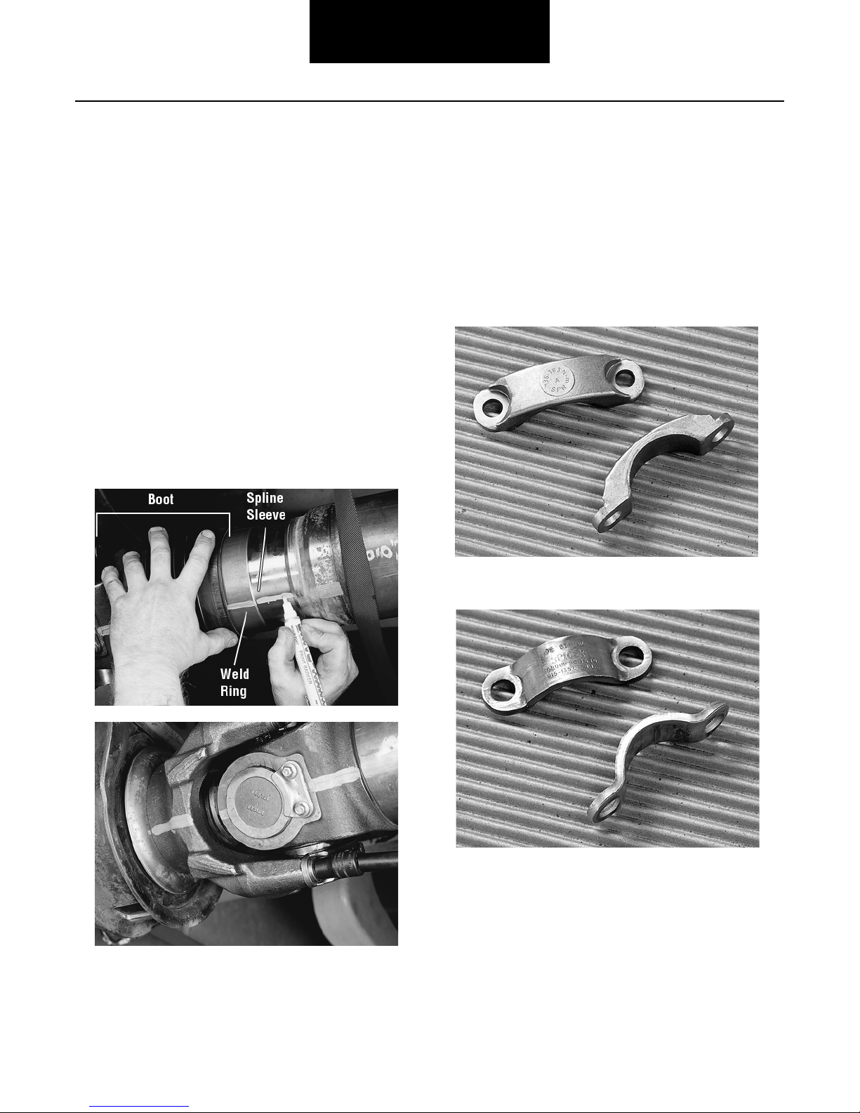
3. Remove the bearing retainers or stamped straps and
bolts at rear end. Discard bolts. Discard stamped
straps.
a. Cold Formed retainers CAN be reused if there is no
damage. If damaged, replace.
b. Stamped straps CANNOT be reused.
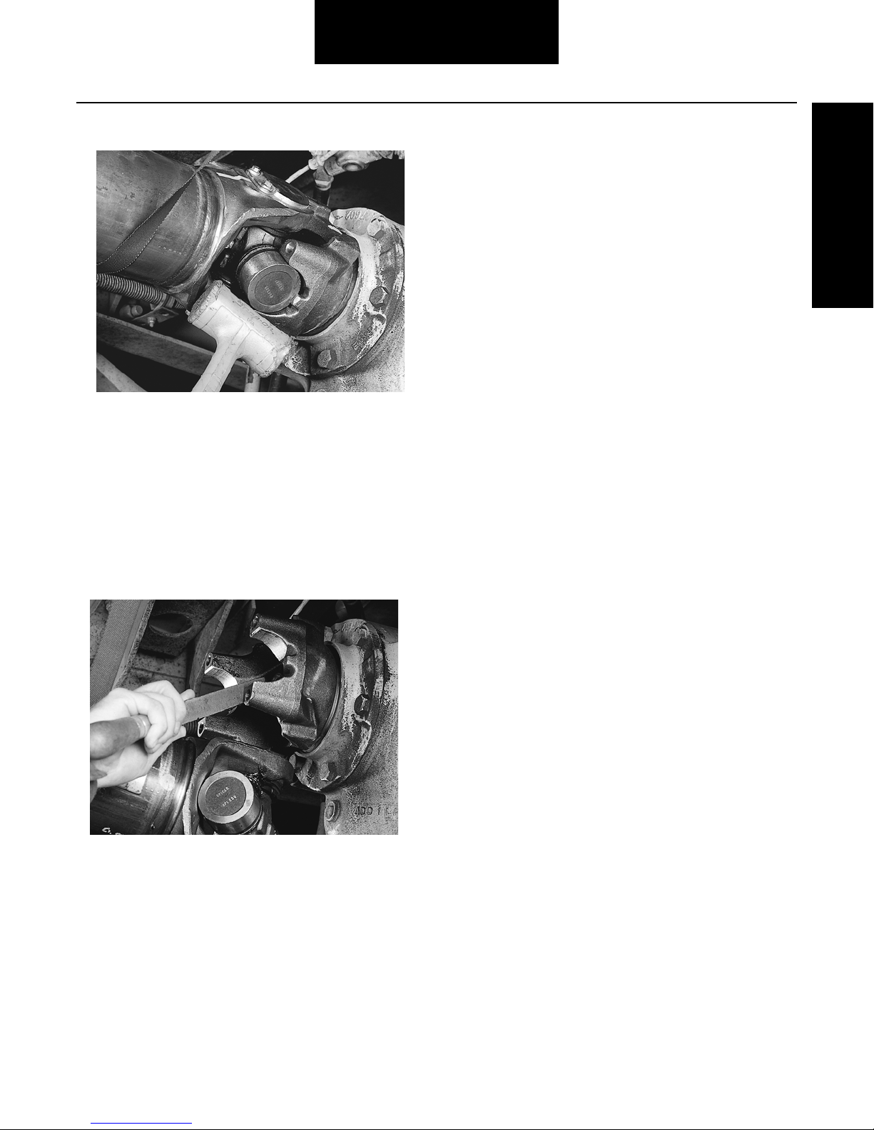
4. It may be necessary to unseat bearing cup assem-
blies by tapping on yoke or bearing cup with a soft-
faced hammer. Once the bearing cup assemblies are
free, collapse the driveshaft until both bearing
assemblies clear the open end yoke cross holes.
Allow the driveshaft to rest on support strap.
Cold Formed Straps
Stamped Straps
16
Driveshaft
Removal
5. Remove bearing retainers or stamped straps and
bolts at the front end.
6. Inspect all end yoke cross hole surfaces and bolt
hole threads for damage. If the bolt hole threads are
damaged, the yoke must be replaced.
7. Inspect for raised metal or fretting on open yoke
cross holes can be removed with a fine-toothed file
and/or emery cloth.
8. Inspect the end yoke cross holes for distortion and
damage.
Inspect Companion Flange/Flange Yokes
1. Inspect all flange bolt hole threads or through holes
for damage. If the bolt hole threads or through holes
are damaged, the flange must be replaced.
Note: For removal procedures for companion flanges, refer to
the original equipment manufacturers’ service and main-
tenance manuals. For removal procedures for flange
yokes, see removel of universal joints in this manual.
2. Inspect all flange faces for galling or damage. If
damaged, the flange must be replaced.
Grease Zerk Removal and Installation
Remove Grease Zerk Fitting or Plug
1. Tilt the universal joint kit or flange yoke and univer-
sal joint kit to allow access to effected grease zerk
fitting or plug. Using pliers or an open-ended
wrench, turn grease zerk fitting or plug counter-
clockwise until it is removed from the journal cross.
Discard the grease zerk fitting or plug.
Grease Zerk Fitting Only
Check for threads in the journal. If threads are
present, proceed to next step. If threads are not
present, replacement of universal joint is necessary.
2. Thoroughly wipe clean the grease zerk fitting or plug
threaded hole.
Install New Grease Zerk Fitting or Plug
3. Install new grease zerk fitting or plug. Tighten to
minimum 15 ft. lbs. (20 Nm). Then continue to turn
only until grease zerk fitting is correctly positioned.
Slip Member Assembly
Remove Grease Zerk Fitting
1. Using pliers or an open-ended wrench, turn grease
zerk fitting counter-clockwise until it is removed
from the slip yoke seal. Discard the grease zerk fit-
ting.
2. Thoroughly wipe clean the grease zerk fitting
threaded hole.
Install New Grease Zerk Fitting
3. Install new grease zerk fitting (Spicer part number
500174-1). Tighten to 31-55 in. lbs. (3.5-6.2 Nm).
Removal Procedure for Universal Joint Kits
Note: Refer to the Appendix for the recommended list of tools
for the following procedure.
Remove Universal Joint Kit(s)

17
Driveshaft
1. For Snap-Ring Style: Using snap-ring pliers,
remove all snap rings. If snap rings are severely cor-
roded or out-of-round, snap rings must be replaced.
1. For Quick Disconnect™ Style: Remove spring tab
bolts and discard, and remove outboard bearing cap
assemblies.
2. Make sure universal joints cross assembly is not
tilted in the yoke. Place bearing cup spacer onto the
base of the arbor press and under the yoke. If the
arbor is larger than the bearing cup diameter, a
smaller diameter push rod will be needed to avoid
damaging the yoke or bearing.
Snap-Ring Style
Quick Disconnect™ Style
Correct Positioning
Incorrect Positioning
Table of contents
Other Spicer Automobile Accessories manuals


