Spicer LM072012 User manual
®
Spicer Drive Axles, Steer Axles,
Driveshafts, and Wheel Ends
Lubrication Manual
May 2015
LM072012

2
General Information
Dana Lubrication Philosophy . . . . . . . . . . . . . . . . 3
Standard Drain Lubricants . . . . . . . . . . . . . . . . 3
Extended Drain Lubricants . . . . . . . . . . . . . . . . . 3
Introduction to Manual . . . . . . . . . . . . . . . . . . 4
Linehaul - 500,000 Mile Extended Lube
Drain Interval . . . . . . . . . . . . . . . . . . . . . . . . . . . . . 4
Vocational - 180,000 Mile Lube
Drain Interval . . . . . . . . . . . . . . . . . . . . . . . . . . . . . 4
WarningsandCautions .. .. .. .. .. .. .. .. .. .. .. . 5
Vehicle Application Definitions. . . . . . . . . . . . . . . 5
City . . . . . . . . . . . . . . . . . . . . . . . . . . . . . . . . . . . . . . 5
Line Haul . . . . . . .. .. .. . . . . . . . .. .. .. . . . . . . . .. .. .. 5
Severe Duty . . . . . . . . . . . . . . . . . . . . . . . 5
Vocational . . . . . . . . . . . . . . . . .. . . . . . . . . . 5
Drive Axle
Drive Axle Lubricants
Heavy-Duty . . . . . . . . . . . . . . . . . . . . . . . 6
Medium-Duty . . . . . . . . . . . . . . . . . . . . . . 6
Drive Axle Lubricant Capacities . . . . . . . . . . . 7
SingleDriveAxleLubricantCapacities ...... 7
TandemDriveAxleLubricantCapacities.. . . 8
Drive Axle Lubrication Procedure . . . . . . . . . . . 9
Inspection . . . . . . . . . . . 9
Drain . . . . . . . . . . . . . . . . . . . . . 9
Fill . . . . . . . . . . . . . . . . . . . . . 9
Steer Axle
Steer Axle Lubricants . . . . . . . . . . . . . . . . 10
Steer Axle Lubrication Procedure . . . . . . 11
Kingpins, Thrust Bearings, and Tie
Rod Ends . . . . . . . . . . . . . . . . . . . . . . 11
On-Highway Applications - Standard . . 11
Wheel Bearings . . . . . . . . . . . . . . . . . . . 11
Oil Bath . . . . . . . . . . . . . . . . . . . . . . . 11
Grease Packed . . . . . . . . . . . . . . . . . . 11
LMS Bearing System . . . . . . . . . . . . . . 11
Steer Axle Grease Procedure . . . . . . 12
Kingpin Joint Greasing Procedure. . . . 12
Tie Rod End Greasing Procedure. . . . 13
Driveline
Driveline Lubrication Intervals . . . . . . . . . . . 14
Driveline Lubrication Procedure . . . . . . . . . . 15
Universal Joint Lubrication Procedure . . 15
SlipSplineLubricationProcedure ........... 16
Wheel End
Wheel End Lubricants . . . . . . . . . . . . . . . 17
Wheel End Lubrication Procedure . . . . . . . . 18
Table of Contents

3
General Information
Dana Lubrication Philosophy
In promoting component reliability and longevity, proper lubrication is the key to a sound and effective maintenance program.
Without effective lubricants at proper levels, remaining maintenance procedures will not keep components functional.
We believe synthetic lubricants have proven to be superior to petroleum products and represent opportunities to promote supe-
rior maintenance and bottom line operating performance while significantly extending component service life and reliability.
Certain products and applications, as noted in this manual, require the use of approved synthetic lubricants.
A list of approved lubricants and suppliers can be found at www.spicerparts.com in the Approved Lubricant Supplier Manual,
DALSM072012.
It is important to perform a daily pre-trip inspection of drivetrain components for lubricant leaks. Leaks should be brought to
the attention of maintenance and immediate corrective action should be taken.
Standard Drain Lubricants
Drive Axle lubricants must meet specific lubricant industry requirements. Refer to the enclosed charts to select the proper
lubricant for your application.
Extended Drain Lubricants (Synthetic Lubricants)
Extended Drain synthetic lubricants offer superior thermal and oxidative stability for extended product performance and
reliability. The superior performance characteristics of these lubricants enable Dana to offer extended drain and extended
warranties. Added benefits include a more efficient drivetrain that translates into proven fuel economy savings over mineral
based lubricants.
Synthetic lubricants are recommended for severe duty applications and in cold climates.
It is important to use the lubricants that meet the current specifications set forth by Dana. Look for the appropriate approval
code on the container.
Drive Axle - Dana Specification: SHAES-256 Rev C
Drive Axle - Dana Specification: SHAES-429
Use of lubricants meeting these specifications will ensure the highest performing lubricants for maximum performance.
Note: Dana discontinued the use of the E500 logo in 2006.
General Information

4
Introduction to Manual
This Lubrication Manual, organized by product, provides easy access to the following lube information:
• Type of lubricant
• Change intervals
• Capacities
• General lubrication procedures
• Warnings and Cautions
Note: Refer to the Approved Lubricant Supplier Manual, DALSM072012, to verify approved lubrication trade name and product.
Linehaul - 500,000 Mile Extended Lube Drain Interval
The extended drain interval program applies to the Dana axles listed below that meet the following conditions:
• Heavy-Duty and Medium-Duty axles
• Line haul service (On-highway)
• Lubricant approval levels
• Drive Axle – SHAES-256 Rev C
• Factory filled with lubricants approved for 500,000 mile drain cycles (US/Canada); 250,000/400,000Km (Outside US/
Canada
• Refer to charts listed in this manual for axle drain intervals when using “Extended Drain Lubricants”
• A Dana-approved lubricant must be used to keep the extended warranty in place. The extended drain program
and any extended warranty program are separate programs.
Note: For specific detail on Dana extended warranty programs refer to the Dana Warranty Guide or call 1-877-777-5360.
Note: For a complete list of Dana “approved lubricants” for extended drain, refer to Approved Lubricant Suppliers Manual,
DALSM072012
Vocational - 180,000 Mile Lube Drain Interval
This will outline the performance requirements of lubricants intended for use in vocational Spicer® drive
axles that are allowed the 180,000 mile or three year extended drain interval. The approved lubricants may
be factory installed at the truck manufacturer, or service filled up to 500 miles, and may remain in the drive
axles for the 180,000 mile or three year drain interval, whichever comes first.
Lubricant approval levels
• Axle – SHAES-429
General Information

5
General Information
Warnings and Cautions
Before working on a vehicle, place transmission in neutral, set brakes, and block wheels.
When switching between types of lubricants, all areas of each affected component must be thouroughly drained.
Do not introduce additives and friction modifiers.
Do not mix lubricants of different grades.
Do not mix mineral and synthetic lubricants.
Do not mix heavy-duty, multi-purpose lithium based (#2 grade) grease with sodium- based grease.
Vehicle Application Definitions
City
• Pickup and delivery service within cities and/or suburban areas.
• 100% of operation on road surfaces of concrete, asphalt, and maintained gravel.
• Three (3) miles between starts/stops (typical).
• 100% load going / up to 40% load return (typical).
Line Haul (On-highway)
• High mileage operation (over 60,000 miles [96,500 Km] per year).
• On-highway or good to excellent concrete or asphalt.
• More than 30 miles [48 Km] between starting and stopping.
• 4x2, 6x2, 6x4 tractor/trailer combinations and straight trucks.
• Check fluid levels and inspect for leaks at regular PM maintenance intervals, not to exceed 12,000 miles.
Severe Duty
• Consistent operation at or near maximum GCW or GVW ratings.
• Dirty or wet environments.
• Consistent operation on grades greater than 8%.
Vocational
• Low mileage operation (under 60,000 miles [96,500 Km] per year).
• Off-highway or areas of unstable or loose unimproved road surfaces.
• Less than 30 miles [48 Km] between starting and stopping.
• Heavy-duty, off-road, or specialized application type vehicles.
• Check fluid levels and inspect for leaks every 50 hours.

6
Drive Axle
Drive Axle Lubricants
Dana Recommends the Use of Dana-Approved Lubricants for Extended Drain
Use the chart to locate the correct lubricant and change interval.
Heavy-Duty
Synthetic or
Mineral
Lubricant
Specification
SAE
Viscosity Grade
Change Interval for
Line Haul*
Change Interval for
Vocational*
Synthetic SHAES-256 Rev C SAE 75W-90 500,000 miles [800,000 Km]
or 5 years
N/A
Synthetic SHAES-429 SAE 75W-90
SAE 80W-140
N/A 180,000 miles [288,000 Km]
or 3 years
Mineral SAE J2360 75W, 75W-90,
75W-140,
80W-
90, 85W-140
120,000 miles [193,000 Km]
or 1 years
60,000 miles [96,500 Km]
or 1 year
Medium-Duty
Synthetic or
Mineral
Lubricant
Specification
SAE
Viscosity Grade
Change Interval for
Line Haul*
Change Interval for
Vocational*
Synthetic SHAES-256 Rev C SAE 75W-90 250,000 miles [400,000 Km]
or 5 years
N/A
Synthetic SHAES-429 SAE 75W-90
SAE 80W-140
N/A 180,000 miles [288,000 Km]
or 3 years
Mineral SAE J2360 75W, 75W-90,
75W-140, 80W-
90, 85W-140
100,000 miles [160,000 Km]
or 1 years
60,000 miles [96,500 Km]
or 1 year
Note: Extended warranties require the use of synthetic lubricant approved to SHAES-256 Rev C.
*For line haul and vocational definitions, see page 5.

7
Drive Axle
Drive Axle Lubricant Capacities
Single Drive Axle Lubricant Capacities
Capacities are sorted by model number. The suffixes are
included when necessary.
Single Axle Model Number Pints Liters
S110 14 6.6
S130 13.6 6.4
S135 24 11.4
S140 19 8.9
S150 24 11.4
S21-170 37 17.5
S21-170D 37 17.5
S23-170 37 17.5
S23-170D 37 17.5
S25-170 37 17.5
S25-170D 37 17.5
S23-190 37 17.5
S23-190D 37 17.5
S26-190 37 17.5
S26-190D 37 17.5
S30-190 40 18.9
S30-190D 40 18.9
S260 (SB) 54 25
15040 (P, T) 24 11.4
15040 (S) 21 9.9
17060 (A, D, S) 28 13
19050 (P, T) 33 15.6
19050 (S) 25 11.8
19055 (D, S) 34 16.1
19055 (P, T) 35 16.6
19060 (A, D, S) 28 13.2
19060 (P, T) 35 16.6
21060 (A, D, S) 28 13.2
21060 (P, T) 35 16.6
21065 (D, S) 34 16.1
Single Axle Model Number Pints Liters
21065 (P, T) 35 16.6
21070 (D, S) 40 18.9
21080 (A, D, S) 40 18.9
22060 (A, D, S) 28 13.2
22060 (P, T) 35 16.6
22065 (D, S) 34 16.1
22065 (P, T) 35 16.6
22080 (A, D, S) 40 18.9
23070 (D, S) 40 18.9
23070 (P, T) 39 18.5
23080 (A, D, S) 40 18.9
23080 (P, T) 41 19.4
23085 (C, D, S) 40 18.9
23085 (P, T) 41 19.4
23105 (A, D, S) 48 22.7
26080 (A, D, S) 40 18.9
26080 (P, T) 41 19.4
26085 (P, T) 41 19.4
26105 (A, D, S) 48 22.7
30055 (P) 36 17
30105 (A, D, S) 46 21.5
35055 (P) 36 17

8
Drive Axle
Tandem Drive Axle Lubricant Capacities
Capacities are sorted by model number. The prefixes are
included when necessary.
Tandem Axle Model Number Pints Liters
D40-155 27 12.8
R40-155 23 11.0
D40-156 27 12.8
R40-156 20 9.5
D40-170 39 18.5
R40-170 37 17.5
D46-170 39 18.5
R46-170 37 17.5
D50-170 39 18.5
R50-170 37 17.5
D52-190 42 19.9
R52-190 40 18.9
D60-190 42 19.9
R60-190 40 18.9
D52-590 42 19.9
R52-590 40 18.9
40 DDS(P), DSS(P) 40 18.9
40 DDH(P), DSH(P) 31 14.7
40RDS, RSS 37 17.5
40RDH, RSH 28 13.2
44 DSH(P) 31 14.7
44 RDH, RSH 28 13.2
341 DC, DP, DT(P), DS(P) 39 18.5
341 RC, RP, RS, RT 36 17
344 DA(P), DD(P), DS(P) 31 14.7
344 RS 28 13.2
402 DP, DT(P), RP, RT 34 16.1
402 DS(P) 39 18.5
402 RS 36 17
404 DA(P), DD(P), DS(P) 31 14.7
404 RA, RD, RS 28 13.2
405 DA(P), DD(P), DS(P) 31 14.7
Tandem Axle Model Number Pints Liters
405 RA, RD, RS 28 13.2
451 DP(P), DT(P), RP, RT 34 16.1
451 DC(P), DS(P) 39 18.5
451 RC, RS 36 17
454 DA(P), DD(P), DS(P) 31 14.7
454 RA, RD, RS 28 13.2
461 DD(P), DS(P) 43 20.3
461 DP(P), DT(P) 46 22
461 RC, RP, RT 39 18
461 RD, RS 40 18.9
462 DD(P), DS(P) 40 18.9
462 RD, RS 37 17.5
463 DD(P), DP(P), DS(P), DT(P) 40 18.9
463 RD, RP, RS 37 17.5
521 DD(P), DP(P), DS(P), DT(P) 42 19.9
521 RC, RD, RP, RS, RT 39 18.5
581 DD(P), DP(P), DS(P) 42 19.9
581 RD, RP, RS 39 18.5
601 DC(P), DD(P), DP(P) 42 20
601 RP 39 18.5
651 DP(P) 41 19.4
651 RP 37 18
652 DP(P) 41 19
652 RP 37 18

9
Drive Axle Lubrication Procedure
Inspection
Drive axles should be checked for weeps and/or leaks during
the operator’s daily walk around inspection of the vehicle.
Drive axle lubrication levels should be checked every 25,000
miles (40,000 km) or during routine engine oil changes.
Drain
1. Drain when the lube is at normal operating termpera-
ture (150-200°F). It will run freely and minimize the time nec-
essary to fully drain the axle, this ensures the axle is flushed.
2. Depending on the axle model, remove the drain plug
from the bottom of the drive axle housing or remove one of
the bottom carrier-to-housing fasteners and allow the lube to
drain into a suitable container.
NOTE: Dispose of all used lubricants properly by following
disposal methods approved for mineral and synthetic-based
oils.
3. After the initial oil change, inspect the drain plug
for large amounts of metal particles.These may be signs
of damage or extreme wear in the axle. Clean and install
the drain plug after the axle has completely drained.
Fill
1. With the vehicle on level ground, remove the fill plug
from the drive axle rear cover or the side of the carrier assem-
bly, depending on the axle model.
2. Fill the housing with lube until the level is even with
the bottom of the fill hole as shown below.
3. If the wheel ends are removed, refer to the “Wheel
End Lubrication Procedure” in this manual.
NOTE: Lube fill capacities (see chart on previous pages) are
basic guidelines and will vary based on the angle the axle is
installed.
TIP: The axle can be filled through the axle housing breather
hole. Fill until the lube level is even with the bottom of the fill
hole.
Drive Axle
Correct lube level at bottom of ller hole.

10
Steer Axle
Steer Axle Lubricants
The standard lubricants specified by the Steer Axle Product
Engineering group are as follows
Note: For line haul and vocational definitions, see page 5.
Type of Lubricant
System
Lubricant SAE Change Interval for
Line Haul
Chnage Interval for
Vocational
Wheel End Mineral Oil SAE 75W-
90
100,000 miles
[161,000 km] or 1 year
30,000 miles [48,000
km] or 6 months
Wheel End Mineral Grease-NLGI #2 #2 grade
100,000 miles
[161,000 km] or 1 year
30,000 miles [48,000
km] or 6 months
LMS-Low Lube1Synthetic Oil
SAE 50
PS-164 Rev
7
250,000 miles
[400,000 km] or 1 year
250,000 miles
[400,000 km] or 1 year
LMS-Low Free1Synthetic Oil
SAE 50
PS-164 Rev
7
None (only needed if
tear down)
None (only needed if
tear down)
LMS-Low Lube1Semi-Fluid Synthetic
Grease
Chevron Delo
SF
50,000 miles [800,000
km] or 3 years
50,000 miles [800,000
km] or 3 years
LMS-Low Lube1Semi-Fluid Synthetic
Grease
Mobilith SHC
007
50,000 miles [800,000
km] or 3 years
50,000 miles [800,000
km] or 3 years
King Pin Joint Grease /
Tie Rod Ends
Heavy-Duty, multipur-
pose
lithium based
#1 grade or
#2 grade
25,000 miles [40,000
Km] or 6 months
Every 50 hours
1 For easy identification, note that the Dana LMS-Low Lube
brake uses a special “button head” grease fitting and the
Dana LMS-Lube Free brake does not have a grease fitting.

11
Steer Axle
Steer Axle Lubrication Procedure
Lubrication
Proper lubrication practices are important in maximizing the
service life of your steer axle assembly.
Kingpins, Thrust Bearings, and Tie Rod Ends
On-Highway Applications - Standard
Pressure lubricate every 6 months or 25,000 miles (40,000
km).
A more frequent lubrication cycle is required for axles used
in on/off highway, refuse, or other severe service applica-
tions.
Use heavy-duty, multipurpose lithium base (#2 grade)
grease.
Do not mix with sodium base grease.
Note:
If it is difficult to grease either the upper or lower bush-
ing, try greasing the bushings with the vehicle jacked
up and supported on axle stands to improve grease
flow and help flush out contamination.
Wheel Bearings
Lubricate wheel bearings with an approved drive axle lubri-
cant (oil bath) or heavy duty grease (grease packed) depend-
ing on the type of axle lube system. Identify the type of
lubrication system on your vehicle before servicing wheel
bearings. Improper lubrication can result in reduced seal life
and potential damage to bearings and spindles.
Oil Bath
Lubricate wheel end assembly with a drive axle lubricant that
meets MIL-L-2105D specifications. Either 80W-90 mineral
based or 75W-90 synthetic lube is acceptable. Check lubri-
cant level at each greasing interval. Maintain lube level to
center-line of axle or fill line on hub cap. Always check lube
level on flat ground.
Do not mix lubricants of different grades. Do not mix min-
eral and synthetic lubes. Different brands of same grade
may be mixed. Do not pack bearings with grease when
using an oil bath system. This practice can restrict the flow
of lubricant to the wheel seal.
Grease Packed
Thoroughly clean bearings, spindle, hub cap, and hub cavity.
Parts may be washed in a suitable commercial solvent. Be
certain parts are free of moisture or other contaminants.
Refer to vehicle and/or wheel seal manufacturer’s recom-
mendations when using grease. Fill wheel hub with grease to
inside diameter of bearing cups. Fill hub cap. Grease bearing
cones by forcing grease between rollers, cones, and cage.
CAUTION
Never mix oil bath and grease packed wheel ends.
LMS Bearing System
Refer to Dana Spicer information Bulletin ABIB-9606.
CAUTION

12
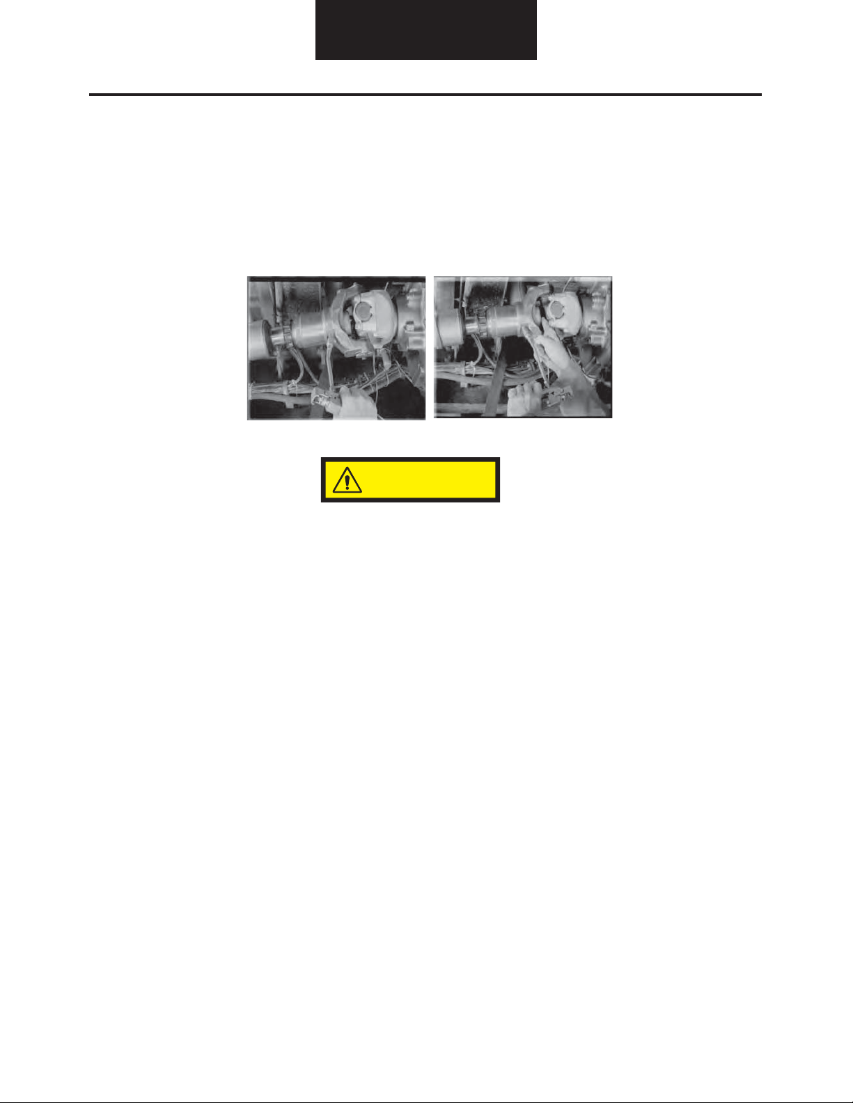
Steer Axle Grease Procedure
Kingpin Joint Greasing Procedure
1. With the vehicle on a level surface, block the front and
the back of at least one of the drive axle wheels to keep
the vehicle from moving. Set the parking brake.
NOTE: Do NOT raise the vehicle off the ground during
greasing. If the wheels are off the ground, grease will not
pass through the thrust bearing properly. This may cause
premature bearing wear and/or failure.
2. Clean all grease fittings before applying new grease.
3. Start by greasing the top bushing grease fitting. Grease
must be applied until new (clean) grease comes from
between the shim pack and the steer knuckle and/or
beam.
Top Bushing Grease Fitting
Grease Fitting
Contaminated Grease – Continue Greasing
NOTE: The greasing of steer axle components is not just to
lubricate the internal components. More importantly, it is to
flush contamination that may have worked its way past the
seals. Greasing MUST continue until clean grease is purged.
4. Now apply grease to the bottom bushing fitting. Keep
greasing until you see clean grease being purged and the
thrust bearing is full of grease.
Bottom Bushing Grease Fitting
Grease Fitting
NOTE: Rotating the knuckle assembly during the greasing
process may help to complete the purge. Do NOT raise the
vehicle during this process.
Grease Until Clean Grease is Purged
Steer Axle
13
Steer Axle Grease Procedure
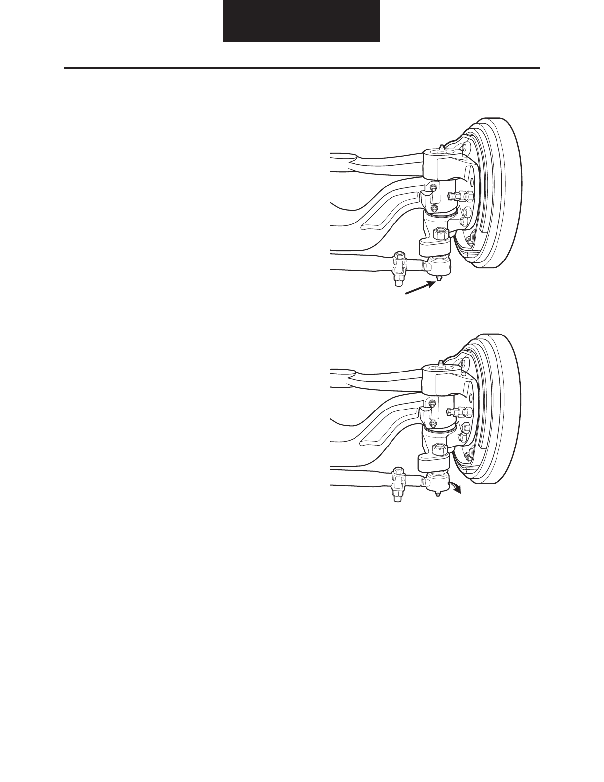
Tie Rod End Greasing Procedure
1. With the vehicle on a level surface, block the front and
the back of at least one of the drive axle wheels to keep
the vehicle from moving. Set the parking brake.
NOTE: Always measure the tie rod end radial and/or end-
play before greasing. Greasing prior to taking measure-
ments will give a false reading.
NOTE: The greasing of steer axle components is not just to
lubricate internal componets. More importantly it is to flush
contamination that may have worked its way past the seals.
Greasing MUST continue until clean grease is purged from
the purge valve.
2. Clean all grease fittings before applying new grease.
3. Apply grease to fitting. Grease must be applied until new
(clean) grease comes from the purge valve on the end of the
tie rod.
Always measure end-play before re-greasing
Grease Fitting
Purge Valve
Steer Axle

14
Driveline
Driveline Lubrication Intervals
For assistance identifying the driveshaft model, see DSMT0100.
Spicer® Driveshaft Lubrication Intervals
Product City On Highway Line Haul On/Off Highway
10-Series
(1480 thru 1810 & SPL90)
Note: Slip member also requires
lubrication.
5,000/8,000 miles
[8,000/12,000 Km]
or 3 months (which
ever comes first)
10,000/15,000 miles
[16,000/24,800 Km]
or 3 months (which
ever comes first)
10,000/15,000 miles
[16,000/24,800 Km]
or 3 months (which
ever comes first)
5,000/8,000 miles
[8,000/12,000 Km]
or 3 months (which
ever comes first)
Spicer Life Series® Medium Duty
(SPL55, 70, & 100)
Booted and permanently lubrcated
slip member.
25,000 miles
[40,000 Km]
or 6 months (which
ever comes first)
25,000 miles
[40,000 Km]
or 6 months (which
ever comes first)
25,000 miles
[40,000 Km]
or 6 months (which
ever comes first)
25,000 miles
[40,000 Km]
or 6 months (which
ever comes first)
Spicer Life Series Heavy Duty
(SPL140)
Standard Spicer Life Series
U-Joint. Booted and permnently
lubricated slip member.
25,000 miles
[40,000 Km]
or 6 months (which
ever comes first)
100,000 miles
[160,000 Km]
or 6 months (which
ever comes first)
100,000 miles
[160,000 Km]
or 6 months (which
ever comes first)
25,000 miles
[40,000 Km]
or 6 months (which
ever comes first)
Spicer Life XL™ First Lubrication Cycle*
Product City On Highway Line Haul On/Off Highway
Spicer Life XL
(SPL170XL, 250XL, & 350XL)
Extended lubrication U-Joint.
Booted and permanently lubrcated
slip member.
100,000 miles
[160,000 Km]
or 1 year (which
ever comes first)
350,000 miles
[560,000 Km]
or 3 years (which
ever comes first)
350,000 miles
[560,000 Km]
or 3 years (which
ever comes first)
100,000 miles
[160,000 Km]
or 1 year (which
ever comes first)
Spicer Life XL™ Re-Lubrication Cycle*
Product City On Highway Line Haul On/Off Highway
Spicer Life XL
(SPL170XL, 250XL, & 350XL)
Extended lubrication U-Joint.
Booted and permanently lubrcated
slip member.
25,000 miles
[40,000 Km]
or 6 months (which
ever comes first)
100,000 miles
[160,000 Km]
or 6 months (which
ever comes first)
100,000 miles
[160,000 Km]
or 6 months (which
ever comes first)
25,000 miles
[40,000 Km]
or 6 months (which
ever comes first)
Spicer Life SF™ Lubrication Cycle
Product City On Highway Line Haul On/Off Highway
Spicer Life SF
(SPL170SF & 250SF)
Service Free
Permanently lubricated for life of product
* Spicer Driveshaft Division recommends re-lubrication with grease meeting NLGI Grade 2 specifications with an operating range
of +325°F/+163°C to -10°F/-23°C.

15
Driveline
Driveline Lubrication Procedure
Inadequate lubrication can cause driveline failure which can result in separation of the driveline from the vehicle.
A separated driveline can result in serious injury or death. In order to avoid driveline failure, including driveline separation,
you must follow the instructions below.
We require lubrication with Chevron Ultra-Duty EP-2 or a compatible lithium-based grease meeting N.L.G.I. Grade 2 specifica-
tions as well as ASTM D4950 “LB” specifications.
Among the most common causes of universal joint and slip spline failure is lack of proper lubrication. Properly sized Spicer uni-
versal joints that are adequately re-lubricated at recommended intervals will normally meet or exceed fleet operational require-
ments. Inadequate re-lube cycles and failure to lubricate the joints and slip spline properly not only cause joint failures, but lead
to other problems such as slip spline seizures. Proper re-lubrication flushes the universal joints, thus removing abrasive contam
-
inants from the universal joint bearings.
1. Carefully review the lubrication specifications in the manual.
2. Re-lubricate at recommended intervals.
3. Only use approved lubricants.
Spicer replacement universal joint kits contain only enough grease to provide needle bearing protection during storage. It is,
therefore, necessary to completely lubricate each replacement kit prior to assembly into the driveshaft yokes. Each journal cross
lube reservoir should be fully packed with a grease listed on the previous page. Each bearing assembly should also be wiped with
the same grease, filling all the cavities between the rollers and applying a liberal grease coating to the bottom of each race. After
the kits are installed into the driveshaft yokes and, prior to placing into service, they should be re-lubed, through the zerks, using
the same grease.
NOTE:
We recommend all driveshafts be inspected for wear and damage every time the vehicle is serviced. This includes any
scheduled and/or unscheduled maintenance that occurs within the driveshaft lube intervals.
Universal Joint Lubrication Procedure
1. Use the proper lubricant to purge all four bearing seals of each universal joint. This flushes abrasive contaminants from
each bearing and assures all four bearings are filled properly. Pop the seals. Spicer seals are made to be popped.
2. If any of the seals fail to purge, move the driveshaft from side-to-side while applying gun pressure. This allows greater
clearance on the thrust end of the bearing that is not purging. (On two-headed zerk fittings, try greasing from the oppo-
site lube fitting.)
3. Because of the superior sealing capability of the Spicer Seal design on the 1610, 1710, 1760, 1810, and 1880 Series,
there will occasionally be one or more bearing seals of a universal joint that may not purge. Seal tension then has to be
released. Bearing seals must purge to ensure adequate lubrication at all four universal joint bearings.
To Release Seal Tension:
4. On Quick Disconnect™ half round end yokes, remove the universal joint kit from the yoke and apply grease. Re-install
the universal joint kit, with new bolts, in the yoke and torque to specifications as listed in DSSM-3264.
5. On full round closed hole yokes, loosen the bolts holding the bearing assembly that does not purge to release seal ten-
sion. It may be necessary to loosen the bearing assembly approximately 1/16” minimum. If loosening does not cause
purging, remove the bearing assembly to determine cause of blockage.
6. Remove bolts and replace.
NOTE: The self-locking bolt design for full round yokes uses serrated bolts with lock patch and does not require a lock strap. DO
NOT reuse any retaining bolt. If loosening or removal of a bolt is necessary, replace it with a new one.
CAUTION
16
Driveline
Slip Spline Lubrication Procedure
Always use a good E.P. grease meeting NLGI Grade 2 specifications on Glidecote™ and steel splines. The same lubricant used for
universal joints is satisfactory for slip splines.
Re-lube splines as the interval prescribed in the “Driveline Lubricants” section. Apply grease gun pressure to lubrication zerk
until lubricant appears at pressure relief hole in welch plug
at slip yoke end of spline (Photo 1). At this point, cover pressure
relief hole with finger and continue to apply pressure until grease appears at slip yoke seal (Photo 2). This will insure complete
lubrication of spline.
Figure 1 Figure 2
In cold winter months, activate the slip spline assembly by driving the vehicle sufficiently to cause displacement of the
grease prior to its stiffening. Otherwise, the slip yoke plug may be forced out due to hydraulic pressure causing loss of
grease and allowing abrasive contaminants to enter the slip spline
.
CAUTION

17
Wheel End
Wheel End Lubricants
Use the chart to locate the correct lubricant and change interval.
Note: For line haul and vocational definitions, see page 5.
Product Lubricant Type SAE Change Interval for
Line Haul
Change Interval for
Vocational
Drive Axle
LMS
Synthetic1
SHAES 256 Rev C
SHAES 429
SAE 75W-90, 80W-140 500,000 miles
[800,000 km]
or 5 years
180,000 miles
[288,000 km]
or 3 years
Drive Axle
(Adjustable)2
Synthetic
SHAES 256 Rev C
SHAES 429
SAE 75W-90, 80W-140 250,000 miles
[400,000 km]
or 3 years
180,000 miles
[288,000 km]
or 3 years
Drive Axle
(Adjustable)2
Mineral Base
SAE J2360
SAE 75W-90, 75W-140,
80W-90, 85W-140
120,000 miles
[193,000 km]
or 1 year
60,000 miles
[96,500 km]
or 1 year
Steer Axle
Oil Bath LMS
Synthetic1
SHAES 256 Rev C
SAE 75W-90 500,000 miles
[800,000 km]
or 5 years
120,000 miles
[193,000 km]
or 2 years
Steer Axle
Oil Bath (Adjusted)
Synthetic
SHAES 256 Rev C
SHAES 429
SAE 75W-140, 75W-90 120,000 miles
[193,000 km]
or 1 year
60,000 miles
[96,500 km]
or 6 months
Steer Axle
Oil Bath (Adjusted)
Mineral Base
SAE J2360
75W, 75W-90, 80W-90,
85W-140
120,000 miles
[193,000 km]
or 1 year
60,000 miles
[96,500 km]
or 6 months
Steer Axle
Semi-fluid
(Adjusted)
Semi-fluid Synthetic
Grease
Delo SF, Mobil SHC 0073 120,000 miles
[193,000 km]
or 1 year
60,000 miles
[96,500 km]
or 6 months
Steer Axle
Grease Pack
(Adjusted)
Heavy-Duty Multipurpose
Lithium Based3
#2 Grade 120,000 miles
[193,000 km]
or 1 year
60,000 miles
[96,500 km]
or 6 months
1Only approved lubricant for LMS wheel ends
2Refer to maintenance manual for inspection and adjustment intervals
3Do not mix with sodium base grease
18
Wheel End
Wheel End Lubrication Procedure
Before operating the axle, the wheel hub cavities and
bearings must be lubricated to prevent failure.
When wheel ends are serviced, follow Dana’s wheel end
lubrication procedure before operating the axle.
Spicer axles may be equipped with either of two wheel end
designs:
• Wheel ends with an oil fill hole
• Wheel ends without an oil fill hole
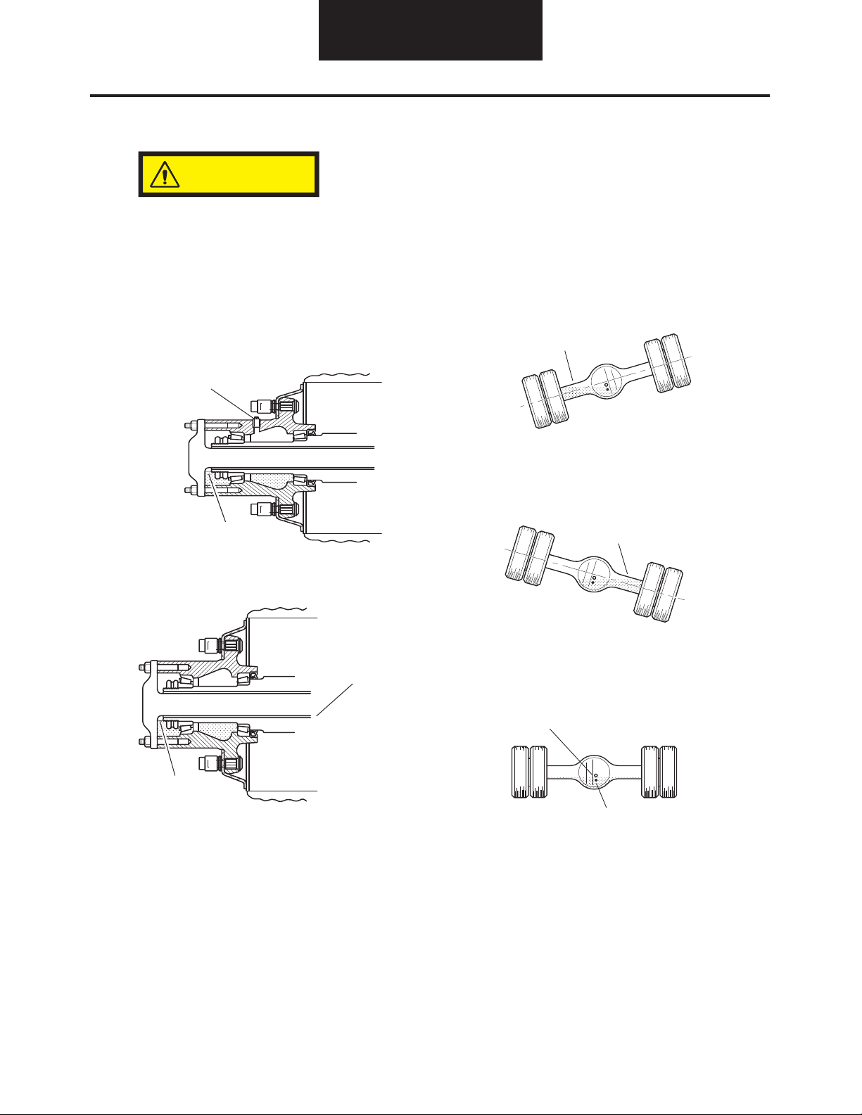
Wheel End Lubrication Procedure
(with oil fill hole)
1. Rotate the wheel end hub until the oil fill hole is up.
2. Remove the oil fill plug.
3. Pour 0.5 pint [0.2 liter] of axle sump lubricant into
each hub through the wheel end fill hole.
4. Install oil fill plug and tighten to specified torque.
Wheel End Lubrication Procedure (without oil fill
hole)
1. With axle level and wheel ends assembled, add
lubricant through filler hole in axle housing cover
until fluid is level with the bottom of filler hole.
2. Raise the left side of the axle 6 in. [152 mm] or
more. Hold axle in this position for one minute.
3. Raise the right side of the axle 6 in. [152 mm] or
more. Hold axle in this position for one minute.
4.
With axle on a level surface, add lubricant through
housing cover oil filler hole until fluid is level with
the bottom of the hole.
NOTE: Axles without wheel end fill holes require additional
lubricant to
bring the lubricant level even with the
bottom of the fill
hole.
Wheel end oil ll hole
Proper lubricant level
Lubricant ow from sump
Proper lubricant level
Oil will run into Wheel End
Oil will run into Wheel End
Fill Housing with oil to bottom of Plug
Temperature Sensor Mounting Hole
CAUTION

Printed in USA LM072012
For spec’ing or service assistance, call 1-877-777-5360 or visit our website at www.dana.com
Dana Commercial Vehicle Products Group
3939 Technology Drive
Maumee, Ohio, USA 43537
www.dana.com
All applications must be approved by the Application Engineering Department. Specifications and/or design are subject to change without notice or obligation.
Table of contents
Other Spicer Automobile Accessories manuals


