Meritor Wabco 1000 Series Guide
TP-92116
Revised 8-98
TP-92116
16579/Meritor Revised 8-98
Printed in the USA © Copyright Meritor WABCO, 1998
Page 1
SERVICE PARTS
INSTRUCTIONS
Installing the
Meritor WABCO
System Saver 1000 and
1200 Series Air Dryers
For Use on Tractors, Trucks
and Buses with Air Brakes
Installation Requirements
1
2
3
4
5
M
E
R
I
T
O
R
W
A
C
O
P
/
N
4
3
4
1
0
0
3
1
0
0
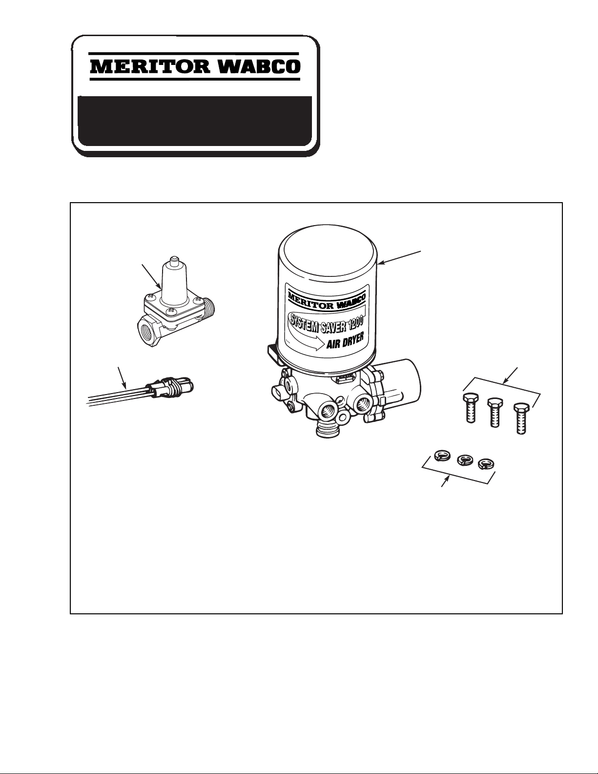
Item Qty. Description
1 1 12- or 24-Volt Air Dryer
2 3 Capscrew (1/2"-13 UNC – 2A x 1.375)
3 3 Lock Washer (1/8" thick)
4 1 Heater Power Harness
5 1 Pressure-Controlled Check Valve

TP-92116
Revised 8-98 16579/Meritor
Page 2
© Copyright Meritor WABCO, 1998 Printed in the USA
Service Notes
You must follow your company safety procedures when you install the System Saver 1000 and 1200 Series
air dryers. Meritor WABCO uses the following types of notes to give warning of possible safety problems
and to give information that will prevent damage to the air dryer.
WARNING
A warning indicates procedures that must be followed exactly. Serious personal injury can occur if the
procedure is not followed.
CAUTION
A caution indicates procedures that must be followed exactly. If the procedure is not followed, damage to
equipment or components can occur. Serious personal injury can also occur in addition to damaged or
malfunctioning equipment or components.
This symbol is used to indicate fasteners that must be tightened to a specific torque value.
NOTE
A note indicates an operation, procedure or instruction that is important for correct installation. A note
can also give information that will make installation quicker and easier.
Meritor WABCO System Saver Single Cartridge Air Dryer
Publications
MM34 Maintenance Manual
PB-96134 Parts Book
TP-9672 Air Dryer Application Guidelines
TP-9772 26” x 40” Troubleshooting Guide
Wall Chart
TP-97101 Troubleshooting Guide
(laminated card)
T-97105V Troubleshooting and Repair Video
(30 min.)
To order literature contact the Meritor Customer
Support Center at 800-535-5560.
Part Number Selection Guide (See page 3 for application information)
Series Voltage (100 Watts) Replacement Kit ID Tag Number
1200 Standard Application 12 volts R955205 432 413 001 0
1200 Standard Application 24 volts R955206 432 413 002 0
1200E Use with Holset E
Compressor 12 volts R955207 432 413 006 0
1200E Use with Holset E
Compressor 24 volts R955208 432 413 009 0
1200U Discharge Line
(Continuous Flow) Installation 12 volts R955210 432 413 007 0
1200U Discharge Line
(Continuous Flow) Unloader
Installation
24 volts R955211 432 413 021 0

TP-92116
16579/Meritor Revised 8-98
Printed in the USA © Copyright Meritor WABCO, 1998
Page 3
Introduction
This installation manual contains basic installation
instructions for standard air systems and
includes special instructions for installing the
Pressure-Controlled Check Valve (PCCV). It also
includes System Saver 1000 and 1200 air dryer
diagnostics. Read all instructions before
proceeding with your installation.
Application Information:
Cubic Feet per Minute (CFM) Less than 25 CFM
Normal Duty Cycle Less than 30%
Typical Compressor 2 Minutes or Less
Loaded Time
WARNINGS
To prevent serious eye injury, always wear
safe eye protection when you perform vehicle
maintenance or service.
Do not work around or under the vehicle
unless it is parked on a level surface. Use blocks to
keep the vehicle from moving. A moving vehicle
can cause serious personal injury and damage.
Remove all air from the air system before
servicing any component in the air system.
Pressurized air can cause serious personal injury.
Basic Installation Instructions
TYPICAL INSTALLATION FOR SYSTEM SAVER 1000 AND 1200 SERIES AIR DRYER
GOVERNOR COMPRESSOR
INTAKE LINE
UNLOADER
PORT
GOVERNOR
PORT
COMPRESSOR
DRYER INLET
COMPRESSOR
DISCHARGE
LINE PURGE VALVE
DRYER OUTLET
CHECK
VALVE SYSTEM
RESERVOIR
SYSTEM
RESERVOIR SYSTEM
RESERVOIR
SYSTEM
RESERVOIR
SUPPLY
(WET) TANK
PRESSURE-CONTROLLED
CHECK VALVE
TO BRAKE SYSTEM

TP-92116
Revised 8-98 16579/Meritor
Page 4
© Copyright Meritor WABCO, 1998 Printed in the USA
Mounting the Air Dryer
1. Park the vehicle on a level surface, stop the
engine, set the parking brake and block
the wheels.
2. Drain pressurized air from
all reservoirs
to
0 psi (0 bar). Open
all
draincocks to expel
collected water.
3. Inspect the vehicle for a suitable mounting
location that meets the following criteria. The
air dryer will operate most efficiently when you
follow these guidelines.
a. Mount the air dryer where cool air can flow
around it . . . but not directly in the vehicle
wind stream . . . and at least 12 inches away
from any heat source.
b. Mount the air dryer
LOWER
than the
compressor so that water in the delivery line
flows into the air dryer. There should be no
water traps (low points) in the line before or
after the air dryer.
c. Mount the air dryer in a vertical position or
within 30˚ of vertical, with the desiccant
cartridge at the top.
d. Allow at least two inches (51 mm) of
clearance above the top of the air dryer for
servicing the desiccant cartridge.
e. Mount the air dryer in a location where it is
not subject to direct splash or spray from
a wheel.
4. Apply the adhesive-backed template to the
selected location.
Figure 1
.
Figure 1
2.875" / 73 mm
2.063" / 52 mm
4.125" / 105 mm
Air Dryer Installation Template

TP-92116
16579/Meritor Revised 8-98
Printed in the USA © Copyright Meritor WABCO, 1998
Page 5
NOTE
Check the vehicle manufacturer’s specifications
before drilling into the frame member.
5. Drill 9/16-inch holes at each cross mark. Use a
mounting bracket, if necessary.
Figure 2 or 3
.
6. Mount the air dryer using the capscrews and
lock washers provided.
7. Tighten each capscrew to 22-30 lb-ft
(30-40 N
O
m).
Connecting the Air Lines
NOTE
Use pipe sealant or teflon tape on all air fittings.
NOTE
The reference to nylon tubing throughout this
manual refers to SAE J844 air brake nylon tubing.
1. Connect the delivery line from the compressor
to the air dryer inlet port (1/2" NPTF, marked
“1”) with 1/2-inch-ID minimum stainless-steel
braided teflon hose. The air dryer will operate
most efficiently when the following guidelines
are used.
a. The delivery line should follow a
DOWNHILL
route to the inlet port
(Figure 4),
free of kinks
and sags, which cause water traps.
b. Air temperature entering the dryer should
be less than 175˚F (79.5˚C). The delivery line
must be at least 6.0 feet (1.83 m), but most
vehicles require a greater length to achieve
this condition.
c. The delivery line should not exceed 20 feet
(6.1 m), or moisture within the line can
freeze, blocking air passage.
d. Insulate a delivery line with a length of over
10 feet (3.0 m).
Figure 2
Figure 3
Figure 4

TP-92116
Revised 8-98 16579/Meritor
Page 6
© Copyright Meritor WABCO, 1998 Printed in the USA
2. Connect the air dryer outlet port (1/2-inch
NPTF, marked “21”) to the inlet of the supply
(wet) tank with 1/2-inch or 5/8-inch nylon
tubing.
Figure 5
.
3. Connect the air governor unloader port to the
air dryer control port (1/4-inch NPTF, marked
“4”) with 1/4-inch or 3/8-inch nylon tubing.
Figure 6
.
4. Check all fittings for leaks before proceeding.
Connecting the Heater
The System Saver 1000 and 1200 Series air dryers
are available in 12- or 24-volt models; each has a
100-watt heater. Each kit contains a two-wire
harness which supplies power to the unit. Be sure
to select the correct power source for the air dryer
model. Using the wrong voltage can cause
malfunction and even damage the unit. Check
vehicle manufacturer specifications for exact
wiring information.
1. Connect one of the leads to a good vehicle
ground. Attach the other lead to a line that is
powered with the ignition in the run position,
and not powered with the ignition off. A
15-amp fuse is recommended for this line for
12 volts and 7.5 amps for 24 volts.
2. Press the male plug on the end of the power
cable into the receptacle on the side of the
dryer. Plug must be inserted until the latch
snaps over the tab on the mating connector.
Figure 7
.
3. Insulate and seal all electrical splices and
properly secure the harness.
Figure 5
Figure 6
Figure 7
TP-92116
16579/Meritor Revised 8-98
Printed in the USA © Copyright Meritor WABCO, 1998
Page 7
Determine the Correct
Pressure-Controlled Check Valve
(PCCV) Placement for the
System Saver 1000 and 1200 Series
Air Dryer
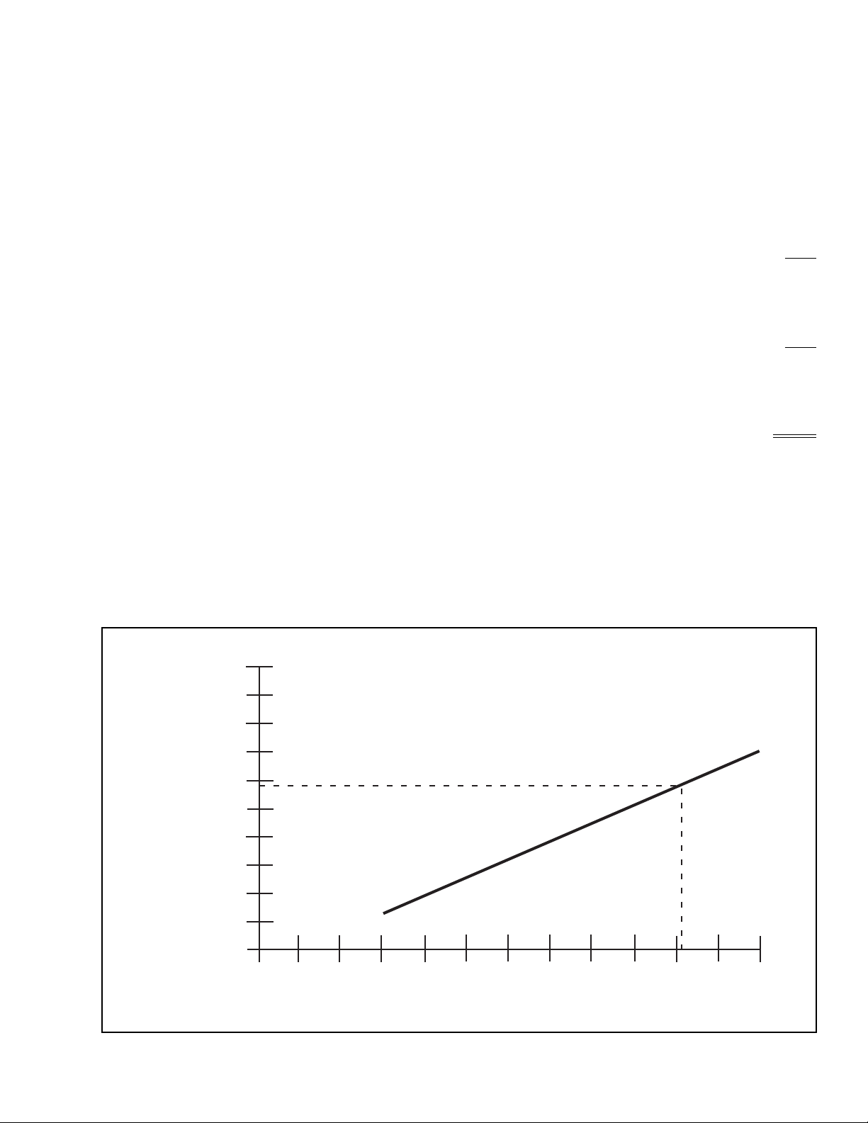
The regeneration volume is determined by how
much compressed air is pumped through the air
dryer during each compressor cycle. The following
chart shows the proper sizing of the system and
the volume of the reservoirs contributing to the
regeneration volume required for a given
installation. The “reservoirs contributing to
regeneration” will determine the placement of the
PCCV in the system. Since the air dryer will take
approximately 10 psi from the contributing
reservoirs, the volume for regeneration will be a
function of the reservoir sizes.
The “Total System Size” is the sum of all the air
tanks to be filled on all vehicles that the
compressor will be filling. For instance, if the
tractor has a total air system of 6000 in
3
(supply — 900 in
3
, primary 3200 in
3
, secondary
1900 in
3
) and it pulls a lead single trailer with
1400 in
3
, a single axle dolly with 1400 in
3
, and a
second single axle trailer with 1400 in
3
, the total
system size is 10,200 in
3
. Looking at the chart and
finding 10,200 in
3
at the bottom, reading up and
over shows the system needs 2856 in
3
of reservoir
volume contributing to regeneration. From this
volume,
≈
10 psi would be taken for regeneration.
In this case, installing the PCCV on the primary
tank gives adequate regeneration volume (supply
900 in
3
+ primary 3200 in
3
= 4100 in
3
).
Figure 8
.
Formula for Total System Size
Use the formula below to compute total
system size.
r
Total System Size = Sum of all reservoir tanks
an air compressor must service in the vehicle’s
air system
.
Example:
(IN
3
)
r
Supply (Wet) Tank 900
Primary Reservoir Tank 3200
Secondary Reservoir Tank 1900
Tractor’s Total Air System 6000
(IN
3
)
r
Lead Single Axle Trailer 1400
Single Axle Dolly 1400
Second Single Axle Trailer 1400
Total Load Pulled: 4200
r
Total Combination Vehicle
System Size (IN
3
)
The Air Compressor
Must Service 6000 + 4200 = 10,200
Figure 8
5000
4000
3000
2000
1000
0
Total reservoir volume — in3
0 5000 10,000
Volume of reservoirs contributing
to regeneration — in3

TP-92116
Revised 8-98 16579/Meritor
Page 8
© Copyright Meritor WABCO, 1998 Printed in the USA
Installing the Pressure-Controlled
Check Valve (PCCV)
NOTE
The pressure-controlled check valve replaces the
one-way check valve on either the secondary or
primary service reservoir. Use pipe sealant or
teflon tape on all air fittings.
1. Identify the appropriate service reservoir (see
above) and locate the one-way check valve at
the inlet. This reservoir is fed by the supply
(wet) tank and typically supplies air to the front
brakes and air-operated accessories. For more
information about the PCCV, please refer to
TP-9672,
Air Dryer Application Guidelines
.
NOTE
If the one-way check valve is internal or otherwise
inaccessible, locate the check valve on the
primary reservoir.
2. Remove and
discard
the one-way check valve
from the reservoir.
NOTE
The arrow located on the face plate of the PCCV
must point
TOWARD
the reservoir. Figure 9
.
3. Install the pressure-controlled check valve in
place of the check valve you discarded. If space
is limited, you can use a 45˚ or 90˚ pipe fitting.
4. Reconnect the supply line from the supply
(wet) tank to the inlet of the PCCV. Reroute or
shorten the air hose as necessary.
Check the Vehicle’s Air System for
an Alcohol Evaporator
NOTE
Typically, an alcohol evaporator will be installed in
the line between the air dryer and the supply (wet)
tank. Common installations are on the truck’s
firewall, on a frame rail and behind the cab.
However, an alcohol evaporator can also be found
at other locations.
1. Check the vehicle’s air system to determine if
an alcohol evaporator is installed.
2. If an alcohol evaporator is installed in the air
system, check for a bypass line connected to
the evaporator, as illustrated in
Figure 10
.
CAUTION
If a check valve is installed in the bypass line, the
air dryer will not function properly. Damage to the
system can result.
3. If a bypass line is connected to the evaporator,
check to see if a check valve is installed in the
bypass line. If check valve is installed:
a. remove the check valve from the
bypass line,
b. remove the bypass line and
c. replace the bypass line with 1/4-inch
nylon line.
4. If there is no bypass line installed at the alcohol
evaporator, install one using 1/4-inch nylon
line.
Figure 10
.
Figure 9
M
E
R
I
T
O
R
W
A
C
O
P
/
N
4
3
4
1
0
0
3
1
0
0
Figure 10
BYPASS LINE
LINE TO
SUPPLY TANK
ALCOHOL
EVAPORATOR
1/4"
NYLON
LINE
LINE TO
AIR DRYER

TP-92116
16579/Meritor Revised 8-98
Printed in the USA © Copyright Meritor WABCO, 1998
Page 9
Testing the System Saver 1000 and
1200 Series Air Dryers
1. Close the drain cocks on all reservoirs.
2. Start the vehicle. Wait for the air system to
reach full operating pressure.
3. If the air dryer exhausts air for 10-20 seconds
after the governor cuts out, it is
working correctly.
4. Apply vehicle brakes several times until the
compressor cuts in.
5. If the air dryer exhausts air for 10-20 seconds
after the compressor cuts out, it is
working correctly.
NOTE
One of the air pressure gauges on the vehicle
instrument panel will decrease by approximately
10 psi when the compressor cuts out and the air
dryer purges. This decrease is normal for the
System Saver 1000 and 1200 Series air dryers.
If the gauge does not decrease, recheck the
plumbing to ensure proper placement of the
pressure-controlled check valve.
Final Checks
1. Start the vehicle. Wait for the air system to
reach full operating pressure. When the
compressor cuts out, listen to the air dryer.
If either of the following conditions exist,
refer to Meritor WABCO Maintenance
Manual No. 34,
System Saver 1000 and 1200
Series Air Dryers
.
a. The air dryer continues to exhaust air for
longer than 30 seconds.
b. The air dryer does not exhaust air after
initial decompression.
2. Shut engine
OFF
. Apply a soap solution to each
connection that contains pressurized air:
a. If soap bubbles do not appear, connections
are sealed properly.
b. If soap bubbles appear:
r
Drain all reservoirs.
r
Remove leaking connection.
r
Inspect for damaged threads or cracks;
replace as necessary.
r
Apply pipe sealant or teflon tape to the
connection.
r
Repeat process.

TP-92116
Revised 8-98 16579/Meritor
Page 10
© Copyright Meritor WABCO, 1998 Printed in the USA

TP-92116
16579/Meritor Revised 8-98
Printed in the USA © Copyright Meritor WABCO, 1998 Page 11
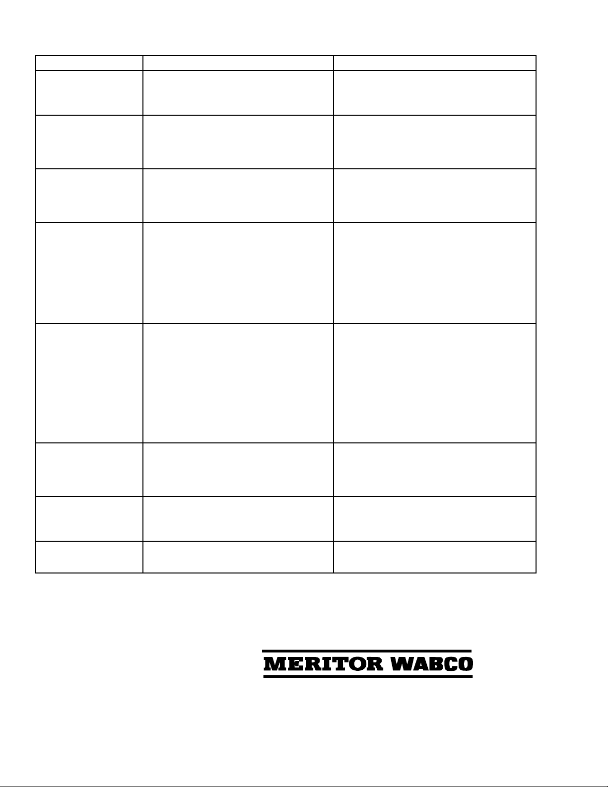
System Saver 1000 and 1200 Series Air Dryers Diagnostics
Condition Possible Cause Solution
Dryer leaks from purge
valve during compressor
loaded cycle. The leak
may cause excessive
compressor cycling or
prevent the system from
building air pressure.
Purge valve frozen open (cold weather
operation).
Debris under purge valve seat, such as particles
from fittings or air inlet line.
Purge valve washer installed upside-down.
Wrong air line connected to dryer port 4
(unloader port).
Purge valve snap ring not fully seated in groove.
Check heater. Repair/replace if necessary. Make
sure governor to dryer port 4 line is free of water/oil.
Removeandinspectpurgevalveandcleanwater/oil
from top of piston.
Disassemble and clean purge valve.
Remove cartridge and clean dryer sump area.
Ensure lip on aluminum washer faces down, away
from dryer.
Verify correct air line installation and correct as
needed.
Seat snap ring fully into groove.
Slight leak from purge
valve.Afterseveralhours,
the supply tank may be
empty.
Outlet check valve not seating or regeneration
valve not shutting off regeneration airflow. Remove, inspect, and clean outlet check valve and
regeneration valve diaphragm. Replace if worn or
damaged.
Regeneration cycle too
long (more than
30 seconds),
accompanied by loss of
pressure in the supply
tank.
Outlet check valve not seating.
Regenerationvalvenotshuttingoffregeneration
airflow.
Inspect and replace outlet check valve as needed.
Replace regeneration valve.
Regeneration cycle too
short (less than 10
seconds).
High air system demands during compressor
unloaded cycle.
Pressure-controlled check valve not installed in
system or not working properly.
One-way check valve installed in system
reservoir instead of, or with, pressure-controlled
check valve.
Regeneration valve not working.
Air governor not working properly.
Increase air system capacity or reduce air demands.
Check and replace pressure-controlled check valve
as needed.
Remove one-way check valve. Make sure pressure-
controlled check valve is installed correctly.
Remove regeneration valve and clean oil from
diaphragm. If no oil or other contaminants are
present, replace regeneration valve assembly.
Inspect per manufacturer’s instructions and repair/
replace as needed.
Noregenerationcycle.No
airflow from purge valve
after initial purge blast
(dryer decompression).
Air dryer not connected to supply tank or
connections reversed at dryer.
Regeneration valve not working.
One-way check valve installed in supply tank.
Alcohol evaporator installed between dryer and
supply tank.
Verify proper dryer installation per system diagram.
Replace regeneration valve.
Remove one-way check valve.
Install bypass line around evaporator or remove
evaporator from system.
Air dryer purges too
often, perhaps as
frequently as every
15seconds, accompanied
by excessive cycling of
the compressor.
Leak in line between governor and dryer port 4.
Leak in line between supply tank and governor.
Excessive air system leaks.
Excessive air system demands.
Outlet check valve not sealing.
Regeneration valve not shutting off properly.
Air governor has less than 16 psi range.
Leaking air compressor unloader(s).
Repair air line.
Repair air line.
Repair leaks.
Increase air system capacity or reduce air demand.
Inspect and replace outlet check valve as needed.
Replace regeneration valve.
Replace air governor.
Inspect compressor. Repair/replace per
manufacturer’s instructions.
Air dryer does not purge
when compressor
unloads (no blast of air
from purge valve).
Air line between governor and air dryer port 4
kinked or plugged.
Purge valve stuck closed.
Air governor not working properly.
Cut-out pressure never achieved by air
compressor.
Repair air line.
Replace purge valve.
Inspect air governor. Repair/replace per
manufacturer’s instructions.
Check for air leaks in system and repair as needed.
If no leaks in system, check compressor output.
Repair/replace per manufacturer’s instructions.
Air flows out of purge
valve entire time
compressor is unloaded.
Turbo cut-off valve not sealing. Replace turbo cut-off valve.
Meritor WABCO
Vehicle Control Systems
2135 West Maple Road
Troy, MI 48084 U.S.A.
800-535-5560
www.meritorauto.com
Information contained in this publication was in effect at the time the publication was approved for
printing and is subject to change without notice or liability. Meritor WABCO reserves the right to
revise the information presented or discontinue the production of parts described at any time.
© Copyright 1998
Meritor WABCO
All Rights Reserved Printed in the USA
Please Recycle
TP-92116
Revised 8-98
16579/Meritor
Rapid “spitting” of air
from purge valve in small
amounts. Frequency
varies with engine speed.
Holset E-Type compressor used, but non-1200E
dryer installed.
Compressor not completely unloading when
cut-out pressure is reached.
Replace air dryer with a System Saver 1200E air
dryer.
Inspect compressor. Repair/replace per
manufacturer’s instructions.
Air leak at turbo cut-off
valvevent.Holeburnedin
piston.
Temperature of air coming into dryer is too high
– not enough cooling takes place before dryer
inlet.
Move dryer farther from compressor. Add
additional compressor discharge line before air
dryer. Add cooling coil or heat exchanger before air
dryer.
NOTE: Inlet air temperature must not exceed 175°F.
Air leak at turbo cut-off
valve vent. Lip seal installed upside-down on piston. Lip
must face UP (towards dryer).
Valve bore worn excessively.
Install lip seal correctly.
Inspect valve bore for wear. If a new turbo cut-off
valve does not seal in a clean, lubricated bore,
replace the air dryer.
Air dryer frozen (water
collecting in base of dryer
is freezing).
No electrical power to heater connector.
Low voltage to heater connector.
Heater assembly not working.
Wrong voltage air dryer used; i.e., 12-volt air
dryer used in a 24-volt system.
Check for a blown fuse. Repair heater circuit.
NOTE: There must be power to the heater
connector the entire time the vehicle’s ignition is
“on.”
Repair cause of low voltage, such as poor electrical
ground, bad connections, corroded wire splices,
etc.
Replace heater assembly.
Replace with correct voltage air dryer.
No air pressure build-up
in system. Air dryer not plumbed correctly (connections
reversed).
Wrong air line connected to dryer port 4.
Air governor not working properly.
Air system leaks, such as compressor discharge
line, air dryer, reservoirs, brake or suspension
valves, etc.
Air dryer leaks from purge valve.
Ensure compressor discharge line is plumbed to air
dryer port 1, and air dryer port 21 is connected to
vehicle’s supply tank.
Ensure dryer port 4 line is connected to the “UNL”
port of the air governor.
Inspect governor per manufacturer’s instructions.
Repair or replace as needed.
Locate leak(s) and repair.
See purge valve conditions listed in this chart.
Water in tanks; often
following aftermarket
installation or when dryer
is a replacement for a
competitive brand.
Pressure-controlled check valve not installed in
correct tank or not installed at all.
Pressure-controlled check valve properly
installed, but one-way check valve not removed.
Installpressure-controlled checkvalve in secondary
tank.
Remove one-way check valve so that only the
pressure-controlled check valve is installed
between the secondary tank and supply tank.
Water, oil, or sludge in air
system tanks. Desiccant contaminated with oil.
Holset E-type compressor used, but non-1200E
dryer installed.
Replace desiccant. Inspect compressor per
manufacturer’s instructions.
Replace air dryer with a System Saver 1200E air
dryer.
Water in system tanks,
everything else checks
out okay.
Dryer not suitable for application. Review application guidelines. For assistance, call
Meritor Customer Support Center at
1-800-535-5560.
System Saver 1000 and 1200 Series Air Dryers Diagnostics (Continued)
Condition Possible Cause Solution
This manual suits for next models
1
Table of contents
Other Meritor Wabco Automobile Accessories manuals

Popular Automobile Accessories manuals by other brands

Cruz
Cruz Evo Rack Alu A23-140 Assembly instructions

Schaudt
Schaudt CSV 416 operating instructions

ARKSEN
ARKSEN 002-AU-19CC owner's manual

Classic Accessories
Classic Accessories StormPro RainProof Instructions & Care

Subaru
Subaru H001ssC800 installation instructions

Connects2
Connects2 Vision CAM-4 user manual


