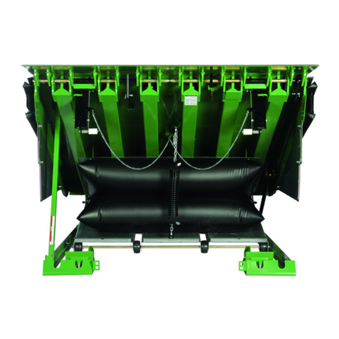
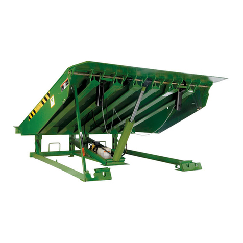
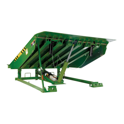
Kelley aFX User manual


Optional Blue Contact Block
(Normally Closed)
Field Installed (Low Voltage Only)
See Supplied Mfg. Instructions
Control
Station
Control
Station
Optional connection to restraint
Star4 LA terminals C and 17.
For Star4 module with 403 controller
use 21 and 22
To: Auto chock terminal block
terminals no. 5 and no. 24
Pit Wall
Receptacle
NEMA 5-15R
(By Others)
Pit Wall
Receptacle
NEMA 5-15R
(By Others)
1 Phase 120V
50/60 Hz
1 Phase 120V
50/60 Hz
BLK
WHT
GRN Motor
BLK
WHT
GRN Motor
Circuit Breaker
(By Others)
20 AMP MAX
Circuit Breaker
(By Others)
20 AMP MAX
Line
Line
Grn
Grn
Neutral
Neutral
120V
1 Phase
50/60 Hz
120V
1 Phase
50/60 Hz
120V, Single Phase, 50/60 Hz
Optional Dual Contact
120V, Single Phase, 50/60 Hz
Single Contact

Maintenance
strut bracket
Insert hairpin
clip through
maintenance
strut pin
Maintenance
strut pin
Lip
lock
Lip
Insert
hairpin
clip into
lip lock
Ramp
Maintenance
strut


Pan Rollers
16" or *19"

Pit Floor
Hanger bracket
Swing link
Notch Roller
Dock leveler ramp
Connecting rod
Lip
Center bolt
Push Bar

123
Lip Size Lip Capacity
25K 30K & 35K 40K, 45K, & 50K
6'-16" Hole 3 Hole 2 Hole 1
6'-18" Hole 2 Hole 1 Hole 1
6'-20" Hole 1 Hole 1 Hole 1
6-1/2'-16" Hole 2 Hole 1 Hole 1
6-1/2'-18" Hole 1 Hole 1 Hole 1
6-1/2'-20" Hole 1 Hole 1 Hole 1
7'-16" Hole 2 Hole 1 Hole 1
7'-18" Hole 1 Hole 1 Hole 1
7'-20" Hole 1 Hole 1 Hole 1
Lip Size Hole
ALL CAPACITY
6'-16" Hole 3
6'-18" Hole 2
6'-20" Hole 1
6-1/2'-16" Hole 3
6-1/2'-18" Hole 2
6-1/2'-20" Hole 1
7'-16" Hole 3
7'-18" Hole 2
7'-20" Hole 1
aFX Model aFX-S Model
123

Dock Level
Support Leg
BDC
Chain

aFX_ _ x _
Length
6 = 6' long
8 = 8' long
10 = 10' long
Width
6 = 6' wide
6.5 = 6-1/2' wide
7 = 7' wide
-S
Optional Safety Lip
6 x 6 72 63
6 x 8 72 87
6 x 10 72 111
6.5 x 6 78 63
6.5 x 8 78 87
6.5 x 10 78 111
7 x 6 83 63
7 x 8 83 87
7 x 10 83 111
W
L
Pit depth
20" or 24"
Lip length
16", 18", Or 20"

20
2
3
17
16
16
6
5
23
4
9
39
Note: Rivets (Item 40)
Attach Bag Shield (Item 39)
To Brackets Welded On
Bottom Of Ramp.
40
15
15
21
7
7
8
8
10
10
22
28
11
12
13
14
27
25
24
42
30
41
31
18
35
37
36
33
32
34
24
38
26
29

2
3
4
15
1
17
19
7
6
5
7
8
8
10
10
11 12
13
14
15
39
40
20
23
9
21 22
28
26
29
27
25
24
30
41
3118
42
Note: Rivets (Item 41)
Attach Bag Shield (Item 40)
to Brackets Welded on
Bottom of Ramp.
35
37
36
33
32
34
24
16
16
38


1
3
4
2
5
7
68
1
3
4
The mounting angle is connected
to the center air bag support pan.
Excess chain can hang
free or be cut off
The upper shackle is connected to
the ring next to the chain cup.
Link location
(see chart) 8' 50k levelers do not use
the same location as lower
capacity units. Incorrect
positioning will result in
damage to the spring.

10
11
2
3
6
7
5
12
4
8
9
13
14
12
15
Note: Items 5 - 8 included in item 2.

1
2
4x
4x
2x 2x
2x
6x
6x
6x

5
8
16
13
12 61
71
15
3
8
5
11
8
8
9
6
1
14
10
2
10
5
4
15
10

3
8
9
10
7
4
16
20
19 18 17
4
12
13
14
5
FOR
SHIPPING
ONLY
11
2
15
15
1
6
15
15


7
1
5
6
2
3
4
For use with interlock applications on STAR® 4 and AUTO CHOCK® vehicle restraints.
This manual suits for next models
1
Table of contents
Other Kelley Lifting System manuals
Popular Lifting System manuals by other brands

AMSAN
AMSAN AM-FPL9 manual

Challenger Lifts
Challenger Lifts CL4P9S Installation, operation & maintenance manual

Schmalz
Schmalz VACUMASTER COIL operating instructions

Aqua Creek Products
Aqua Creek Products EZ Series manual

IDEAL
IDEAL MSC-6KLP Installation & operation manual

Grabo
Grabo OTTOVAC Operator's manual

Braun Corporation
Braun Corporation NL500 Series Service manual

EINHELL
EINHELL BT-PT 2500 Original operating instructions

Skyjack
Skyjack SJIII 6826E operating manual

WPG
WPG P1HV1102DC3 operating instructions

Launch
Launch TLT235 user manual

Safety Clamps
Safety Clamps VL-BC Operation, maintenance, and repair manual