SpiderAlert SR-500 User manual
DE3211 3-11
SR
SRSR
SR-500
-500-500
-500, SR
, SR, SR
, SR-500
-500-500
-500 ER
ERER
ER
SpiderAlert Wireless Receiver Installation Instructions
1
11
1. INTRODUCTION
. INTRODUCTION. INTRODUCTION
. INTRODUCTION
SR-500 wireless receiver is as an interface unit between various
SpiderAlert wireless transmitters and the SpiderBus.
SR-500 ER is the extended range version of the SR-500. It has
the following features:
• Higher receiver sensitivity that enables longer communication
range.
• Improved receiver selectivity (narrower bandwidth) that
prevents reception of interfering signals from undesired
transmitters (whose frequencies are near the receiving
frequency).
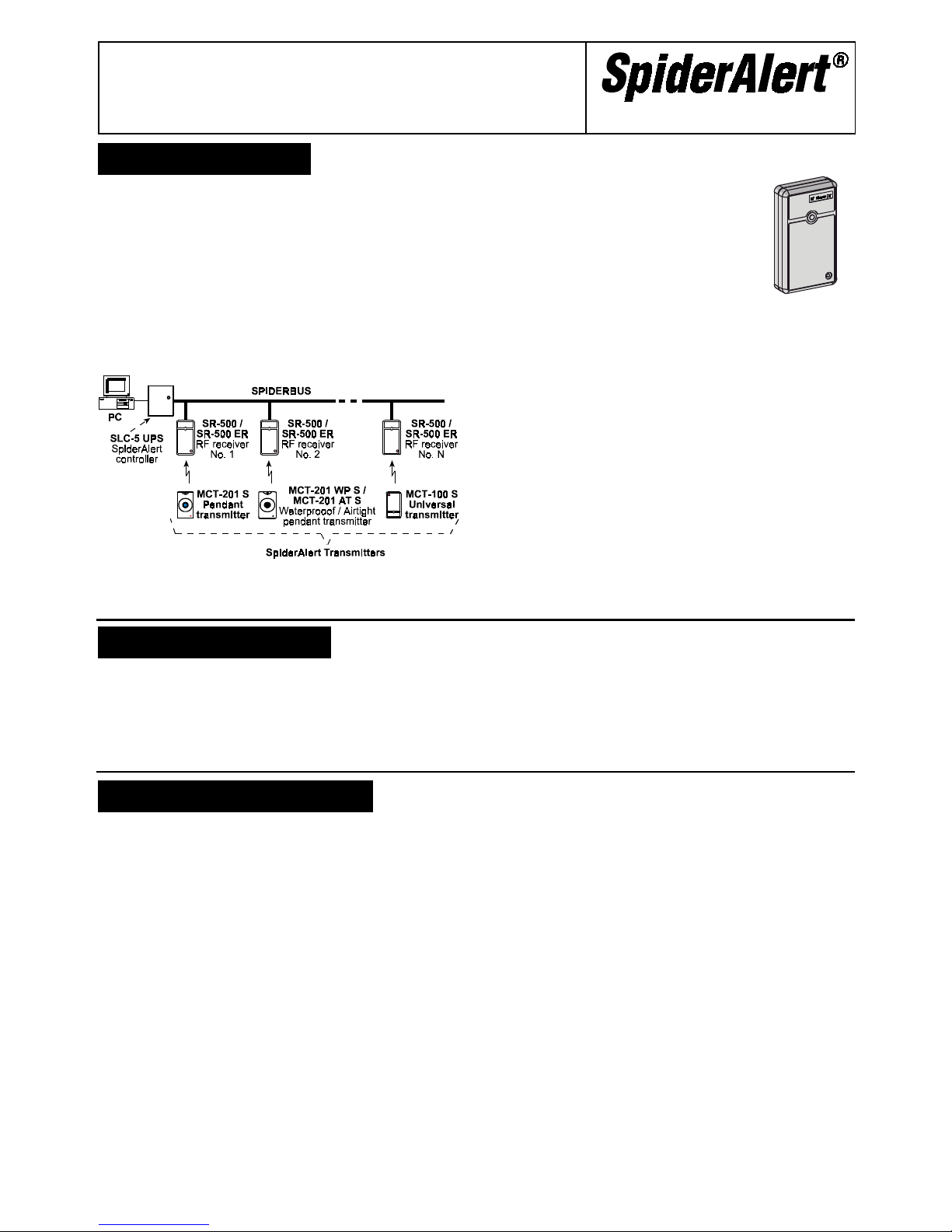
SR-500 (ER) receives RF signals from SpiderAlert transmitters
and relay the signals to the SpiderAlert Local Controller SLC-5
via the SpiderBus. All data collected by the SLC-5 is transferred
to the head end computer for further processing (see fig. 1-1).
Figure 1-1. SR-500 (ER) in the SpiderAlert System
Each receiver has a factory-programmed, 8-bit ID number (in a
2-digit hexadecimal form) that is marked on top of its
microprocessor IC.
Attendance reports with the receiver ID
number are sent by each receiver to the
SLC-5 at regular intervals, thus permitting
continuous supervision over the entire
receiver network (see Para. 3-2).
SR-500 (ER) also responds to command
signals sent from the computer via the SLC-5
controller and SpiderBus. Each command
signal is addressed to a specific receiver, for
controlling one of its two output circuits.
Figure 1-2.
External View
This allows the attendant at the head end to control remote
equipment such as sirens, lights or automatic voice announcers,
that can be turned on and off by direct connection to receiver’s
output or via a relay.
The receiver can be remotely programmed from the SpiderAlert
main station - programming of the receiver ID number and the
duration of its outputs 1 and 2 signals in “pulse” operation mode.
The receiver is protected against tampering by an on board
tamper switch that is actuated upon removal of the front cover.
Once tampered with, the receiver sends out its ID code plus a
special tamper code to the head end computer.
A sensitivity control (marked RANGE, see fig. 4.3) is provided on
the printed circuit board, to enable reception range adjustment.
A terminal block at the top (see fig. 4.3) provides a 4-wire
connection to the SpiderAlert bus and two output terminals for
controlling external devices (for details, refer to para. 3-3). A
right-hand side terminal block (fig. 4.3) provides 3 input terminals
for reporting local alarms (for details, refer to para. 3-4).
When a deliberate (or accidental) jamming signal is received, the
receiver sends a jamming alert message.
2
22
2. SPECIFICATIONS
. SPECIFICATIONS. SPECIFICATIONS
. SPECIFICATIONS
Operating Frequency (MHz): 315, 404, 418, 433.92 or other
frequencies according to local requirements.
Receiver ID Code: 1 of 255 possible codes, factory programmed
Data Transfer to Bus: Serial, software controlled.
Operating Voltage Range: 10 - 16 VDC.
Number and type of Inputs: 3, Normally closed (NC)
Number of Outputs: 2
Open Collector Output Current Sinking Capability: 100 mA.
Current Consumption @ 13.6 V:
SR-500: 7.2 mA (Standby), 8.8 mA (in operation)
SR-500 ER: 37 mA (standby), 39 mA (in operation)
Operating Temperature Range: 0°C to 49°C (32°F to 120°F).
Dimensions (H x W x D): 110 x 63 x 25 mm (4-5/16 x2-1/2 x 1 in.)
Weight: SR-500 - 80g (2.8 oz.), SR-500 ER - 78g (2.75 oz.)
3
33
3.
..
. OPERATION ROUTINE
OPERATION ROUTINEOPERATION ROUTINE
OPERATION ROUTINE
3.1 Message Handling
When a coded message is received from SpiderAlert transmitter,
the receiver registers it and checks whether the bus is busy. If so,
the receiver pauses to prevent collision of its message with other
messages, and then tries again. If the bus is free, the receiver
reports the transmitter's ID code, be it 12-bit or 24-bit,
accompanied by its own 8-bit ID number.
Once the message is received by the SLC-5, an "acknowledge"
signal is returned to the receiver, causing it to stop sending the
data. If there is no response from SLC-5, the receiver will keep
sending the data repeatedly, until SLC-5 returns an
acknowledgement. The receiver will not be free to receive new
coded transmissions until it gets this acknowledgement.
A special on-board LED lights upon reception of a valid RF
signal. It will remain illuminated while the receiver is engaged in
sending the message via the data bus or while the receiver is
waiting for an acknowledge signal from SLC-5. The LED turns off
5 seconds after reception of acknowledge signal from the SLC-5.
3.2 Supervision Method
The receiver is programmed to send out periodic attendance
messages. An attendance message consists of the receiver's ID
number and a special test code identifying the message as an
attendance report. Once the SpiderAlert network is powered up,
all receivers on the bus go through the first cycle of attendance
reports. The SLC-5 automatically "learns" the participating units'
ID numbers, registers their IDs and creates a supervision list.
After the first reporting cycle, the SLC-5 will expect regular
attendance reports from each unit on its list.
Attendance reports received at regular (correct) intervals are
acknowledged by the SLC-5 but not displayed by the head end
computer. However, attendance reports received for the first time
or after a break in communication between the receiver and the
SLC-5 will be displayed on the head end computer screen.
If an attendance report from a specific receiver fails to come in
within 4 minutes from the last report, a warning appears on the
computer's monitor. If attendance reports from a certain receiver
or from a group of receivers stop, the reason might be SpiderBus
discontinuity (an "open" bus), receiver failure or sabotage.
3-12 DE3211
3.3 Output Control
The SR-500 (ER) provides two output terminals (OUT1 and
OUT2). These terminals, that are of the open-collector type, are
under control of the head-end software - they can be activated
(pulled LOW) and deactivated manually or by automatic computer
command. Each output may be used to sound an alarm, to switch
lights on and off, to open a door controlled by an electrical door
strike, or for many other tasks. Since each open collector output
can not sink more than 100 mA, an interface relay might be
required for operating external devices, as shown in Figure 4-4.
3.4 Reporting Local Alarms
The SR-500 (ER) provides 3 input terminals with a common
ground return on a separate terminal block. The input circuits,
which are of the normally closed type, may be connected to
motion, smoke or glass break detectors in the immediate vicinity
of the unit for reporting local alarms via the SLC-5 to the
head-end computer. The computer software identifies the
receiver that sent out the alarm signal and the specific input of
origin. Consecutively, a suitable message appears on the
computer's monitor and the alarm is registered in the event log.
4
44
4. INSTALLATION
. INSTALLATION. INSTALLATION
. INSTALLATION
4.1 Preliminary Survey
Taking into account that the coverage
areas of individual receivers should
overlap a little, to prevent creation of
"dead" spots in-between neighbouring
units. It is therefore recommended to
conduct a survey of the installation
site as follows:
A. Prepare a test equipment set
consisting of an SLC-5, several
SR-500(ER) receivers, a power
supply unit, a 4-lead cable reel
and at least one type of
transmitter.
Note: Make sure the sensitivity
control in each receiver is set
halfway between MAX. and MIN.
Depress the tamper switch lever
and capture it in this position with
masking tape.
B. Place the SLC-5 in a convenient
location and temporarily deploy a
few receivers at "strategic"
reception points throughout the
coverage area.
Figure 4-1.
Temporary Bus
C. Use the 4-lead cable to form a temporary bus that inter
connects all receiver units and SLC-5, as shown in Fig. 4-1
(also refer to Para. 5-1, Steps A and B). The cable may be
put down on the floor, following the shortest possible path.
D. Power up the test equipment using the 12 VDC power supply
or a 12 V battery (see Figure 4-1).
E. Operate a SpiderAlert transmitter in various locations within
the receiver's expected coverage area to test the reception
range. Reception is verified when the LED lights steadily in
response to each transmission, until the SLC-5 acknowledges
the message.
IMPORTANT: Remember that different transmitter models
have different power outputs. It is therefore advisable to
make this test with all transmitter models likely to be used in
the vicinity of the tested receiver.
F. If "dead" or marginal reception areas are discovered:
• Move the receiver to a point where reception is better.
• Rotate the sensitivity control towards MAX to increase the
receiver's sensitivity.
• Move the neighboring receiver closer, to bridge the
reception gap.
G. If the receiver is picking up transmissions made in a
neighboring area:
• Move the receiver away from the neighbouring area to
decrease the coverage overlap.
• Rotate the sensitivity control towards MIN to decrease the
receiver's sensitivity.
• Coil the antenna wire (use a small screwdriver's stem for
forming the coil) to reduce the reception range.
H. Repeat Steps E through G above for all other receivers.
Make a list of the chosen locations and indicate special
requirements (sensitivity control position, coiled antenna, etc.).
Note: To determine the point from which an alert transmission
was made with greater accuracy, dual technology (RF/IR)
receivers and transmitters should be used. This especially
applies to multi-story buildings.
4.2 Mechanical Mounting
Note: If it is necessary to install the receiver in a metal
enclosure, let the antenna wire out through a hole or a slot in the
metal enclosure, and test the reception ability very carefully.
A. Open the receiver box.
B. Open the two mounting
knockouts in the base.
C. Hold the base, against the
mounting surface, with the
antenna wire hanging
down.
D. Mark points for drilling, put
the unit aside and drill the
mounting holes. Attach the
unit to the mounting surface
using two screws and wall
anchors (if required).
Knockouts that serve as
wiring outlets are provided
at the top of the base.
SR-500(ER) may be connected
to the SpiderBus via 4
terminals (Fig. 4-4) or via
telephone type RJ-11
connector.
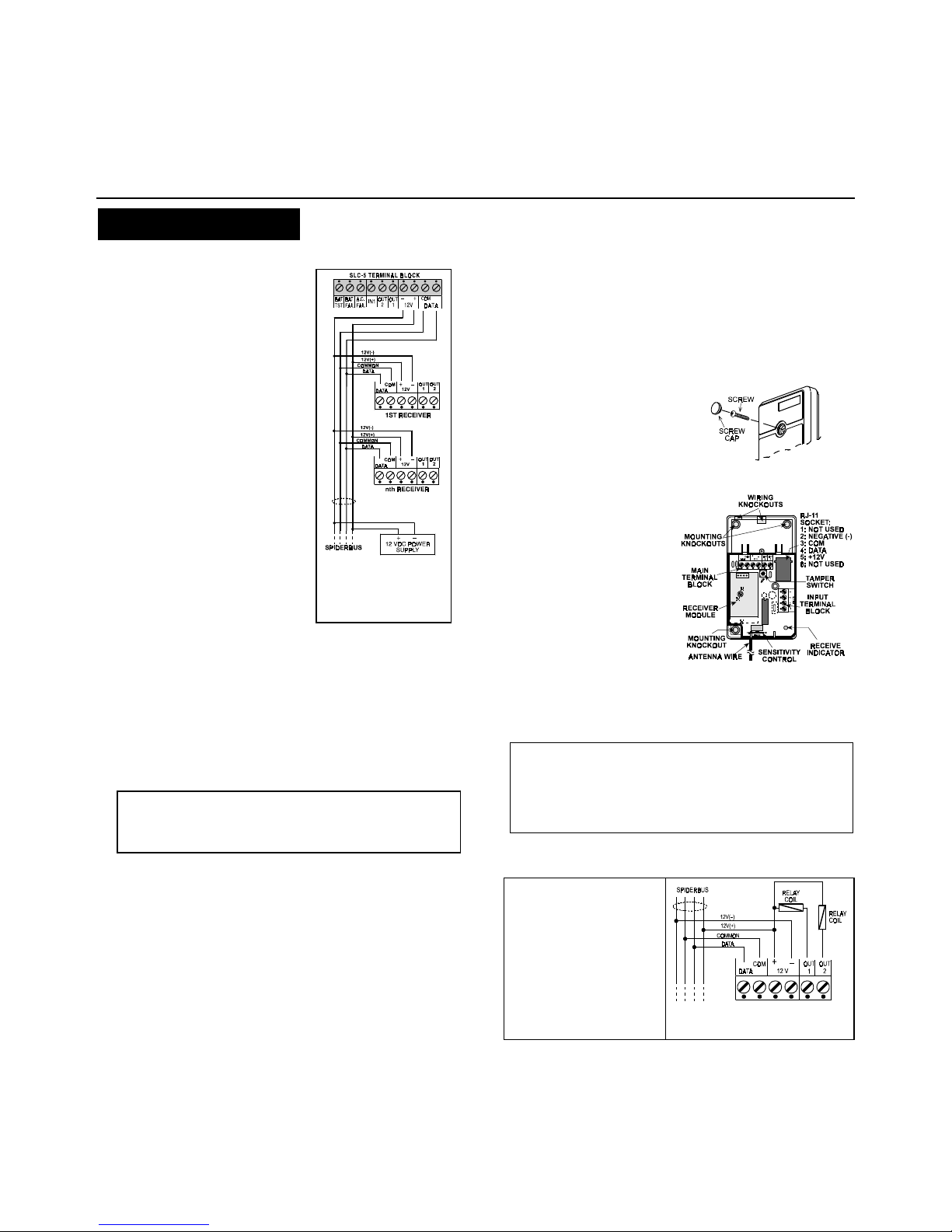
Figure 4.2 Cover Removal
Figure 4.3 Internal View
4.3 Terminal Block Wiring
A. Connect the data wires of the bus to the DATA terminals on
the receiver's terminal block.
CAUTION! One of the data terminals is marked COM,
indicating connection to the common (negative) lead of the
data bus. The other terminal marked DATA must be
connected to the second lead of the data bus. As long as the
data bus is free, the data lead is kept HIGH by a pull-up
resistor in the SLC-5 Local Control Unit.
B. Connect the power supply bus wires to the 12 V(+) and (–)
terminals.
Caution: Make sure not to reverse the bus wires!
Attention! With a large
number of receivers on the
bus, individual power
supplies may be used for
each group of receivers.
Refer to Para. 4-4 in SLC-5
installation manual
(D-7115-0), where several
examples are given for
power supply distribution
along the bus.
Figure 4-4. Bus, Power and
Output Terminal Block Wiring
Auxiliary power supply PS-2 and bus repeater SRP-51 are
available for long buses (refer to installation manuals).
C. Either output terminal is suitable for operating a low-current
12VDC buzzer, an LED, or an auxiliary relay that draws less
than 100 mA current. In case of a relay, connect its operating

DE3211 3-13
coil across the OUT1 and 12 V(+) or OUT2 and 12 V(+)
terminals (as shown in Figure 4-4).
Relays connected to OUT1 and OUT2 will pull in by manually
entered or automatic command received from the head end
computer. Relay contacts may be wired to open or close
doors, to control lighting fixtures, to sound an alarm, to switch
a wireless transmitters or CCTV on and off, etc.
D. If you wish to report up to 3
kinds of local alarms to the
head-end computer, connect
normally closed (N.C.) sensor
contacts across the alarm
inputs and the ground (–)
terminal, as shown in Fig. 4-5. Figure 4-5. Input
Terminal Block Wiring
Remember: Unused inputs should be bridged to the ground
terminal with a short jumper wire, or else they will constantly
initiate an alarm.
4.4 Bus Connection via RJ-11
If you prefer the quick attach/detach feature of telephone-type
connectors, you can wire the SpiderAlert bus to the receiver
using the on-board TELCO socket. The 4-pin mating plug
required is designated RJ-11 and commonly called "TELCO plug"
(see Figure 4-6). Prepare the following items:
• An appropriate length of a 4-lead color-coded modular cable,
for producing a patch cord between the bus port of the
SR-500(ER) and the bus junction box (see Figure 4-6).
• Two 4-position RJ-11 plugs, to terminate the above mentioned
patch cord.
• A crimping tool for 4-position RJ-11 plugs.
Figure 4-6. RJ-11 plug
A. Identify the bus 4 wires and connect them to the numbered
terminals within the junction box, maintaining the order
required for correct patching.
B. Prepare RJ-11-
to-RJ-11 patch cord,
long enough to
bridge the distance
between the bus
junction box and
SR-500(ER). Make
sure a "one-for-one"
configuration is
obtained - pin 2 is
connected to pin 2,
pin 3 to pin 3, etc.
Figure 4-7. Bus Connection via a
Junction Box
4.5 Final Calibration and Test
IMPORTANT! Before testing, verify that the SLC-5 Local
Control unit is active. If the SLC-5 is inactive, any receiver
sending a message to it will become "hung up" indefinitely, until
the message is acknowledged.
Having conducted a preliminary survey as instructed in Para. 4-1,
and having mounted receivers at the chosen locations, a final
test is only needed to make sure that the system functions well at
the outer edges of the coverage area.
A. Make sure the sensitivity control in each receiver is set as
determined during the preliminary survey. Also coil the
antenna wire wherever necessary according to your "special
requirement" list. Leave receiver covers off for the time being.
B. Temporarily disconnect all receivers from the bus by
disengaging the RJ-11 plugs.
C. Reconnect the receivers one by one. The head-end computer
should register an "attendance report" and a "tamper alert",
but the receiver's LED will light only once - while sending the
tamper alert.
D. Operate a SpiderAlert transmitter in various locations within
the receiver's coverage area to test the reception range,
beginning at the outer edges of the area to be covered.
Reception is verified when the LED lights steadily in response
to each transmission, until the SLC-5 acknowledges the
message. Readjust the sensitivity if necessary.
IMPORTANT: Do not leave the installation site before
verifying reliable reception all through the expected
coverage area.
5. PERIODIC INSPECTION
The supervision feature of the SpiderAlert system allows the
monitoring personnel to detect a disconnected data bus or a
receiver that fails to perform its data transfer duties.
This supervision, however, does not cover the RF communication
part of the process. If the receiver's RF section malfunctions, the
receiver will continue to send out regular attendance reports, but
will not be able to receive wireless transmissions. For this reason,
the system manager should make provisions for testing the
system periodically without alarming the monitoring personnel, as
suggested in Para. 5-1 below. Individual transmitter holders
(system users) should test their transmitters periodically without
involving the monitoring personnel. This can be carried out as
suggested in Para. 5-2. below.
5.1 Testing by the System Manager
To ensure unfailing operation of the system, the system manager
is advised to act as follows:
A. Define one or several transmitters as test units and ask the
monitoring personnel to link a test message to these
transmitters' ID numbers in the computer's data base.
Transmissions received from these test transmitters will be
registered in the on-screen event log but will not be
considered an alert.
B. Use a test transmitter to test all receivers at least once a
week by initiating a transmission in the coverage area of each
receiver. Watch the receiver's LED light in response to your
transmission and go off once the message is acknowledged.
C. Check the monitoring station event log and verify that all test
transmissions were duly registered by the system's computer.
D. Call the installation company and report any receiver that
failed to send a message to the computer.
5.2 Testing by Individual Users
Any SpiderAlert site may be easily equipped for transmitter tests
by individual users:
A. Create a special test station, well away from the coverage
area of all other receivers.
B. Define a receiver as a test unit, install it inside a metal box,
set its sensitivity control to MIN. and coil its wire antenna
tightly around the stem of a small screwdriver.
C. Drill a small hole in the metal box and insert a green LED into
the hole. Wire the LED with 1k½ resistor in series across the
test unit's OUT1 and 12 V+ terminals. The computer can be
programmed to respond to messages received from the test
unit by momentary activation of output No. 1 of the test unit.
D. Ask the monitoring station personnel to link a test message to
the test unit's ID number in the computer's data base. Any
message collected from this receiver will thereby be
considered a test message.
E. Inform all users of the test station, and instruct them to test
their transmitters periodically at close range. Green LED
momentary illumination, in response to each transmission,
serves as an assurance that the test has been successful.

3-14 DE3211
6. MISCELLANEOUS COMMENTS
6.1 Product Limitations
The SpiderAlert wireless system is very reliable and is tested to
high standards. However, due to low transmitting power and
limited range (required by FCC and other regulating authorities),
there are some limitations to be considered:
A. Receivers may be blocked by radio signals near their
operating frequencies, regardless of digital code used.
B. Receiver can only respond to one transmitted signal at a time.
C. Wireless equipment should be tested regularly to determine
whether there are sources of interference and to protect
against faults.
6.2 Standard Compliance
A. The user is cautioned that changes or modifications to the
unit, not expressly approved by Visonetix Ltd., could void the
user's FCC or other authority to operate the equipment.
B. The 315 MHz model of this device complies with Part 15 of
the FCC Rules and RSS-210 of Industry and Science
Canada. Operation is subject to the following two conditions:
(1) This device may not cause harmful interference, and (2)
this device must accept any interference received, including
interference that may cause undesirable operation.
C. 418 MHz and 433.92 MHz receiver’s models comply with CE
requirements for Europe and bear CE mark and certification.
Appendix A. Heated Enclosure for Cold Regions
Whenever SR-500 (ER) is installed outdoors in cold regions, it
becomes necessary to protect the sensitive electronics from exposure
to temperatures below 0°C (32°F). The enclosure available for this
purpose is Carlon model CJ-863, in which a heater kit is installed (see
Figure A-1).
Mount the SR-500(ER) within the heated enclosure as follows:
1. Use some hot glue or double sided tape to attach the receiver box
to the cover, as shown.
2. Bend the antenna wire and fix it to the cover, using some hot glue.
Install the heated enclosure and complete the wiring as follows:
1. Mount the fully equipped enclosure on the wall.
2. Wire the receiver as instructed in Section 4 of this manual.
3. Connect 24 VAC / 1.7A transformer to heating element terminals.
Note: When using 18 AWG wire, do not exceed 30m (100 ft) wire
length between the AC transformer and the heating element.
When using 12 AWG wire, do not exceed 90m (300ft) wire length.
Figure A-1. Internal Construction of the Heated Enclosure
4. Test the receiver according to para. 5.
5. Shut the heated enclosure tight and test reception range again.
WARRANTY
Visonetix Ltd., and its affiliates, (hereinafter collectively referred to as "the
Manufacturer") warrants its products (hereinafter referred to as "the Product”) to be free
of defects in materials and workmanship under normal operating conditions and use for
a period of one year from the date of shipment by the Manufacturer. The Manufacturer's
obligations shall be limited within the warranty period, at its option, to repair or to replace
the defective Product or any defective component or part thereof. To exercise this
warranty, the product must be returned to the manufacturer freight prepaid and insured.
This warranty does not apply to repairs or replacement caused by improper installation,
Product misuse, failure to follow installation or operating instructions, alteration, abuse,
accident, tampering, repair by anyone other than the Manufacturer, external causes, and
failure to perform required preventive maintenance. This warranty also does not apply to
any products, accessories, or attachments used in conjunction with the Product,
including batteries, which shall be covered solely by their own warranties, if any. The
Manufacturer shall not be liable for any damage or loss whatsoever, whether directly,
indirectly, incidentally, consequentially or otherwise, resulting from a malfunction of the
Product due to products, accessories, or attachments of others, including batteries, used
in conjunction with the Product.
THE MANUFACTURER MAKES NO EXPRESS WARRANTIES EXCEPT THOSE
STATED IN THIS STATEMENT. THE MANUFACTURER DISCLAIMS ALL OTHER
WARRANTIES, EXPRESS OR IMPLIED, INCLUDING WITHOUT LIMITATION IMPLIED
WARRANTIES OF MERCHANTABILITY AND FITNESS FOR A PARTICULAR
PURPOSE. THE MANUFACTURER’S SOLE RESPONSIBILITY FOR WARRANTY
CLAIMS IS LIMITED TO REPAIR OR TO REPLACE AS SET FORTH IN THIS
STATEMENT.
The Manufacturer shall have no liability for any death, personal injury, property damage,
or other loss whether direct, indirect, incidental, consequential, or otherwise, based on a
claim that the Product failed to function. However, if the Manufacturer is held liable,
whether directly or indirectly, for any loss or damage arising under this limited warranty
or otherwise, regardless of cause or origin, the Manufacturer's maximum liability shall be
limited to the purchase price of the Product, which shall be fixed as liquidated damages
and not as a penalty, and shall be the complete and exclusive liability of the
Manufacturer.
The Manufacturer shall not, under any circumstances whatsoever, be liable for any
inaccuracy, error of judgment, default, or negligence of the Manufacturer, its employees,
officers, agents, or any other party, or of the purchaser or user, arising from any
assistance or communication of any kind regarding the configuration, design, installation,
or creation of security system involving the Product, that being the responsibility of the
purchaser or user.
If the Manufacturer is unable to make such repair or replacement, the Manufacturer’s
entire liability shall be limited to the cost of a reasonable substitute product.
The Manufacturer shall not be responsible for any dismantling, installation, reinstallation,
purchasing, shipping, insurance, or any similar charges.
The Manufacturer shall have no liability for any damages, including without limitation, any
direct, indirect, incidental, special, or consequential damages, expenses, costs, profits, lost
savings or earnings, or other damages arising out of the use of the Product or the removal,
installation, reinstallation, repair or replacement of the Product or any related events. In the
event that there is any liability against the Manufacturer, such liability shall be limited to the
purchase price of the Product which amount shall be fixed as liquidated damages.
The purchaser and user understand that this Product may be compromised or circumvented
by intentional acts; that the Product will not in all cases prevent death, personal injury,
property damage, or other loss resulting from burglary, robbery, fire or other causes; and
that the Product will not in all cases provide adequate warning or protection. The purchaser
and user also understand that a properly installed and maintained alarm may reduce the risk
of events such as burglary, robbery, and fire without warning, but it is not insurance or a
guarantee that such events will not occur or that there will be no death, personal injury,
property damage, or other loss as a result of such events.
By purchasing the Product, the purchaser and user shall defend, indemnify and hold the
Manufacturer, its officers, directors, affiliates, subsidiaries, agents, servants, employees,
and authorized representatives harmless from and against any and all claims, suits, costs,
damages, and judgments incurred, claimed, or sustained whether for death, personal injury,
property damage, or otherwise, because of or in any way related to the configuration,
design, installation, or creation of a security system involving the Product, and the use, sale,
distribution, and installation of the Product, including payment of any and all attorney’s fees,
costs, and expenses incurred as a result of any such events.
The purchaser or user should follow the Product installation and operation instructions and
test the Product and the entire system at least once each week. For various reasons,
including but not limited to changes in environmental conditions, electric, electronic, or
electromagnetic disruptions, and tampering, the Product may not perform as expected. The
purchaser and user are advised to take all necessary precautions for the protection and
safety of persons and property.
This statement provides certain legal rights. Other rights may vary by state or country.
Under certain circumstances, some states or countries may not allow exclusion or limitation
of incidental or consequential damages or implied warranties, so the above exclusions may
not apply under those circumstances and in those states or countries.
The Manufacturer reserves the right to modify this statement at any time, in its sole
discretion without notice to any purchaser or user. However, this statement shall not be
modified or varied except by the Manufacturer in writing, and the Manufacturer does not
authorize any single individual to act on its behalf to modify or vary this statement.
Any questions about this statement should be directed to the Manufacturer.
VISONETIX LTD. (ISRAEL): P.O.B 22020 TEL-AVIV 61220 ISRAEL. PHONE: (972-3) 645-6890, FAX: (972-3) 645-6891
VISONIC SYSTEMS INC. (U.S.A.): 10 NORTHWOOD DRIVE, BLOOMFIELD CT. 06002-1911. PHONE: (860) 242-9945, (800) 874-3989 FAX: (860) 242-0191
VISONIC LTD. (UK): UNIT 1, STRATTON PARK, DUNTON LANE, BIGGLESWADE, BEDS. SG18 8QS. PHONE: (01767) 600857 FAX: (01767) 601098
VISONETIX LTD. 1999 SR-500, SR-500 ER D-3211-0, NEW: DE3211- (REV. 5, 12/99)
This manual suits for next models
1
Table of contents


