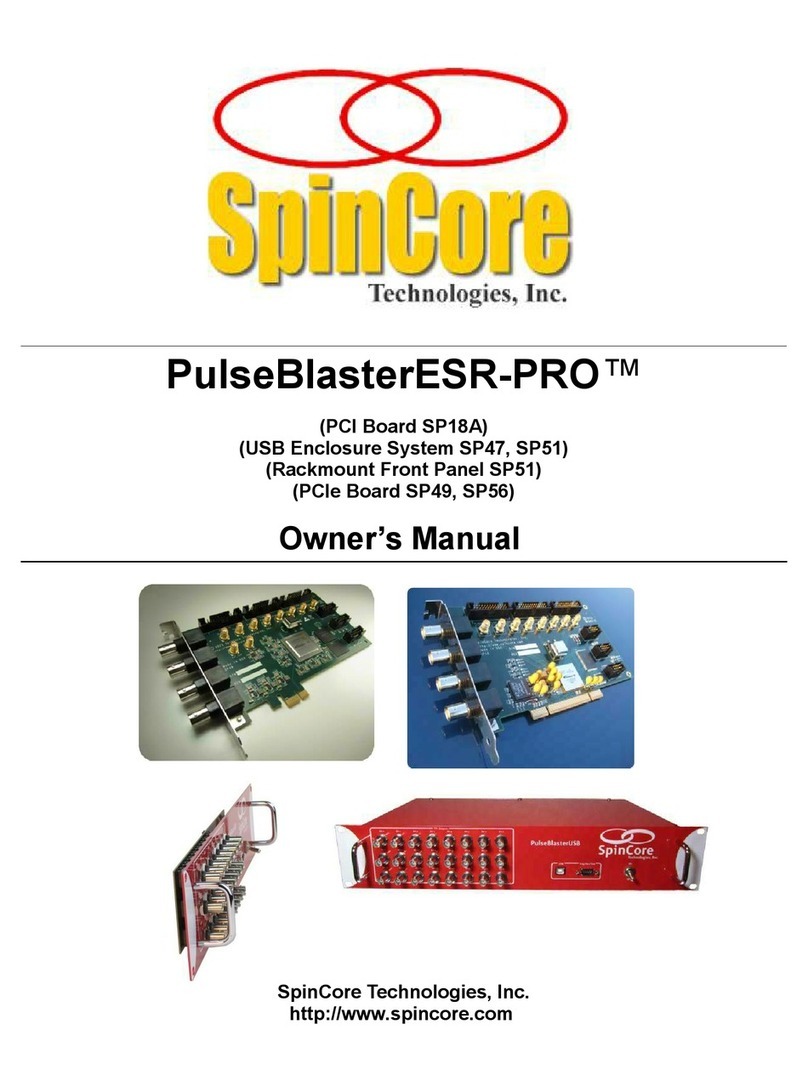
SpinCore Technologies PulseBlasterESR DualCore 8M User manual

PulseBlasterESR DualCore 8M™
Owner’s Manual
SpinCore Technologies, Inc.
http://www.spincore.com

PulseBlasterESR DualCore 8M
Congratulations and thank you for choosing a design from SpinCore
Technologies, Inc.
We appreciate our business!
At SpinCore we aim to full support the needs of our customers. If
ou are in need of assistance, please contact us and we will strive to
provide the necessar support.
© 2009-2013 SpinCore Tec nologies, Inc. All rig ts reserved.
SpinCore Tec nologies, Inc. reserves t e rig t to make c anges to t e product(s) or information erein wit out notice. PulseBlaster-
DualCore™, PulseBlaster™, SpinCore, and t e SpinCore Tec nologies, Inc. logos are trademarks of SpinCore Tec nologies, Inc. All ot er
trademarks are t e property of t eir respective owners.
SpinCore Tec nologies, Inc. makes every effort to verify t e correct operation of t e equipment. T is equipment version is not intended for
use in a system in w ic t e failure of a SpinCore device will t reaten t e safety of equipment or person(s).
www.spincore.com 2 2013/08/28

PulseBlasterESR DualCore 8M
Table of Contents
I. Introduction ............................................................................................................................... 4
Product Overview ................................................................................................................... 4
Programming Paradigm ......................................................................................................... 4
Specifications .......................................................................................................................... 5
II. Installing and Using Your PulseBlasterESR DualCore ......................................................... 6
Installation ............................................................................................................................... 6
General API Programming Information .................................................................................. 6
Triggering PulseProgram Execution ....................................................................................... 7
Stopping PulseProgram Execution ......................................................................................... 7
III. Test Programs ....................................................................................................................... 8
Example Programs ................................................................................................................. 8
Example 1 ........................................................................................................................ 8
Example 2 .......................................................................................................................... 9
Example 3 ........................................................................................................................ 10
Example 4 ......................................................................................................................... 11
Example 5 ......................................................................................................................... 12
Example 6 ......................................................................................................................... 12
IV. Appendices ......................................................................................................................... 13
Appendix A: Connectors ....................................................................................................... 13
HW_TRIG/RESET Header ............................................................................................... 13
CLOCK Header ................................................................................................................. 14
Appendix B: Hardware Triggering/Reset .............................................................................. 14
Appendix C: Sync ronization of Multiple Boards ................................................................. 15
V. Related Products and Accessories ....................................................................................... 16
VI. Contact Information ............................................................................................................. 17
VII. Document Information ....................................................................................................... 18
www.spincore.com 3 2013/08/28

PulseBlasterESR DualCore 8M
I. Introduction
Product Overview
T e SpinCore PulseBlasterESR DualCore 8M is a dual-core PulseBlaster design implemented on a new
series of PulseBlasterESR PCI boards wit up to 4194304 instruction per core. T e dual-core design uses two
of SpinCore's proprietary PulseBlaster processor cores on a single c ip. T is new design allows t e user to
program and run completely independent programs on eac core, in parallel, w ile maintaining precise timing
sync ronization between eac core.
Diagram 1 : SpinCore PulseBlasterESR DualCore Design Arc itecture
Bot cores are driven by t e same single clock source at 500 MHz. T ey are sync ronized to start at t e
same time and run unique pulse programs/sequences concurrently. At 500 MHz, t e available resolution of
eac pulse/delay/interval is 2.00 ns (one clock cycle), t e minimum pulse/delay/interval lengt is 18 clock cycles,
or 36 ns, and t e maximum pulse/delay/interval lengt is 229 clock cycles (~1.07 seconds). Eac core as 4M
(4194304) memory words available for writing pulse programs, i.e., t ere can be up to 4194304 lines in your
pulse program per core.
T e basic arc itecture of t e individual PulseBlaster processor core is described in multiple documents,
including t e manuals for PulseBlaster and PulseBlasterESR boards, available on-line at t e SpinCore's website
www.spincore.com. (Note t at t e PulseBlasterESR DualCore uses simplified PulseBlaster Cores t at allow for
'continue' and 'stop' operations only.)
Programming Paradigm
Eac core can be individually programmed wit an arbitrary sequence of intervals. Eac interval can be of
unique lengt , and up to 4M intervals can be accommodated per sequence. Since eac interval can be a pulse
or a delay, t e programming of eac core involves t e loading of two basic parameters per interval: t e output
state (logical 0 or 1), and t e duration of t e state (in nanoseconds, microseconds, milliseconds).
Eac core can be independently programmed and triggered. T e low-level interaction is accomplis ed
t roug a dedicated Application Programming Interface (API) package called t e DualCore SpinAPI, available
for download on SpinCore's website: www.spincore.com. Virtually any ig er-level application package
(Matlab, LabVIEW etc.) can interact wit t e board t roug t e provided SpinAPI functions.
www.spincore.com 4 2013/08/28
PCI Interface
SRAM
4M Words
PulseBlasterTM
Timing Core 1
Host PC
SRAM
4M Words
PulseBlasterTM
Timing Core 0
Memory Controller
Memory Controller
Clock and Triggering
Circuitry
Flag 0
Flag 1

PulseBlasterESR DualCore 8M
Specifications
Parameter Min Typ Max Units
Digital Outputs Number of Digital Outputs 2
Logical 1 Output Voltage 2.00(1) 3.3 V
Logical 0 Output Voltage 0 V
Output Drive Current 40 mA
Rise/Fall Time <1 ns
Digital Inputs
(HW_Trig, HW_Reset)
Logical 1 Input Voltage 1.7 3.3 V
Logical 0 Input Voltage -0.5 0.7 V
Pulse Program Number of Cores 1 2 > 4
Number of Instruction (per Core) 4194304 instructions
Pulse Resolution 2.00 ns
Pulse Lengt 36 ns ~1.07 s
Supported Operations CONTINUE, STOP
Table 1: Specifications of t e PulseBlasterESR DualCore Design
(1)T is value is wit a 50Ω terminating resistance.
www.spincore.com 5 2013/08/28

PulseBlasterESR DualCore 8M
II. Installing and Using Your PulseBlasterESR DualCore
Installation
To install t e board you must complete t e following t ree steps:
1) Install t e latest MultiCore SpinAPI package, available ere.
–T e DualCore PulseBlasterESR board requires a specialized version of SpinAPI called t e
MultiCore SpinAPI.
2) S ut down computer, insert t e PulseBlasterESR DualCore 8M card, and fasten t e PC bracket.
–Your system s ould detect t e board as a “PulseBlaster Multicore” device.
3) Power up and follow t e installation prompts.
Now you are ready to run t e test programs provided in t e SpinAPI package.
Note: To compile and run your own C programs, you may want to download t e SpinAPI Tools package t at
contains a pre-configured compiler; t e SpinAPI Tools package is also available for download at t e URL above.
General API Programming Information
Seven test programs (executables and t eir C source files) are available for testing. Assuming t e default
installation, t e test programs will be available on t e computer at t e following location: Start → All Programs
→ SpinAPI → Examples → DualCore Examples (t e default installation location is:
“C:\SpinCore\SpinAPI\Examples\DualCore Examples”). T e .c files can be modified and recompiled to create
custom test programs.
T e SpinAPI programming paradigm is simple:
1.Include t e “spinapi. ” in your C-file and link your executable to t e SpinAPI library.
2.Initialize t e API by calling t e function pb_init(). T is function must be called and return successfully in order
for t e API to function properly.
3.If t ere is more t an one board installed in your system, select t e correct board by calling
pb_select_board(board_number).
4.Tell t e API t e board's internal operating clock frequency. T is can be done by calling
pb_set_clock(clock_freq) wit t e appropriate internal operating frequency (500 MHz for t e PulseBlasterESR
DualCore 8M.)
5.Start programming a PulseProgram memory device. T is can be accomplis ed by calling
pb_start_programming(device). T e available devices on t e PulseBlasterESR DualCore 8M are t e
C RE0_MEM (core 0's PulseProgram memory) and C RE1_MEM (core 1's PulseProgram memory.)
6.Begin programming a PulseProgram sequence. A CONTINUE instruction can be programmed by calling
pb_inst(flag, time_ns). A STOP instruction can be programmed by calling pb_inst_stop().
Note: T e last instruction in t e PulseProgram must be a STOP instruction, or t e program will loop infinitely.
7.Stop programming t e selected device. T is can be accomplis ed by calling pb_stop_programming().
8.Select w ic cores are enabled by calling pb_core_select(core_mask). Eac bit of t e core mask corresponds
to t at core being enabled (i.e. bit 0 corresponds to core 0.)
9.Trigger t e selected cores by using pb_start(), or reset t e board wit pb_stop().
10.Close t e API by calling pb_close().
For more information on using t e DualCore SpinAPI, see t e “SpinAPI Reference Manual.pdf” found in t e
SpinAPI directory.
www.spincore.com 6 2013/08/28

PulseBlasterESR DualCore 8M
Triggering PulseProgram Execution
T e PulseBlasterESR DualCore can be triggered in two ways, eit er by software trigger or ardware trigger.
T e software trigger is initiated by sending a command from t e ost PC via t e pb_start() function. Since t e
PulseBlasterESR DualCore boards are typically used wit non real-time operating systems, t e exact time
between issuing a software trigger and t e board acting on t at trigger cannot be precisely specified. For
precision control, t e pulse program can also be triggered by setting t e HW_Trigger pin to a logical 0. T is will
cause t e pulse program to be triggered wit a latency of seven clock cycles. For more information on t e
ardware trigger, see Appendix B: Hardware Reset/Triggering.
Stopping PulseProgram Execution
T e PulseBlasterESR DualCore can be stopped by using eit er t e software or ardware reset. T e
software reset is initiated by sending a command from t e ost PC via t e pb_stop() function. Since t e
PulseBlasterESR DualCore boards are typically used wit non real-time operating systems, t e exact time
between issuing a software reset and t e board acting on t at reset cannot be precisely specified. For precision
control, t e pulse program can also be reset by setting t e HW_Reset pin to a logical 0. T is will cause t e
pulse program stop and t e program counter to reset wit in one clock cycle. For more information on t e
ardware reset, see Appendix B: Hardware Reset/Triggering.
www.spincore.com 7 2013/08/28

PulseBlasterESR DualCore 8M
III. Test Programs
Example Programs
Seven test programs ave been packaged wit t e SpinAPI driver suite to illustrate t e basic features and
functionality of t e PulseBlasterESR DualCore 8M design. All programs can be found at: Start → All Programs
→ SpinAPI → Examples → DualCore Examples (t e default installation location is:
“C:\SpinCore\SpinAPI\Examples\DualCore Examples”).
Example 1
T e first test program, pb_dualcore_example1.c demonstrates t at bot cores (c annels) can generate
identical pulses t at are precisely sync ronized.
An excerpt from t e code to program t e cores is as follows:
PulseProgram 1: Excerpt from pb_dualcore_example1.c
In Example 1, bot cores are programmed wit identical content. Later in t e program, bot cores are
triggered at t e same time using pb_start(). T e resulting output s ould be four identical 50.0 ns pulses on
BNC0 and BNC1.
NOTE: W en attac ing an oscilloscope to t e board to observe t e pulses, care s ould be taken to use
cables of t e same type and lengt for eac c annel, as skew can be induced due to propagation delays.
Conversely, any in erent variations in on-c ip propagation delays can be compensated by appropriate variations
in cable lengt .
www.spincore.com 8 2013/08/28
//********* Program Core0 ******************-/
pb_start_programming (CORE0_MEM);
pb_inst(1, 50.0 * ns);
pb_inst(0, 50.0 * ns);
pb_inst(1, 50.0 * ns);
pb_inst(0, 50.0 * ns);
pb_inst(1, 50.0 * ns);
pb_inst(0, 50.0 * ns);
pb_inst(1, 50.0 * ns);
pb_inst_stop();
instruction_count += pb_stop_programming ();
//******** Program Core1 ************************-/
pb_start_programming (CORE1_MEM);
pb_inst(1, 50.0 * ns);
pb_inst(0, 50.0 * ns);
pb_inst(1, 50.0 * ns);
pb_inst(0, 50.0 * ns);
pb_inst(1, 50.0 * ns);
pb_inst(0, 50.0 * ns);
pb_inst(1, 50.0 * ns);
pb_inst_stop();
instruction_count += pb_stop_programming ();

PulseBlasterESR DualCore 8M
Example 2
T e second example is composed of two separate files: pb_dualcore_example2a.c and
pb_dualcore_example2b.c. Eac of t ese examples are used to program one core wit a pulse sequence (50 ns
on/50 ns off) t at will occupy t e entire 4M instruction memory, and one core wit a single pulse t at is on for t e
equivalent pulse program time. T is allows for verification t at t e core's full memory is working properly and
t at t ere are no timing inaccuracies in any of t e 4M instructions.
•pb_dualcore_example2a.c : Tests core0's entire Pulse Program memory, and uses core1 to generate t e
equivalent time pulse.
•pb_dualcore_example2b.c : Tests core1's entire Pulse Program memory, and uses core0 to generate t e
equivalent time pulse.
An excerpt from t e code to program t e cores is as follows:
PulseProgram 2: Excerpt from pb_dualcore_example2a.c
Later in t e program, all bot cores are triggered at t e same time using pb_start().
NOTE: W en attac ing an oscilloscope to t e board to observe t e pulses, care s ould be taken to use
cables of t e same type and lengt for eac c annel, as skew can be induced due to propagation delays.
Conversely, any in erent variations in on-c ip propagation delays can be compensated by appropriate variations
in cable lengt .
www.spincore.com 9 2013/08/28
//********* Program Core0 ******************-/
pb_start_programming (CORE0_MEM);
i=0;
w ile(i<FULL_MEMORY_SIZE-2) {
pb_inst(1, 50.0*ns);
pb_inst(0, 50.0*ns);
i+=2;
}
pb_inst(1, 50.0*ns);
pb_inst_stop();
instruction_count_count += pb_stop_programming ();
//******** Program Core1 ******************-/
pb_start_programming (CORE1_MEM);
pb_inst(1, (FULL_MEMORY_SIZE*50.0)*ns);
pb_inst_stop();
instruction_count_count += pb_stop_programming ();

PulseBlasterESR DualCore 8M
Example 3
T e t ird test program, pb_dualcore_example3.c, demonstrates creating Pulse Programs wit an adjustable
offset between t e first pulse as low as 2.00 ns. W en t e program is run, t e user will be prompted for t e
offset between t e two cores. T is must be a multiple of 2.00 ns.
An excerpt from t e code to program t e cores is as follows:
PulseProgram 3: Excerpt from pb_dualcore_example3.c
Later in t e program, all bot cores are triggered at t e same time using pb_start(). W en t e board is
triggered, t ere s ould be two 50.0 ns pulses on BNC0 and BNC1, wit t e pulses on BNC0 starting t e
specified offset after t e pulses on BNC1.
Note t at t e offset of down to 2.00 ns is created by aving an initial instruction wit at least t e minimum
pulse lengt .
NOTE: W en attac ing an oscilloscope to t e board to observe t e pulses, care s ould be taken to use
cables of t e same type and lengt for eac c annel, as skew can be induced due to propagation delays.
Conversely, any in erent variations in on-c ip propagation delays can be compensated by appropriate variations
in cable lengt .
www.spincore.com 10 2013/08/28
//********* Program Core0 ******************-/
pb_start_programming (CORE0_MEM);
pb_inst(0, 36.0*ns + offset);
pb_inst(1, 50.0*ns);
pb_inst(0, 50.0*ns);
pb_inst(1, 50.0*ns);
pb_inst_stop();
instruction_count += pb_stop_programming ();
//********* Program Core1 ******************-/
pb_start_programming (CORE1_MEM);
pb_inst(0, 36.0*ns);
pb_inst(1, 50.0*ns);
pb_inst(0, 50.0*ns);
pb_inst(1, 50.0*ns);
pb_inst_stop();
instruction_count += pb_stop_programming ();

PulseBlasterESR DualCore 8M
Example 4
T e fourt test program, pb_dualcore_example4.c, demonstrates t e stability of t e counters in eac
PulseBlaster cores by generating an increasingly long pulse, starting at t e minimum pulse lengt and increasing
by 2.00 ns every 100 ms. T is is accomplis ed by using a continuous loop wit in t e C-program. To exit t e
program, enter CTRL-C or close t e prompt window.
An excerpt from t e code to program t e cores is as follows:
PulseProgram 4: Excerpt from pb_dualcore_example4.c
As s own above, t e increasingly long pulse is generated by reprogramming t e board memory wit a new
instruction wit an increasing pulse lengt every loop.
NOTE: W en attac ing an oscilloscope to t e board to observe t e pulses, care s ould be taken to use
cables of t e same type and lengt for eac c annel, as skew can be induced due to propagation delays.
Conversely, any in erent variations in on-c ip propagation delays can be compensated by appropriate variations
in cable lengt .
www.spincore.com 11 2013/08/28
w ile(1) {
//******** Program Core0 ************************-/
pb_start_programming (CORE0_MEM);
pb_inst(1, (36.00 + i*2.00)*ns);
pb_inst_stop();
pb_stop_programming ();
//********* Program Core1 ******************-/
pb_start_programming (CORE1_MEM);
pb_inst(1, (36.00 + i*2.00)*ns);
pb_inst_stop();
pb_stop_programming ();
i++;
pb_start();
Sleep(100);
}

PulseBlasterESR DualCore 8M
Example 5
T e fift test program, pb_dualcore_example5.c, explores a range of offsets between cores. T e program
starts wit no offset, t en increases t e offset by 2.00 ns every 100 ms up until a 236 ns offset. T e offset t en
begins decreasing by 2.00 ns every 100 ms. T is is accomplis ed by using a continuous loop wit in t e C-
program. To exit t e program, enter CTRL-C or close t e prompt window.
An excerpt from t e code to program t e cores is as follows:
PulseProgram 5: Excerpt from pb_dualcore_example5.c
NOTE: W en attac ing an oscilloscope to t e board to observe t e pulses, care s ould be taken to use
cables of t e same type and lengt for eac c annel, as skew can be induced due to propagation delays.
Conversely, any in erent variations in on-c ip propagation delays can be compensated by appropriate variations
in cable lengt .
Example 6
T e sixt example, pb_dualcore_mem_test.c, is a memory verification tool. T is program is used primarily to
test t e memory read/write speeds and verify t at t e memory is working properly. W en t e program is run, it
will write a random patterns to eac memory address, and t en read back t e result, verifying t at t e memory is
working properly and displaying t e read and write speeds t at were obtained.
If a large number of errors are occurring, it could mean t at t e memory is malfunctioning. Please note t at if
t e PulseBlaster Cores are running, t e PCI bus will not ave access to t e internal memory, and t e memory
tests will fail.
www.spincore.com 12 2013/08/28
w ile(1) {
//******** Program Core0 ************************-/
pb_start_programming (CORE0_MEM);
pb_inst(0, (36.00 + i*2.00)*ns);
pb_inst(1, 50*ns);
pb_inst_stop();
pb_stop_programming ();
//********* Program Core1 ******************-/
pb_start_programming (CORE1_MEM);
pb_inst(0, 36.00*ns);
pb_inst(1, 50*ns);
pb_inst_stop();
pb_stop_programming ();
i+= dir;
if(i==100) {
dir = -1;
}
else if(i==0) {
dir = 1;
}
pb_start();
Sleep(25);
pb_stop();
}

PulseBlasterESR DualCore 8M
IV. Appendices
Appendix A: Connectors
Note: For t e PulseBlasterESR DualCore 8M design, only flags 0 and flags 1 are used (BNC0 and BNC1
respectively.)
T e s rouded IDC connectors labeled Flag 12..23and Flag 24.. 35 can also be accessed using an
SP32 board (Figure 1) w ic allows t e use of MMCX cables. T is enables t e individual bits of t e PulseBlaster
to be more easily accessed. Pin 1 on t e MMCX adapter board can identified wit a square pin.
HW_TRIG/RESET Header
www.spincore.com 13 2013/08/28
Diagram 2: PulseBlaster DualCore Connector Layout
BNC3
BNC2
BNC1
BNC0
FLAG7_OUTFLAG6_OUTFLAG5_OUTFLAG4_OUT
EEPROM_CONFIG
STRATIX_CONFIG
HW_TRIG/RESET
Flags24...35 Out
Flags12...23 Out
BNC0
Diagram 3: HW_TRIG/RESET Header
1
1
2
3
4
5
6
7
8
9
10
CLOCK
FPGA

PulseBlasterESR DualCore 8M
Pin Number Function
1 GND
2 INT0
3 GND
4 INT1
5 GND
6 INT2
7 GND
8 HW_Reset
9 GND
10 HW_Trigger
Table 2: HW_TRIG/RESET Header Pin-out
CLOCK Header
Pin Number Function
1 No Connect
2 VCC(3.3V)
3 No Connect
4 VCC(3.3V)
5 GND
6 CLOCK_INPUT
Table 3: CLOCK Header Pin-out
Appendix B: Hardware Triggering/Reset
In order to provide precise and predictable triggering and reset latencies, t e PulseBlasterESR DualCore
provides an external ardware reset and ardware trigger inputs. T ese inputs can be found on t e
HW_TRIG/RESET eader.
www.spincore.com 14 2013/08/28
Diagram 4: CLOCK Header
1
2
3
4
5
6

PulseBlasterESR DualCore 8M
T e ardware trigger (HW_Trigger) and reset pins (HW_Reset) are pulled internally to a logical ig level via
a 10kΩ resistor. In order for a ardware trigger or reset to be detected, t e appropriate pin must be driven low
via an external source for at least one clock period (2.0 ns). Once a ardware trigger as been detected, t e
enabled PulseBlaster Cores will start executing after seven clock cycles (14.0 ns). A ardware reset as a
latency of one clock cycle. Maximum jitter for bot external ardware signals is one clock cycle (2.0 ns).
In cases w ere it is necessary to ave precise control of t e triggering and reset timings, an external
triggering source suc as a PulseBlaster24 s ould be used.
Appendix C: S nchronization of Multiple Boards
In cases w ere it is necessary to ac ieve sync ronization between multiple boards, it is possible to combine
t e use of t e ardware trigger and reset mec anisms along wit a single clock source. Diagram 5 below s ows
an example setup for ac ieving multiple board sync ronization.
In order to ensure accurate sync ronization of cores between boards, it is necessary t at t e boards be
driven from t e same clock source. T e CLOCK eader diagram in Appendix A s ows t e pin-out for t e clock
eader for providing t e clock signal to t e boards.
Once t e boards are being driven from a single clock source, an external trigger source (suc as a
PulseBlaster24) s ould be used to trigger t e boards wit precise timing. A single flag from t e PulseBlaster24
can be used to drive all of t e Hardware Triggers low in order to trigger t e boards. In order to avoid multiple
triggers being detected, t e trigger pulse cannot be longer t an t e Pulse Program.
Eac board can be can t en be programmed from t e ost PC, and t en triggered by sending a software
trigger to t e Trigger Source.
www.spincore.com 15 2013/08/28
Diagram 5: Example setup for ac ieving multiple board sync ronization
Trigger Source
(i.e. PulseBlaster24)
Multiple PulseBlasterESR DualCore Turbo
50 MHz Clock
Source
Flag Output
Software Trigger
(from ost PC)
Clock In Clock In
Clock In
Clock In
Flag utputs
Flag utputs
Flag utputs
HW_Trigger
HW_Trigger
HW_Trigger

PulseBlasterESR DualCore 8M
V. Related Products and Accessories
1. OCXO – Oven Controlled Oscillator. Figure 1 – T is oscillator is available in a frequency of 50 MHz.
For ordering information contact SpinCore at ttp://www.spincore.com/contact.s tml.
www.spincore.com 16 2013/08/28
Figure 1 CX ven Controlled scillator

PulseBlasterESR DualCore 8M
VII. Document Information
Document Title: PulseBlasterESR DualCore 8M
Document Number: DA-76
File Name: PBESR_DualCore_Manual
Revision History: Revision History Available at SpinCore
www.spincore.com 18 2013/08/28
Table of contents
Other SpinCore Technologies Computer Hardware manuals

