SpinCore Technologies PulseBlasterESR-PRO-200-cPCI User manual


PulseBlasterESR-PRO-200-cPCI
http://www.spincore.com 2 2017/01/24
© 2000-2017 SpinCore Technologies, Inc. All rights reserved.
SpinCore Technologies, Inc. reserves the right to make changes to the prod ct(s) or information herein witho t notice. P lseBlasterESR-PRO-
200-cPCI™, P lseBlaster™, SpinCore, and the SpinCore Technologies, Inc. logos are trademarks of SpinCore Technologies, Inc. All other
trademarks are the property of their respective owners.
SpinCore Technologies, Inc. makes every effort to verify the correct operation of the eq ipment. This eq ipment version is not intended for
se in a system in which the fail re of a SpinCore device will threaten the safety of eq ipment or person(s).
Congratulations and thank you for choosing a design from
SpinCore Technologies Inc.
We appreciate your business!
At SpinCore we aim to fully support the needs of our customers. If you
are in need of assistance please contact us and we will strive to provide
the necessary support.

PulseBlasterESR-PRO-200-cPCI
Table of Contents
I. Introduction ........................................................................................ 5
II. Device Description and Specifications .......................................... 6
Device Overview ................................................................................................................... 6
System Architecture ........................................................................................................ 6
Output Signals ................................................................................................................. 6
Timing Characteristics ..................................................................................................... 7
Instruction Set (Flow Control) ..................................................................................... 7
On- oard Clock ............................................................................................................... 7
Device Memory ................................................................................................................ 7
External Inputs ................................................................................................................. 7
Summary ............................................................................................................................... 8
Output Signals ................................................................................................................. 8
Timing Characteristics ..................................................................................................... 8
Instruction Set (Program Flow) ....................................................................................... 8
On- oard Clock ............................................................................................................... 8
Device Memory ................................................................................................................ 8
External Input Specifications ........................................................................................... 8
III.Installation ......................................................................................... 9
Installing the PulseBlasterESR-PRO-200-cPCI ................................................................. 9
IV. Programming PulseBlaster Devices ........................................... 10
Introduction ........................................................................................................................ 10
Programming Paradigm .................................................................................................... 10
PulseBlaster Interpreter ..................................................................................................... 11
PulseBlaster.NET ................................................................................................................ 12
MATLAB GUI ....................................................................................................................... 13
LabVIEW Extensions ......................................................................................................... 14
C/C++ Programming .......................................................................................................... 15
http://www.spincore.com 3 2017/01/24

PulseBlasterESR-PRO-200-cPCI
V. Connecting to PulseBlaster Devices ............................................ 16
Connector Information ...................................................................................................... 16
NC Header Connectors ............................................................................................... 16
IDC Headers .................................................................................................................. 17
HWTrig/Reset Header ................................................................................................... 19
VI. Related Products and Accessories ............................................ 21
VI.Contact Information ....................................................................... 22
I.Document Information ..................................................................... 22
http://www.spincore.com 4 2017/01/24

PulseBlasterESR-PRO-200-cPCI
I. Introduction
The P lseBlasterESR-PRO-200-cPCI is a programmable m ltichannel p lse/delay generator in the
CompactPCI form factor. This device is capable of generating p lses and delays with d ration ranging from 5 ns
to 2.3 x 10⁷ seconds (260 days). The P lseBlasterESR-PRO-200-cPCI feat res o tp ts on BNC connectors and
IDC headers, highly flexible program flow control, and can accommodate p lse programs containing p to 4096
instr ctions (if more instr ctions are necessary, please contact SpinCore Technologies, Inc. for more information).
The P lseBlasterESR-PRO-200-cPCI is capable of generating complex o tp t p lse seq ences feat ring
very short and very long p lses and delays in the same seq ence. P lses/delays can be as short as one clock
cycle, to as long as 252 clock cycles. Regardless of the p lse/delay length, timing resol tion is only one clock
cycle.
The intelligence of the P lseBlasterESR-PRO-200-cPCI comes from its proprietary P lseBlaster processor
core. Unlike general-p rpose processors, the P lseBlaster processor core feat res a highly optimized instr ction
set designed for timing applications. A niq e feat re of the P lseBlaster processor core is the ser can vary the
exec tion time of instr ctions.
User interaction with the P lseBlasterESR-PRO-200-cPCI can be accomplished in several different ways.
Many Graphical User Interfaces (GUI) are offered by SpinCore Technologies that allow a ser with little to no
programming experience to create, edit, save and r n p lse programs. Development environments like
LabVIEW, MATLAB, and C/C++, are s pported by sing the SpinAPI package, a dedicated Application
Programming Interface (API) package. The SpinAPI package can be sed with most Windows programming
environments and can be sed with other operating systems, incl ding Lin x. Software for the P lseBlasterESR-
PRO-200-cPCI is available on o r website: http://www.spincore.com/s pport/.
http://www.spincore.com 5 2017/01/24

PulseBlasterESR-PRO-200-cPCI
II. Device Description and Specifications
Device Overview
System Architecture
The major b ilding blocks of the P lseBlaster processor core are the SRAM memory, the microcontroller
core ( PC), the integrated b s controller (IBC), the co nter, and the o tp t b ffers. All components are
located on a single silicon chip, making the design a System-on-a-Chip (SOC). User control of the device is
provided thro gh the integrated b s controller (IBC) sing the CompactPCI b s. The fig re below shows the
block diagram of the P lseBlaster processor core.
Output Signals
P lse seq ences are o tp t digitally sing 3.3 V Low Voltage TTL (LVTTL). If the channel is on, then the
device will o tp t 3.3 V nterminated, and if the channel is off, the device will o tp t 0.0 V, nterminated.
Each channel is capable of delivering p to 25 mA per channel. If more o tp t c rrent is necessary, the
individ al channels can be driven in parallel.
O tp ts are available on BNC connectors and IDC headers. The BNC connectors are impedance
matched to 50 Ω and are located on the mo nting bracket. All o tp ts are available on IDC headers located
http://www.spincore.com 6 2017/01/24
Figure 1: Block Diagram of the P lseBlaster processor core. All the components
are placed on a single silicon chip, making the design a System-on-a-
Programmable-Chip (SOPC). The clock oscillator signal is derived from an on-chip
PLL circ it typically sing a 50 MHz on-board reference clock.
CompactPCI bus

PulseBlasterESR-PRO-200-cPCI
on the board's s rface. Stat s bits are also available on IDC headers, allowing the ser or an external device
to monitor the stat s of the P lseBlaster device. For more information abo t the connections available,
please see “V. Connecting to P lseBlaster Devices.”
Timing Characteristics
The innovative architect re of the P lseBlaster processor core allows p lses/delays to be as short as one
clock cycle (5 ns) and last p to 252 clock cycles (260 days). Regardless of the timing d ration sed, the
timing resol tion is one clock cycle. A program can have both long and short p lses/delays in the same
program, and both will be acc rate to a single clock cycle.
Instruction Set Flow Control)
The P lseBlaster devices feat res a set of commands for highly flexible program flow control. The
specialized microcontroller allows for programs to incl de branches, s bro tines, and loops p to 8 nested
levels deep. These commands allow the ser to perform repetitio s events with ease.
Instr ction exec tion time can be set by the ser. The minim m instr ction exec tion time is five clock
cycles (25 ns), and the maxim m is 252 clock cycles (260 days). To create p lses with d ration shorter than
five clock cycles, the Short P lse Feat re will need to be sed. The Short P lse Feat re allows p lse
d ration to be as short as one clock cycle (5 ns); however, at least five clock cycles are still req ired for the
P lseBlaster processor core to process the instr ction. For more information abo t P lseBlaster processor
core architect re, please see the “Instr ction Set Architect re” of Using SpinAPI in C/C++ in P lseBlaster
Programming, fo nd at: http://www.spincore.com/s pport/spinapi/ sing_spin_api_pb.shtml.
On-Board Clock
The P lseBlaster device accepts an on-board 50 MHz oscillator. The on-board oscillator's freq ency is
internally m ltiplied to 200 MHz by sing a Phase-Locked Loop (PLL). The device can be externally clocked
by removing the oscillator and attaching an eq ivalent external so rce to the oscillator mo nt. The
P lseBlaster device does not have on-board termination for the clock inp t signal. Applying less than 0.0 V or
more than 3.3 V to the clock inp t pins will damage the P lseBlaster device.
CAUTION: Incorrectly attaching an external clock source will damage the Pulse lasterESR-PRO-200-
cPCI. Contact SpinCore Technologies, Inc. if you would like information on how to use an external clock
source.
Device Memory
The memory will hold p to 4096 instr ctions. Programs do not need to fill the memory; they can be as
short as desired. If larger device memory is req ired, please contact SpinCore Technologies, Inc.
http://www.spincore.com 7 2017/01/24

PulseBlasterESR-PRO-200-cPCI
External Inputs
The P lseBlaster device has 2 external inp ts for device control: HW_Trig and HW_Reset. If HW_Trig is
activated, then the device will start r nning the program (the P lseBlaster device m st be programmed first).
If HW_Reset is activated, then the device will be stopped. The two separate lines combine the convenience
of triggering (e.g., in cardiac gating) with the safety of a "stop/reset" line. External inp ts are described f rther
in “V. Connecting to P lseBlaster Devices.”
http://www.spincore.com 8 2017/01/24

PulseBlasterESR-PRO-200-cPCI
Summary
Output Signals
4 bracket-mo nted BNC connectors, impedance matched to 50 Ω. 3.3 V LVTTL.
21 individ ally controlled digital o tp t signals on IDC headers. 3.3 V LVTTL.
25 mA o tp t c rrent per o tp t line.
4 stat s o tp ts on IDC header.
Timing Characteristics
Shortest p lse/delay: 1 clock cycle (5.0 ns).
Longest p lse/delay: 252 clock cycles (260 days).
P lse resol tion: 1 clock cycle (5.0 ns), regardless of p lse length.
Instruction Set Program Flow)
User-programmable instr ction exec tion time.
S bro tines can be nested p to 8 levels deep.
Loops can be nested p to 8 levels deep.
20-bit loop co nters (maxim m of 1,048,576 repetitions).
Branch range incl des the entire memory.
Latency after trigger (WAIT state) – 8 clock cycle latency (40 ns at 200 MHz), adj stable to 20
seconds in d ration.
External trigger and reset provide external control of the P lseBlaster device.
On-Board Clock
50 MHz on-board oscillator.
200 MHz internal clock freq ency by se of a Phase-locked Loop.
External clock so rce may be sed (contact SpinCore Technologies, Inc. for information on sing an
external clock so rce).
Device Memory
Up to 4096 instr ctions.
External Input Specifications
External triggering and reset. Tolerance: 0.0 V minim m, 3.3 V maxim m.
http://www.spincore.com 2017/01/24

PulseBlasterESR-PRO-200-cPCI
III. Installation
Installing the PulseBlasterESR-PRO-200-cPCI
To install the board yo m st ninstall any previo s versions of SpinAPI and complete the following:
1. Install the latest version of SpinAPI fo nd at: http://www.spincore.com/s pport/spinapi/.
•SpinAPI is a c stom Application Programming Interface developed by SpinCore Technologies,
Inc. for se with the P lseBlaster board. It can be tilized sing C/C++ or graphically sing the
options in the next section below. The API will also install the necessary drivers.
•There is also a package with example programs available to download.
2. Sh t down the comp ter, npl g the power cord, insert the P lseBlaster card into an available
CompactPCI comp ter b s and fasten the card sec rely in place.
3. Pl g the power cord back in, t rn on the comp ter and follow the installation prompts.
We recommend r nning example programs after yo installed the P lseBlasterESR to verify that yo r
device is f nctional. These example files can be fo nd at:
http://www.spincore.com/s pport/spinapi/spinapi_examples.shtml. Examples can be downloaded individ ally
or all at once sing the Complete SpinAPI Examples Installer.
Be s re to download either the 32-bit or 64-bit version which matches the operating system of yo r
comp ter. Save the .exe file to yo r Desktop when prompted to select a location and r n the file. The
installer will begin and ask for a location to save the example files. It is recommended to save these
examples nder “C:\SpinCore\SpinAPI\” for better organization. A new folder “examples” can be created
within SpinAPI for this p rpose. After selecting a destination folder, the installer will place the selected
example files at that location.
http://www.spincore.com 10 2017/01/24

PulseBlasterESR-PRO-200-cPCI
IV. Programming PulseBlaster Devices
Introduction
SpinCore Technologies provides several Graphical User Interfaces (GUIs) for creating/editing/saving
programs, programming P lseBlaster devices, and starting/stopping programs. The GUIs are the Pulse laster
Interpreter, Pulse laster.NET, MATLAB GUI, LabVIEW extensions, and C/C++ interface.
All SpinCore Technologies, Inc. software is available for free at o r website: http://www.spincore.com/s pport.
Programming Paradigm
The P lseBlasterESR-PRO-200-cPCI can be programmed with an arbitrary seq ence of intervals. Each
interval can be of niq e length, and p to 4096 intervals can be accommodated per seq ence. Beca se each
interval can be a p lse or a delay, each interval involves the loading of two basic parameters: the o tp t state
(logical 0 or 1), and the d ration of the state (in nanoseconds, microseconds, milliseconds).
The low-level interaction is accomplished thro gh a dedicated Application Programming Interface (API)
package called SpinAPI. SpinAPI is available for download on SpinCore Technologies' website:
http://www.spincore.com/. Virt ally any higher-level application package (Matlab, LabVIEW etc.) can interact with
the board thro gh the provided SpinAPI f nctions.
http://www.spincore.com 11 2017/01/24

PulseBlasterESR-PRO-200-cPCI
PulseBlaster Interpreter
Pulse laster Interpreter feat res large b ttons for program editing and exec tion, while sing text to inp t
instr ctions. Pulse laster Interpreter is incl ded with the SpinAPI software s ite. When the SpinAPI software
s ite is installed, a shortc t to Pulse laster Interpreter is a tomatically placed on the desktop. More information
on Pulse laster Interpreter is available at: http://www.spincore.com/s pport/SPBI/.
http://www.spincore.com 12 2017/01/24
Figure 2: Screenshot of the P lseBlaster Interpreter. The example shown
creates a p lse that toggles all o tp t bits on for 100 ms, then off for 500ms, and
repeats. P lseBlaster Interpreter is incl ded with the SpinAPI software s ite.

PulseBlasterESR-PRO-200-cPCI
PulseBlaster.NET
The Pulse laster.NET GUI feat res an easy-to- nderstand interface. Programming is no longer done in text,
b t instead presented as a simple vis al metaphor. O tp ts are set by sing check-boxes, and program flow
instr ctions are set by sing a drop-box. This GUI is ideal for sers with no programming experience.
Pulse laster.NET is capable of saving and loading files, allowing work to be saved and/or transferred to another
comp ter. Programming errors (e.g., invalid OpCode) are indicated to the ser immediately, red cing deb gging
time.
The latest version of the Pulse laster.NET and s pporting doc mentation is available on o r website at
http://www.spincore.com/s pport/net/.
http://www.spincore.com 13 2017/01/24
Figure 3: The P lseBlaster.NET interface. This interface is easy to se, feat ring b ttons, checkboxes,
dropboxes, and very little text se. This GUI is ideal for sers with no programming experience. P lse
programs can be saved, opened, and edited with ease.

PulseBlasterESR-PRO-200-cPCI
MATLAB GUI
The MATLAB GUI provides a simple yet powerf l interface for controlling P lseBlaster devices. Similar to the
Pulse laster.NET interface, o tp ts are set by sing check-boxes, program flow instr ctions are selected from a
drop-box, and instr ction d rations are typed in. The f ll instr ction set can be tilized, and m ltiple devices can
be controlled. Device selection is done by typing in the board's n mber, and device control is done by clicking
large b ttons at the top of the GUI. The MATLAB GUI is compatible with programs from Pulse laster.NET.
MATLAB is req ired for sing this GUI. The latest version of MATLAB GUI and download information can be
fo nd at: http://www.spincore.com/s pport/P lseBlasterMatlabGUI/
http://www.spincore.com 14 2017/01/24
Figure 4: The MATLAB GUI. This GUI controls o tp ts by sing checkboxes, program
flow instr ctions are performed thro gh drop boxes, and instr ction d rations are inp t by
sing text. This GUI can control m ltiple devices, and device control is done by clicking
large b ttons. Programs can be saved/loaded/edited with ease.

PulseBlasterESR-PRO-200-cPCI
LabVIEW Extensions
This GUI feat res large b ttons for programming the device and starting/stopping the p lse program. P lse
seq ence generation is done by t rning a channel on or off by left clicking on the b tton. The only text sed in
this GUI is to set the program flow instr ction (contin e, branch, etc.) and the d ration of the instr ction. This is
another GUI that is ideal for sers with no programming experience.
For sers with LabVIEW and programming experience, we've provided basic s b-VIs (Virt al Instr ments)
that add P lseBlaster interaction with yo r own LabVIEW programs, allowing sers to create a c stom interface.
LabVIEW can tilize the SpinAPI library for more f nctionality.
This GUI can be r n on the free LabVIEW 9.0 R ntime Engine. For s pporting doc mentation and download
information, please visit: http://www.spincore.com/s pport/PBLV/.
http://www.spincore.com 15 2017/01/24
Figure 5: P lseBlaster LabVIEW Extensions User
Interface. This GUI feat res very little text. This is ideal
for sers with no programming experience.

PulseBlasterESR-PRO-200-cPCI
C/C++ Programming
Programming P lseBlaster devices sing C/C++ is easier than ever. SpinCore Technologies offers a pre-
config red C/C++ compiler, and the SpinAPI library provides f nctions for programming P lseBlaster devices.
Programming sing C/C++ allows the ser to f lly tilize the device, incl ding the se of interr pt feat res.
Additionally, repetitive instr ctions may be easier to program sing C/C++ beca se yo can copy and paste lines
of code, which may be faster than performing many instr ctions sing a GUI.
SpinCore Technologies provides many example programs that demonstrate feat res of P lseBlaster devices.
Example programs are available by going to “Start>Programs>SpinCore>SpinAPI.” Inside this folder, open the
folder for yo r device (e.g., PBESR-PRO for P lseBlasterESR-PRO devices). To r n an example program,
do ble-click on the exec table file (*.exe). A P lseBlaster device m st be installed for the program to r n
properly.
An easy method of creating programs sing C/C++ is to modify an existing example program, and recompile.
To recompile, select the “Reb ild All” b tton (see the fig re below). The pre-config red compiler will create an
exec table file that will handle device programming, and will start the p lse program. Do ble click on the
exec table file (*.exe) to r n the program.
Download information and installation instr ctions are available at o r website at:
http://www.spincore.com/s pport/spinapi/. A description of SpinAPI and the incl ded C f nctions can be fo nd at:
http://www.spincore.com/s pport/spinapi/ sing_spin_api_pb.shtml
http://www.spincore.com 16 2017/01/24
Figure 6: Compiling a C program to r n P lseBlaster devices is easy! Programs can be made
q ickly by sing the available pre-config red compiler and the s pplied example programs. Open an
example program with the s pplied compiler, modify to yo r needs, then click “Reb ild All.” The
compiler will create an exec table file that will handle device programming, and starting yo r
program. The compiler is available at http://www.spincore.com/s pport/spinapi.
PulseBlasterESR-PRO-200-cPCI
V. Connecting to PulseBlaster Devices
Connector Information
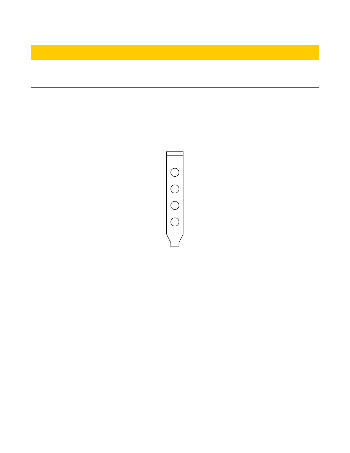
BNC Header Connectors
The fo r bracket-mo nted BNC connectors o tp ts the first fo r bits of the o tp t word (bit 0 to bit 3).
BNC 0 o tp ts bit 0, BNC 1 o tp ts bit 1, etc. The fig re below shows the location of the BNC connectors on
the mo nting-bracket.
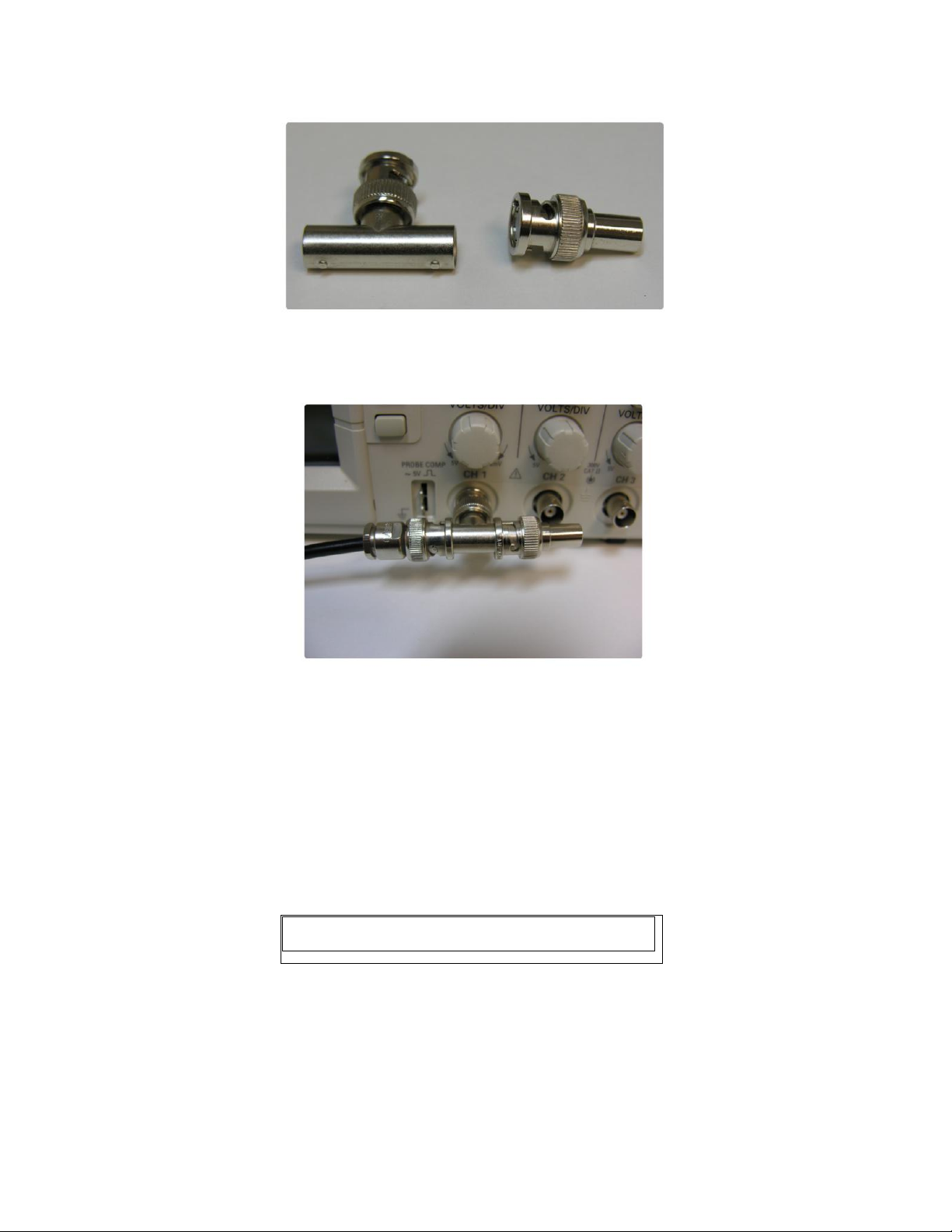
If sing a high inp t impedance oscilloscope with BNC connecters to monitor the P lseBlaster's o tp t via
the BNC connectors, place a resistor that matches the characteristic impedance of the transmission cable in
parallel with the coaxial cable at the oscilloscope inp t (e.g., a 50 Ω resistor with a 50 Ω transmission cable,
see Fig res 8 and 9 below). When sing an oscilloscope with an adj stable bandwidth, set the bandwidth to
as large as possible. Fail re to do so may yield inacc rate reado ts on the oscilloscope.
http://www.spincore.com 17 2017/01/24
Figure 7: BNC connector locations. These connectors are
located on the mo nting bracket. The BNC connectors are
impedance-matched to 50 Ω.
BNC 3
BNC 2
BNC 1
BNC 0
PulseBlasterESR-PRO-200-cPCI
IDC Headers
Three IDC headers on the P lseBlaster device provide access to all of the o tp t bits. The IDC headers
are labeled Flag0..11_O t, Flag12..23_O t and Flag24..35_O t. On each IDC header, the top row of pins
(pins 14-26) are gro nds, and the bottom row of pins (pins 1-13) are signals. The IDC header pino t is shown
in the fig re below.
Each pin of an IDC header corresponds to a bit in the O tp t Pattern and Control field of an instr ction
(Each bit corresponds to a channel). The association between bits and pins are shown in the table below.
http://www.spincore.com 18 2017/01/24
Figure 10: IDC header pino t
14 15 16 17 18 19 20 21 22 23 24 25 26
1 2 3 4 5 6 7 8 9 10 11 12 13
Figure 8: Left: BNC T-Connector and Right: BNC 50 Ohm resistor
Figure 9: BNC T-Connector on oscilloscope with coaxial transmission line connected on the left
and BNC 50 Ohm resistor connected on the right, to terminate the line.

PulseBlasterESR-PRO-200-cPCI
The P lseBlaster device feat res fo r extra o tp t signals, called "Stat s" signals, which can tell the ser
or an external device what state the P lseBlaster device is in. Pin assignments for these signals are shown in
the table above. The stat s bits are defined as follows:
• Stopped
◦ Driven high when the P lseBlaster device has enco ntered a STOP OpCode d ring program
exec tion.
• Reset
◦ Driven low when the P lseBlaster device is in a RESET state. The device m st be reprogrammed
before code exec tion can begin again.
• Running
◦ Driven high when the P lseBlaster device is exec ting a program. This pin is low when the
P lseBlaster enters either a reset or idle state.
• Waiting
◦ Driven high when the P lseBlaster device has enco ntered a WAIT OpCode. Activating a trigger
(either hardware or software) will res me operation.
http://www.spincore.com 1 2017/01/24
Pin Assignments
Pin# Flag0..11 Flag12..23 Flag24..35
1 Bit 0 Bit 12 Stopped
2 Bit 1 Bit 13 Reset
3 Bit 2 Bit 14 R nning
4 Bit 3 Bit 15 Waiting
5 Bit 4 Bit 16 Un sed
6 Bit 5 Bit 17 Un sed
7 Bit 6 Bit 18 Un sed
8 Bit 7 Bit 19 Un sed
9 Bit 8 Bit 20 Un sed
10 Bit 9 Bit 21 Un sed
11 Bit 10 Bit 22 Un sed
12 Bit 11 Bit 23 Un sed
13 Un sed Un sed Un sed
14-26 Gro nd Gro nd Gro nd
Table 1: IDC header pino t description. Every bit of
the O tp t Pattern and Control field correspond to a
channel. Pins 1 – 4 on IDC header “Flag24...35” are
stat s bits. They allow the ser or an external device
to monitor the state of the P lseBlaster device.

PulseBlasterESR-PRO-200-cPCI
HWTrig/Reset Header
This is an inp t connector for hardware triggering (HW_Trig) and hardware resetting (HW_Reset). If
HW_Trig is activated, then the device will start r nning the program (the P lseBlaster device m st be
programmed first). If HW_Reset is activated, then the device will be stopped. Pins 1 and 2 are the reset and
trigger signal pins, respectively, and pins 3 and 4 are gro nds. The header pino t is shown in the fig re
below.
CAUTION: The Pulse laster requires 3.3 V input signals. Applying voltages to the input pins that
are greater than 3.3 V or less than 0V will damage the PulseBlasterESR-PRO-200-cPCI.
The external inp ts are activated by a transition from logical high to logical low. The inp t is activated as
long as the voltage remains at logical low (e.g., if HW_Reset is held low, the device will stay in a reset state,
regardless if software or hardware triggers are sed). To activate the external inp ts, the signal pin m st be
shorted to gro nd, ca sing the transition. Both of these signals are p lled high to 3.3 V via 10k Ω resistors.
Gro nd pins are provided next to the signal pins, so activating HW_Trig and HW_Reset is as easy as
connecting the signal pin to a gro nd pin.
HW_Trigger (pin 2): When low voltage is detected (e.g., when shorting pins 2 and 4), one of two events
will happen. If the hardware trigger is activated when the program is idle beca se of a:
• WAIT OpCode, then the program will contin e to the next instr ction.
• STOP OpCode or from HW_Reset activation, then the program will restart exec tion from the beginning of
the program. If the STOP OpCode was sed, a HW_Reset or software reset needs to be applied before the
HW_Trigger.
Fig re 12 shows an example of the HW_Trigger signal.
http://www.spincore.com 20 2017/01/24
Figure 11: HWTrig/Reset Header pino t. Pin 1
and 2 are the HW_reset and HW_Trig,
respectively. These are p lled high by 10k Ω
resistors. They can be activated by gro nding the
signal pin (pin 1 or 2) with a gro nd pin (pin 3 or
4).
4 3
2 1
Table of contents
Other SpinCore Technologies Control Unit manuals

Popular Control Unit manuals by other brands

Mantech
Mantech MH-M18 quick start guide

MISUMI
MISUMI MP-VRM200 quick start guide

Keysight Technologies
Keysight Technologies M8192A user guide

ABB
ABB ACSM1-04 Series Quick installation guide

Mitsubishi Electric
Mitsubishi Electric EMU4-CNT-MB user manual

Emerson
Emerson SAPAG Installation and maintenance instructions


