GRASS VALLEY 8949MDA-CFR User manual

8949MDA-CFR/-SFR
HD MONITORING DA MODULE
Instruction Manual
SOFTWARE VERSION 1.0.X AND 2.0.X
071843401
JULY 2006

2 8949MDA-CFR and 8949MDA-SFR Instruction Manual
Contacting Grass Valley
Call Centers
Two international Contact Centers (US and France) can be reached 24 hours
a day, 7 days a week:
From the US: Call 1-800-547-8949 or (530) 478-4148
From other countries: Call +800 80 80 20 20 or +33 1 48 25 20 20
For your local Support Contact, please refer to www.thomsongrass-
valley.com/support/phone.
Grass Valley Web Site
The Web Site www.thomsongrassvalley.com offers the following:
Online User Documentation - Current versions of product catalogs,
brochures, data sheets, ordering guides, planning guides, manuals ans
release notes in .pdf format can be downloaded on www.thomson-
grassvalley.com/docs/.
FAQ Database - Solutions to problems and troubleshooting efforts can
be found our Frequency Asked Questions (FAQ) database on
www.thomsongrassvalley.com/support/ choose Troubleshooting/
FAQ
Software downloads - Software updates, drivers and patches can be
downloaded on www.thomsongrassvalley.com/support/ choose Trou-
bleshooting/FAQ and make a search.
Warranty registration - Use our convenient on-line registration on
www.thomsongrassvalley.com/ProdReg for product warranty regis-
tration.
Copyright © Grass Valley. All rights reserved.
This product may be covered by one or more U.S. and foreign patents.

8949MDA-CFR and 8949MDA-SFR Instruction Manual 3
Contents
Preface. . . . . . . . . . . . . . . . . . . . . . . . . . . . . . . . . . . . . . . . . . . . . . . . . . . . . . . . . . . . . . . . . . . . . 5
About This Manual . . . . . . . . . . . . . . . . . . . . . . . . . . . . . . . . . . . . . . . . . . . . . . . . . . . . . 5
8949MDA-CFR and 8949MDA-SFR . . . . . . . . . . . . . . . . . . . . . . . . . . . . . . . . . . . . . . 7
Introduction . . . . . . . . . . . . . . . . . . . . . . . . . . . . . . . . . . . . . . . . . . . . . . . . . . . . . . . . . . . 7
Features . . . . . . . . . . . . . . . . . . . . . . . . . . . . . . . . . . . . . . . . . . . . . . . . . . . . . . . . . . . . . 7
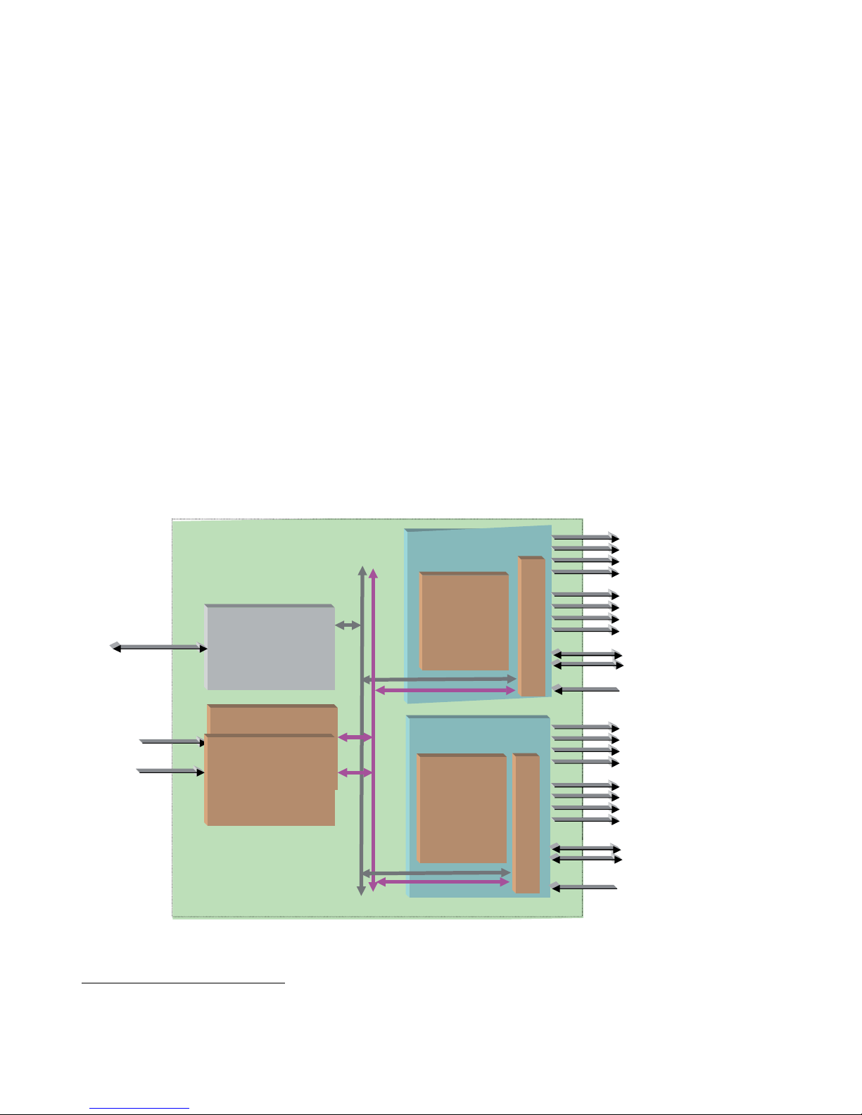
Product Architecture. . . . . . . . . . . . . . . . . . . . . . . . . . . . . . . . . . . . . . . . . . . . . . . . . . 8
Product Environment . . . . . . . . . . . . . . . . . . . . . . . . . . . . . . . . . . . . . . . . . . . . . . . . . 9
Software Version Requirement . . . . . . . . . . . . . . . . . . . . . . . . . . . . . . . . . . . . . . . . . 9
Installation . . . . . . . . . . . . . . . . . . . . . . . . . . . . . . . . . . . . . . . . . . . . . . . . . . . . . . . . . . . 10
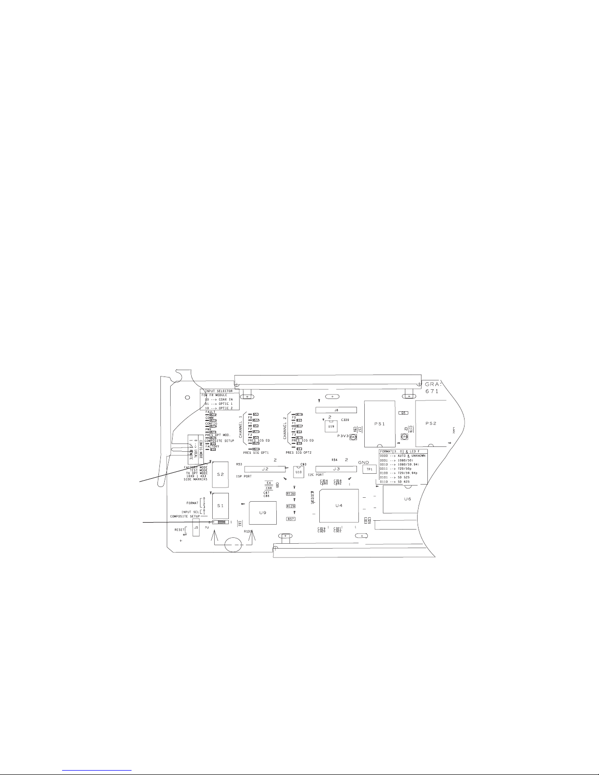
Local Configuration . . . . . . . . . . . . . . . . . . . . . . . . . . . . . . . . . . . . . . . . . . . . . . . . . 10
Module Placement in the GeckoFlex Frame . . . . . . . . . . . . . . . . . . . . . . . . . . . . . 11
Rear Module Installation . . . . . . . . . . . . . . . . . . . . . . . . . . . . . . . . . . . . . . . . . . . 11
Front Module Installation. . . . . . . . . . . . . . . . . . . . . . . . . . . . . . . . . . . . . . . . . . . 12
Optional Fiber Optic Submodule. . . . . . . . . . . . . . . . . . . . . . . . . . . . . . . . . . . . . 12
Cabling . . . . . . . . . . . . . . . . . . . . . . . . . . . . . . . . . . . . . . . . . . . . . . . . . . . . . . . . . . . . . . 14
Power Up . . . . . . . . . . . . . . . . . . . . . . . . . . . . . . . . . . . . . . . . . . . . . . . . . . . . . . . . . . . . 16
Operation Indicator LEDs . . . . . . . . . . . . . . . . . . . . . . . . . . . . . . . . . . . . . . . . . . . . 16
Remote Configuration . . . . . . . . . . . . . . . . . . . . . . . . . . . . . . . . . . . . . . . . . . . . . . . . . 18
8900NET Module Information. . . . . . . . . . . . . . . . . . . . . . . . . . . . . . . . . . . . . . . . . 18
Newton Control Panel Configuration . . . . . . . . . . . . . . . . . . . . . . . . . . . . . . . . . . 18
Web Browser Interface . . . . . . . . . . . . . . . . . . . . . . . . . . . . . . . . . . . . . . . . . . . . . . . 19
8949MDA-CFR and 8949MDA-SFR Links and Web Pages. . . . . . . . . . . . . . . . . 21
Status Web Page. . . . . . . . . . . . . . . . . . . . . . . . . . . . . . . . . . . . . . . . . . . . . . . . . . . 21
Settings Web Page . . . . . . . . . . . . . . . . . . . . . . . . . . . . . . . . . . . . . . . . . . . . . . . . . 23
Slot Config Web Page . . . . . . . . . . . . . . . . . . . . . . . . . . . . . . . . . . . . . . . . . . . . . . 25
Specifications . . . . . . . . . . . . . . . . . . . . . . . . . . . . . . . . . . . . . . . . . . . . . . . . . . . . . . . . . 27
Service. . . . . . . . . . . . . . . . . . . . . . . . . . . . . . . . . . . . . . . . . . . . . . . . . . . . . . . . . . . . . . . 29
Power-up Diagnostics Failure . . . . . . . . . . . . . . . . . . . . . . . . . . . . . . . . . . . . . . . . . 29
Troubleshooting. . . . . . . . . . . . . . . . . . . . . . . . . . . . . . . . . . . . . . . . . . . . . . . . . . . . . 29
The Electronic Circuit Breaker . . . . . . . . . . . . . . . . . . . . . . . . . . . . . . . . . . . . . . . 29
Table of Alarms . . . . . . . . . . . . . . . . . . . . . . . . . . . . . . . . . . . . . . . . . . . . . . . . . . . 30
Module Repair . . . . . . . . . . . . . . . . . . . . . . . . . . . . . . . . . . . . . . . . . . . . . . . . . . . . . . 30
Functional Description . . . . . . . . . . . . . . . . . . . . . . . . . . . . . . . . . . . . . . . . . . . . . . . . . 31
Input Processing . . . . . . . . . . . . . . . . . . . . . . . . . . . . . . . . . . . . . . . . . . . . . . . . . . . . 31
Reclocking Processing. . . . . . . . . . . . . . . . . . . . . . . . . . . . . . . . . . . . . . . . . . . . . . . . 31
HD to SD Downscaling. . . . . . . . . . . . . . . . . . . . . . . . . . . . . . . . . . . . . . . . . . . . . . . 31
Output Processing . . . . . . . . . . . . . . . . . . . . . . . . . . . . . . . . . . . . . . . . . . . . . . . . . . . 32
Microprocessor. . . . . . . . . . . . . . . . . . . . . . . . . . . . . . . . . . . . . . . . . . . . . . . . . . . . . . 32
Power Supply. . . . . . . . . . . . . . . . . . . . . . . . . . . . . . . . . . . . . . . . . . . . . . . . . . . . . . . 32
Index . . . . . . . . . . . . . . . . . . . . . . . . . . . . . . . . . . . . . . . . . . . . . . . . . . . . . . . . . . . . . . . . . . . . . . 33

4 8949MDA-CFR and 8949MDA-SFR Instruction Manual
Contents

8949MDA-CFR and 8949MDA-SFR Instruction Manual 5
Preface
About This Manual
This manual describes the features of 8949MDA-CFR and 8949MDA-SFR front
modules, their corresponding rear module (8900WFR-R), the optical submodules
1310NM-DRL (Dual Receiver Fiber Optic), 1310NM-DTL (Dual Transmitter
Fiber Optic) and 1310NM-TRL (Transceiver Fiber Optic) in the GeckoFlex frame.
As part of this module family, it is subject to Safety and Regulatory Compliance
described in the GeckoFlex frame documentation.

6 8949MDA-CFR and 8949MDA-SFR Instruction Manual
Preface

8949MDA-CFR and 8949MDA-SFR Instruction Manual 7
8949MDA-CFR and
8949MDA-SFR
Introduction
The 8949MDA-CFR or 8949MDA-SFR performs HD/SD equalization, and
reclocking for distribution of HD/SD signals among electrical connectors and/or a
fiber optic submodule and downscaling of HD video signals to SD video signals
for monitoring applications among electrical connectors.
The two models, 8949MDA-CFR (composite downscaler outputs) and
8949MDA-SFR (serial data interface downscaler outputs) must be installed in a
GeckoFlex frame.
Features
The 8949MDA module features include:
• Multi-format HD or SD on one electrical input or optical inputs,
• In HD mode for inputs:
• Up to four reclocked HD electrical outputs and up to two reclocked HD
optical outputs,
• Up to four downscaled HD to SD (SDI signals in the case of
8949MDA-SFR or composite signals in the case of 8949MDA-CFR) elec-
trical outputs,
• In SD mode for inputs:
• Up to eight reclocked SD (SDI standard) electrical outputs and up to two
reclocked SD optical outputs in the case of 8949MDA-SFR,
• Up to four reclocked SDI outputs and up to two reclocked SD optical
outputs and up to four composite outputs in the case of 8949MDA-CFR,
• Auto cable equalization for up to 330m of cable in the case of SD signals and
for up to 125m of cable in the case of HD signals,
• A range of standard definition or high definition input signal on one electrical
input or optical inputs,
• Downscaled signals with monitoring quality,

8 8949MDA-CFR and 8949MDA-SFR Instruction Manual
Introduction
• Alarm (signal presence detection) and status management,
• SNMP MIB reporting basic board alarms,
• A fiber optic submodule option providing optical input/output interfaces for all
models. One of the three different types of single-mode fiber optic submodules
can be used:
• 1310NM-DRL1- provides two optical inputs (RX1 and RX2),
• 1310NM-DTL - provides two optical outputs (TX1 and TX2),
• 1310NM-TRL - provides one optical input (RX1) and one optical output
(TX1), and
• Remote control and monitoring support: web pages, Newton control panel,
NetConfig management system.
Product Architecture
The 8949MDA-CFR and 8949MDA-SFR can only be installed in the GeckoFlex
frame illustrated in Figure 1 below.
Figure 1. Product Architecture
1. Please contact your Grass Valley representative for ordering this option (1310NM-DRL)
Frame
Bus
GeckoFlexhousing
(8900FFN)
Ethernet
8900NET
Network Interface Module
Power Supply
Power Supply
(8900F-PSX)
100 - 240 Volts
±12V
Reclocked
SD/HD
on electrical outputs
SD/HD
Gecko HD DA
(8949MDA-CFR)
Front Module
8
9
0
0
W
F
R
-
R
Front Module
8
9
0
0
W
F
R
-
R
Gecko HD DA
(8949MDA-SFR)
SD/HD
Reclocked
SD/HD
on electrical outputs
Reclocked SD/HD on
Fiber Optic Submodule
s
Composite downscaled
signals on electrical
outputs
SDI downscaled signals
on electrical outputs
8434-01
Reclocked SD/HD on
Fiber Optic Submodules

8949MDA-CFR and 8949MDA-SFR Instruction Manual 9
Introduction
Product Environment
The 8949MDA-CFR and 8949MDA-SFR modules can only be installed in a Geck-
oFlex frame (8900FF, 8900FX and 8900FFN). The devices can be located in
broadcast centers, video production facilities, OB vans and production trucks. The
main application of those products is the jitter reduction, the distribution of the
incoming SD or HD signals to the video processing devices (routers, switchers,
tape recorder, monitoring devices, etc.) and the downscaling of HD video signals
to SD or composite video signals for monitoring applications.
Software Version Requirement
This manual covers two software versions. It is important to distinguish the board
version (hardware implementation) related to the software version.
Note The part number is given on the Status web page if the 8900NET module is
present. And it is written on the module.
Table 1. Hardware/Software Compatibility
Model Board Part Number
from 1.0.6 Version
Board Part Number
from 2.0.2 Version
Board Part Number
from 2.0.4 Version
8949MDA-CFR 671-6708-10 671-6708-11 771-0283-10
8949MDA-SFR 671-6708-20 671-6708-21 771-0283-20

10 8949MDA-CFR and 8949MDA-SFR Instruction Manual
Installation
Installation
The front and the rear modules (Cabling on page 14) are delivered together as a set.
The 8949MDA-CFR and 8949MDA-SFR front modules can be plugged in and
removed from a GeckoFlex frame with power on, without disrupting operation on
adjacent running modules. When power is applied to the module, LED indicators
reflect the initialization process (see Power Up on page 16).
CAUTION It is advised to take precautions for the installation and the removal
of the optional fiber optic submodule, see Optional Fiber Optic Sub-
module on page 12.
Local Configuration
Local configuration of the 8949MDA-CFR and 8949MDA-SFR consists of several
switches (S1 and S2 blocks) as shown in Figure 2.
If you do not have an 8900NET module, you will need to configure the module
using the local onboard controls before installing the front module.
Figure 2. Switches on 8949MDA Module
Config mode
Switch position
8434-02

8949MDA-CFR and 8949MDA-SFR Instruction Manual 11
Installation
Table 2 gives the parameter to be set with the onboard switches of the 8949MDA
modules.
Module Placement in the GeckoFlex Frame
There are ten rear and front slot locations in the 2 RU frame to accommodate either
analog or digital modules. The 8949MDA-CFR or 8949MDA-SFR module can be
plugged into any one of the GeckoFlex frame slots.
Note As the module can be changed when the GeckoFlex is powered on,
before removing the cover, please put an anti-static bracelet tied to a
metal part of the frame.
Rear Module Installation
Note Never completely remove the screws which maintain the retainer strips.
To install a rear module into the frame, follow these steps:
1. Unscrew the blank rear adapter cover without removing the screws, see
Figure 3.
2. Remove the two retainer strips and the blank rear adapter cover using a
needlenose plier.
Table 2. Switch S1 and S2 Positions
Position 0 1
CONFIG MODE Local mode: the other switchesmust
be manually positioned
Remote mode: the other parameters
wil be positioned by the web pages
via the NetConfig application
FACTORY MODE OFF For maintenance only
TEST MODE OFF For maintenance only
TX OPT MODE OFF ON (enablesthe transmission through
the fiber opticsubmodule)
16X9 I 4X3 UNUSED
SIDE MARKERS UNUSED
FORMAT Selection of the incoming format:
0000 = AUTO
0001 = 1080I/50
0010 = 1080I/59.94
0011 = 720p/50
0100 = 720p/59.94
0101 = 480i/59.94
0110 = 576i/50
INPUT SEL
coax in
optic1
optic2
Selection of the input connectors:
00
01
10
COMPOSITE SETUP OFF ON

12 8949MDA-CFR and 8949MDA-SFR Instruction Manual
Installation
3. Insert the corresponding rear module in the slot.
4. Replace both retainer strips on each side of the rear module and tighten the
screws to secure the rear module.
Figure 3. Back Panel
Note To extract the rear module, do not forget to extract the front module first.
Front Module Installation
Note Before installing the front module, the rear module must be already placed.
Please refer to the Optional Fiber Optic Submodule below, if the fiber optic
submodule is present.
After installing the rear module:
1. Unscrew and remove the front cover.
2. Insert the front module in the guides of the corresponding slot.
3. The module ejector tab (Figure 4) must be locked in its locking pin.
Figure 4. Module Ejector Tab Locking Pin
Optional Fiber Optic Submodule
When the fiber optic submodule is present, it is advised to take some precautions
so as not damage the modules.
8434-03
8434 -04
Ejector
Tab
Locking Pin

8949MDA-CFR and 8949MDA-SFR Instruction Manual 13
Installation
To install the fiber optic submodule:
1. Install the rear module, refer to Rear Module Installation on page 11.
2. Install the front module, refer to Front Module Installation on page 12.
3. Slide the fiber optic submodule into the cage connector (the label on the right).
Figure 5. Fiber Optic Submodule
4. Before inserting the fiber cable, it is important to clean it with alcohol and a
lint-free filter paper.
The fiber optic submodule is hot-pluggable and may be installed or removed with
power applied to the front module.
The module type is identified by name on the label or can be identified by the direc-
tion of the two arrow indicators on the label.
Note When installed properly, the front end of the submodule will line up with the
BNCs. Do not try to force it in further.
To extract the fiber optic submodule follow the steps:
Note The fiber cable and the fiber optic submodule must be extracted before the
front and the rear modules.
1. Remove the fiber cable first.
FIBER
J7
J9
J8
8434_05
Label
Handle
Arrow Indicators:
1310-DRL
1310-DTL
1310-TRL
Fiber 2
Fiber 1

14 8949MDA-CFR and 8949MDA-SFR Instruction Manual
Cabling
2. Unlock the module by flipping the handle to the left.
3. Remove the fiber optic submodule by using its handle.
Cabling
Cabling to the 8949MDA-CFR or 8949MDA-SFR module is done on the BNCs
and the fiber connector on the rear module. Refer to Figure 5 on page 13 for the
fiber optic cabling and Figure 6 on page 15 for a detailed illustration of the rear
connections referenced below. Cabling of the rear module depends on what fiber
optic submodule option is installed as below:
• 8949MDA-CFR/-SFR without fiber optic submodule option (electrical only),
• 8949MDA-CFR/-SFR with 1310NM-DRL (Dual Receiver Fiber Optic)
• 8949MDA-CFR/-SFR with 1310NM-DTL (Dual Transmitter Fiber Optic),
and
• 8949MDA-CFR/-SFR with 1310NM-TRL (Transceiver Fiber Optic).
The 8949MDA-CFR or 8949MDA-SFR will accept any of the video standards
listed in the input specifications in Table 6 on page 27.
Connect a video input to BNC J9 or Fiber.
The 8949MDA-CFR or 8949MDA-SFR outputs conform to the video standards
listed in the output specifications in Table 6 on page 27.
Table 3 below and Table 4 on page 15 gives the inputs and the possible video
output connections for the 8949MDA modules in Figure 5 on page 13.
Table 3. Cabling Inputs and Outputs for 8949MDA-SFR Module
Fiber Optic Submodule Inputs in HD Outputs
Dual receiver J9
or Fiber 1
or Fiber 2
J1, J3, J5, J7: 4 HD-SDI outputs
J2, J4, J6, J8: 4 downscaled SD-SDI
outputs
Dual transmitter J9 J1, J3, J5, J7: 4 HD electrical outputs
Fiber 1 and Fiber 2: 2 optical HD outputs
J2, J4, J6, J8: 4 downscaled SD-SDI
outputs
Transceiver J9
or Fiber 1
J1, J3, J5, J7: 4 HD electrical outputs
Fiber 2: 1 optical HD outputs
J2, J4, J6, J8: 4 downscaled SD-SDI
outputs

8949MDA-CFR and 8949MDA-SFR Instruction Manual 15
Cabling
Figure 6. 8949MDA rear Module
Table 4. Cabling Inputs and Outputs for 8949MDA-CFR Module
Fiber Optic Submodule Inputs in HD Outputs
Dual receiver J9
or Fiber 1
or Fiber 2
J1, J3, J5, J7: 4 HD-SDI outputs
J2, J4, J6, J8: 4 downscaled composite
video outputs
Dual transmitter J9 J1, J3, J5, J7: 4 HD electrical outputs
Fiber 1 and Fiber 2: 2 optical HD outputs
J2, J4, J6, J8: 4 downscaled composite
video outputs
Transceiver J9
or Fiber 1
J1, J3, J5, J7: 4 HD electrical outputs
Fiber 2: 1 optical HD outputs
J2, J4, J6, J8: 4 downscaled composite
video outputs
8435-07
8900WFR-R
J1 J2
8434-06
Fiber 1
Fiber 2

16 8949MDA-CFR and 8949MDA-SFR Instruction Manual
Power Up
Power Up
The on-board LED indicators are illustrated in Figure 7. Upon power-up, the green
PWR LED should light and the CONFIG, FAULT and COMM LEDs should illu-
minate during the module initialization.
Note When a module is first plugged into a GeckoFlex frame, the 8900NET module
(if present) may report a momentary fault. This will clear once the module has
booted up.
Operation Indicator LEDs
With a valid input signal connected, PRES SIG LED (EQ in channel 1, OPT1,
OPT2) should be on. Refer to Table 5 on page 17 to see a complete list of possible
operating conditions and the resulting indicator status.
Figure 7. LEDs Significations - Part of the 8949MDA-CFR or 8949MDA-SFR module
Note The channel 2 LEDs are not connected.

8949MDA-CFR and 8949MDA-SFR Instruction Manual 17
Power Up
A red FAULT LED indicates an error situation and, when noted with the other indi-
cator LEDs, can indicate a specific problem area. Table 5 describes signal output
and LED indications for the various input/reference combinations.
Table 5. LED Indicators
LED Indication Condition
FAULT (red) Off Normal operation
On continuously Module hasdetected internal fault
COMM (yellow)
Off No activity on frame communication bus
Long flashLocation Command received by the module from a remote control system
Short flashActivity present on the frame communication bus
CONFIG (yellow) Off Module isin normal operating mode
On continuously Module isinitializing, changing operating modesor updating firmware
PWR (green) Off No power to module or module’sDC/DC converter failed
On continuously Normal operation, module ispowered
PRES OPT MOD
(yellow)
Off Fiber opticsubmodule not installed
On Fiber opticsubmodule installed
COMPOSITE SETUP
(yellow)
Off Setup disabled
On Setup enabled
FACTORY
(yellow)
Off Normal operation
On Test mode or factory mode
MONITORING MODE
(Channel 1
F0, F1, F2 and F3)
(yellow)
0000 --> Auto
0001 --> 1080i/50
0010 --> 1080i/59.94
0011 --> 720p/50
0100 --> 720p/59.94
0101 --> 480i/59.94
0110 --> 576i/50
PRES SIG EQ
(green)
Off No presence of signal on BNC (on J9 connector)
On continuously Presence of signal on BNC (on J9 connector)
PRES SIG OPT 1
(green)
Off No presence of optical signal on opt 1
On continuously Presence of optical signal on opt1
PRES SIG OPT 2
(green)
Off No presence of optical signal on opt 2
On continuously Presence of optical signal on opt 2

18 8949MDA-CFR and 8949MDA-SFR Instruction Manual
Remote Configuration
The 8949MDA-CFR/8949MDA-SFR configuration and monitoring can be also
performed using a web browser GUI interface or a networked Newton Control
Panel when the 8900NET Network Interface module is present in the GeckoFlex
frame (8900FFN). Each of these interfaces is described below.
8900NET Module Information
Refer to the 8900NET Network Interface Module Instruction Manual from 4.0
version for information on the 8900NET Network Interface Module and setting up
and operating the GeckoFlex 8900 frame network.
Note Upgrade software and instructions for the 8900NET can be downloaded from
the Grass Valley web site.
Newton Control Panel Configuration
A Newton Control Panel (hard or soft version) can be interfaced to the GeckoFlex
frame over the local network. Refer to the documentation that accompanies the
Newton Modular Control System for installation, configuration, and operation
information.
Control panel access offers the following considerations for module configuration
and monitoring:
• Ability to separate system level tasks from operation ones, minimizing the
potential for on-air mistakes.
• Ability to group modular products—regardless of their physical loca-
tions—into logical groups (channels) that you can easily manipulate with
user-configured knobs.
• Update software for applicable modules and assign frame and panel IP
addresses with the NetConfig Networking application.
• Recommended for real-time control of module configuration parameters, pro-
viding the fastest response time.
Note Not all module functions are available with the control panel, such as factory
default recalls.

8949MDA-CFR and 8949MDA-SFR Instruction Manual 19
Remote Configuration
An example of the Newton Configurator is shown in Figure 8.
Figure 8. Newton Configurator Example
Web Browser Interface
The web browser interface provides a graphical representation of module configu-
ration and monitoring.
Use of the web interface offers the following considerations:
• Web access will require some normal network time delays for processing of
information.
• Configuration parameter changes may require pressing Apply button or Enter,
upload processing time, and a manual screen refresh to become effective.
• Web interface recommended for setting up module signal and slot names, and
reporting status for SNMP and monitoring.
Refer to the Status web page shown in Figure 9 on page 20. The 8900 modules can
be addressed by clicking either on a specific module icon in the frame status
display or on a module name or slot number in the link list on the left.

20 8949MDA-CFR and 8949MDA-SFR Instruction Manual
Remote Configuration
In general, graphics and text colors used indicate the following:
• Green = Pass – signal or reference present, no problems detected.
• Red = Fault – fault condition.
• Yellow = Warning – signal is absent, has errors, or is mis-configured.
• Gray = Not monitored.
• White = Not present.
Note The physical appearance of the graphics on the web pages shown in this
manual represent the use of a particular platform, browser and version of
8900NET module software. They are provided for reference only. Web pages
will differ depending on the type of platform and browser you are using and
the version of the 8900NET software installed in your system. The GeckoFlex
frames works with 8900NET module from 4.0 version.
• For information on status and fault monitoring and reporting shown on the
Status page, refer to Status Web Page on page 21.
Figure 9. Main Menu
The link section lists the frame and its current modules. The selected link’s Status page is first displayed and the
sub-list of links for the selection is opened. The sub-list allows you to select a particular information page for the
selected device. Content display section displays the information page for the selected frame or module
(frame slot icons are also active links).
Refresh button for manual update of page
This manual suits for next models
2
Table of contents
Other GRASS VALLEY Control Unit manuals

GRASS VALLEY
GRASS VALLEY 8964DEC - User manual

GRASS VALLEY
GRASS VALLEY KAMELEON Series User manual

GRASS VALLEY
GRASS VALLEY 8990ARC - User manual

GRASS VALLEY
GRASS VALLEY HCO-3931 User manual

GRASS VALLEY
GRASS VALLEY KAMELEON Series User manual

GRASS VALLEY
GRASS VALLEY XCU User manual

GRASS VALLEY
GRASS VALLEY KAMELEON Series User manual

GRASS VALLEY
GRASS VALLEY KAMELEON Series User manual

GRASS VALLEY
GRASS VALLEY KAMELEON Series User manual

GRASS VALLEY
GRASS VALLEY KAMELEON Series User manual