SpinCore Technologies PulseBlaster128 User manual

PulseBlaster128
Owner's Manual
SpinCore Technologies, Inc.
www.spincore.com

PulseBlaster128
Congratulations an thank you for choosing a esign from
SpinCore Technologies, Inc.
We appreciate your business!
At SpinCore we aim to fully support the nee s of our customers. If
you are in nee of assistance, please contact us an we will strive to
provi e the necessary support.
© 2011 SpinCore Technologies, Inc. All rights reserved.
SpinCore Technologies, Inc. reserves the right to make changes to the product(s or information herein without notice.
PulseBlaster™, SpinCore, and the SpinCore Technologies, Inc. logos are trademarks of SpinCore Technologies, Inc. All other
trademarks are the property of their respective owners.
SpinCore Technologies, Inc. makes every effort to verify the correct operation of the equipment. This equipment version is not
intended for use in a system in which the failure of a SpinCore device will threaten the safety of equipment or person(s .
www.spincore.com 2 2011-08-02

PulseBlaster128
Table of Contents
I. Intro uction .............................................................................................. 4
Boar Overview ........................................................................................................... 4
Boar Layout ................................................................................................................ 5
Boar Setup ................................................................................................................. 6
How to Assemble the PB128 .................................................................................... 6
How to Connect the PB128 ....................................................................................... 6
Boar Features ............................................................................................................ 7
External Clock and Clock Output ..............................................................................
Output Signals ...........................................................................................................
Hardware Trigger and Reset .....................................................................................
PulseBlaster Address ................................................................................................
Instruction Capabilities ..............................................................................................
Pinouts .......................................................................................................................... 8
Control Header .......................................................................................................... 8
Output Headers ......................................................................................................... 9
II. Boar Functionality .............................................................................. 10
PulseBlaster Core ...................................................................................................... 10
Interrupts .................................................................................................................... 10
Overview ................................................................................................................. 10
Controlling Interrupts with Software ........................................................................ 10
Interrupt Addresses ................................................................................................. 10
Instructions ................................................................................................................ 11
Instruction Structure ................................................................................................ 11
Programming Instructions to the PB128 ................................................................. 11
www.spincore.com 3 2011-08-02

PulseBlaster128
I. Intro uction
Boar Overview
The PulseBlaster128 is a modified PulseBlaster design with 128 output pins and custom interrupt
functionality. It is built using the TerASIC DE3-150 platform. The architecture of the PulseBlaster
processor is described in detail in multiple documents including the manual of the PulseBlaster24 board
which can be found at http://www.spincore.com/CD/PulseBlaster/ PCI/ PB24/PB_Manual.pdf . In this guide
you will learn the basics to getting started with your PB128 board.
Figure 1: The PulseBlaster128
www.spincore.com 4 2011-08-02

PulseBlaster128
Boar Layout
The PB128 requires three main connections in order to function: power, USB, and clock
connections. The board comes with its own AC/DC power supply and custom power adapter to connect
to the board. In addition there is also a power switch that activates the power supply and turns the board
on. The PB128 connects to the host PC through the mini USB connector on the top edge of the board.
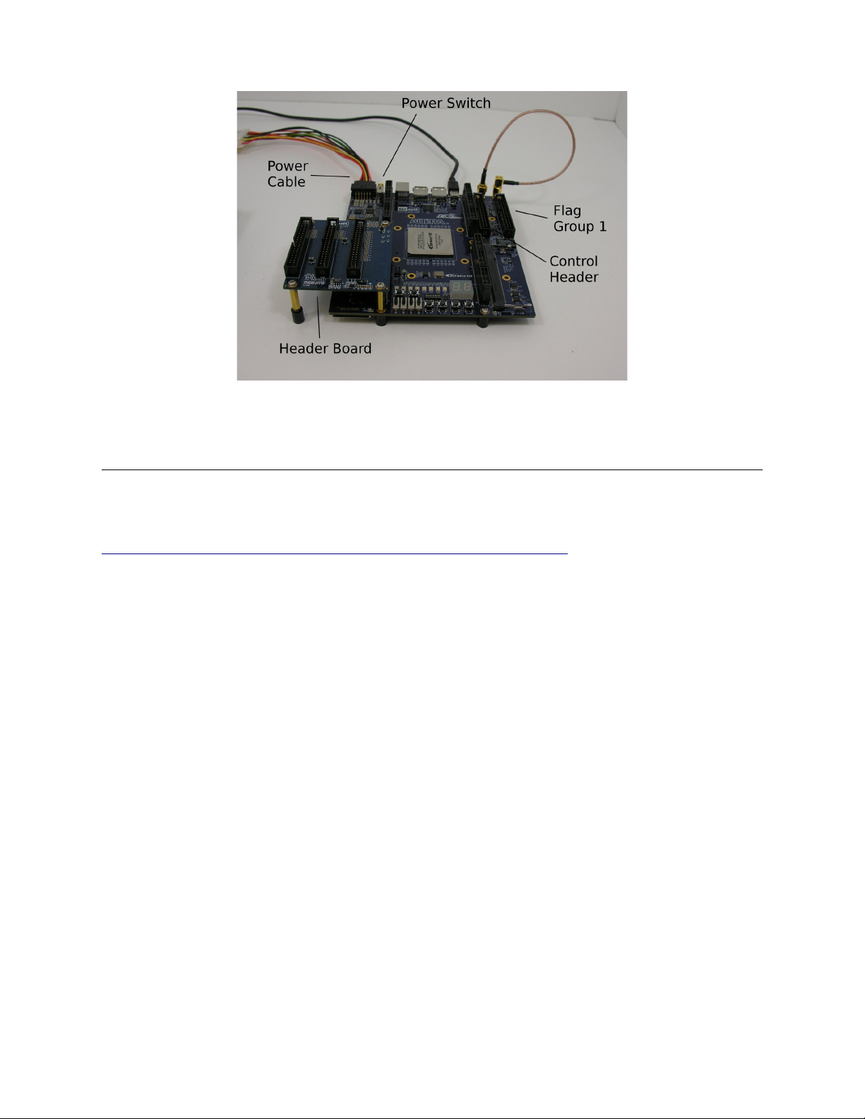
The PB128 has five headers on the board: four output headers and one control header. The 128
output channels are divided among four output headers with 32 output channels each. The board's
control signals are found on the control header. This includes signals such as the status outputs, the
hardware trigger and reset, and the hardware interrupt pins. Detailed pinouts for these headers can be
found in the Pinouts section of this guide.
The two figures below label a few important parts of the PB128.
Figure 2: Important parts of the PB128
www.spincore.com 5 2011-08-02
PulseBlaster128
Figure 3: Additional important parts of the PB128
Boar Setup
Install the Software
Install the PulseBlaster128 software package from
http://www.spincore.com/CD/PulseBlaster128/PulseBlaster128Installer.exe. Run this installer before
connecting the device.
Assemble the PB128
Remove the PB128 from its packaging and connect the Header Board to the Main Board using
the supplied screws. Make sure to connect it as shown in Figures 2 and 3. After the Header Board is
connected, it is time to add the standoffs to the bottom of the board. Put the 6 standoffs as shown in
Figure 2. Next, attach the provided SMA-to-SMA clock loop cable as shown in Figures 2 and 3; the board
will not operate without this clock cable.
Connect the PB128
After the software package has been installed, attach the PB128 to the provided power supply,
and then plug the power supply into the wall. Next attach the small end of the mini-USB cable to the
board and the large end into the PC.
Push in the power switch to power up the board. Shortly afterward, the PC will notice the device
and ask to install drivers. Install the drivers manually by specifying the location of the provided drivers
(assuming a default software installation, this will be C:\SpinCore\PulseBlaster128\drivers .
Test the Connection
Once the drivers for the device have been installed, navigate from the Windows Start Menu to
Programs → SpinCore → PulseBlaster128. Click on the link to the pb128usb_ex1.exe example program.
The program should demonstrate a simple method for switching between interrupt routines. If the board
is unconnected, the program will report “ERROR - USB device not initialized.” If this occurs, confirm that
the steps above have been completed properly.
www.spincore.com 6 2011-08-02

PulseBlaster128
Boar Features
External Clock an Clock Output
The PulseBlaster128 clock is controlled from the EXT_CLK SMA connector on the board. The
PulseBlaster128 core uses a 4x clock multiplier. The CLK_OUT SMA connector always provides a 50
MHz clock signal, and the EXT_CLK SMA To run the PulseBlaster Core at 200 MHz, connect the two
jacks with the included short cable.
Output Signals
The PulseBlaster128 has 128 output signals among 4 output headers. When programming the
board, the pb_inst instruction asks for an array of integers for the flag data. The first element in the array
corresponds to the 32 bits in the first output group. The second element corresponds to the 32 bits in the
second output group and so on.
Har ware Trigger an Reset
The PulseBlaster128 has hardware trigger and hardware reset buttons that can be used to trigger
or reset the board with the push of a button. Their location can be seen on Figure 2.
PulseBlaster A ress
Unlike pb_inst from SpinAPI, pb128_inst requires the address in PulseBlaster memory to write to.
The included example program demonstrates one possible way to keep track of addresses.
Instruction Capabilities
This board has 8192 instructions and 256 interrupts. The shortest instruction is 25 ns. The delay
resolution is 5 ns.
www.spincore.com 7 2011-08-02

PulseBlaster128
Pinouts
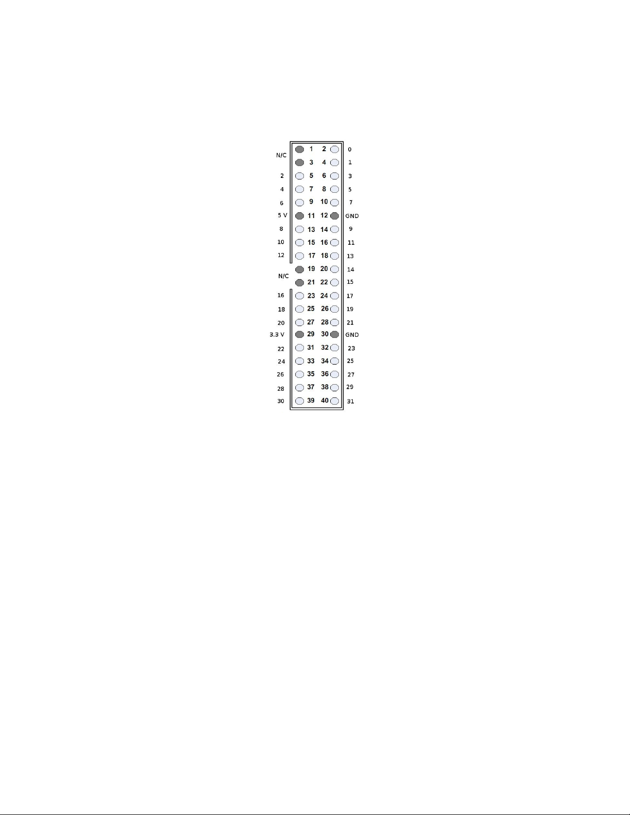
Control Hea er
There are two main types of 40 pin headers on the PB128 board. There are four output headers and one
control header. The control header has its pinout shown in Figure 4. All of the even numbered pins are
grounded, but only the shaded GND pins are connected to the board's ground. The other ground pins are
driven low by the FPGA.
Figure 4: Control Header Pinout
www.spincore.com 8 2011-08-02
PulseBlaster128
Output Hea ers
There are 4 different Output Headers on the PB128. Each Output Header has 32 output channels from
the PulseBlaster core and various power and ground pins. The exact pinout is shown in Figure 5.
Figure 5: Output Header Pinout
www.spincore.com 9 2011-08-02

PulseBlaster128
II. Boar Functionality
PulseBlaster Core
The PulseBlaster128 uses a modified PulseBlaster core with additional modified interrupt
functionality. When the interrupt lines are fixed, the board can be used as a standard PulseBlaster with
128 output channels. All of the information from the standard PulseBlaster manual
(http://www.spincore.com/CD/PulseBlaster/PCI/PB24/PB_Manual.pdf applies in this case.
Interrupts
Overview
The PulseBlaster128 has 256 interrupts controlled by 8 interrupt lines. These lines can be
controlled by hardware through 8 pins on the control header or through software using API functions. The
interrupts are immediate and are always active.
Controlling Interrupts with Software
The PulseBlaster128's custom API comes with two functions that allow the user to control
interrupt states through software and another function to read back the current interrupt state. The
following table explains the functions used to control interrupts in software.
int pb128_set_int_source(int select) Selects the interrupt source. If select is 0 then the
hardware interrupts are used. If select is 1 then
the software interrupts are used.
int pb128_set_sw_int(int interrupt) Sets the software interrupt. If the interrupt source
is set to software, this will cause the board to start
running the selected interrupt if it is not already
running. If the interrupt source is set to hardware,
then this will set the software interrupt without
changing the boards status. That means this
interrupt will become active if the source is
switched to software.
int pb128_get_current_int(void) Returns the current interrupt. This will work when
hardware interrupts are selected and when
software interrupts are selected.
Table 1: Interrupt API functions
Interrupt A resses
When an interrupt is called, the PulseBlaster core reads the interrupt address memory to find the
address of the next instruction to run. This address memory stores one address for each interrupt. It is
programmed using the API through the function in the following table:
int pb128_int_addr_write(int interrupt,
int pb_address)
This function assigns an address of a PulseBlaster
instruction to the given interrupt.
Table 2: Interrupt Address API function
www.spincore.com 10 2011-08-02

PulseBlaster128
Instructions
Instruction Structure
A PulseBlaster instruction is made up of four parts: the output, the op-code, the op-code's data,
and the delay. More information about the available op-codes can be found in the PulseBlaster24 manual
at http://www.spincore.com/CD/PulseBlaster/ PCI/ PB24/PB_Manual.pdf .
Programming Instructions to the PB128
There is one main function in the API that programs instructions to the board, and details about it
can be found in the following table:
int pb128_inst(int addr, int* flag_word, int inst, int inst_data, double time_sec)
int addr The address in PulseBlaster memory to write the
instruction to.
int* flag_word The output associated with the given instruction.
flag_word should be an array of integers with
length 4. The first element in the array,
flag_word[0], is associated with output header 1;
flag_word[1] is associated with output header 2,
and so on. The bits of each element of flag_word
are arranged so that the least significant bit of
flag_word[ ] is bit 0 on header x+1.
int inst The op-code to use for the given instruction. There
are #define statements in pb128usb.h for all of the
op-codes. These defines include CONTINUE, STOP,
BRANCH, LOOP, and so on.
int inst_data This is the data associated with the current op-
code. Many op-codes take no data such as
CONTINUE and STOP, but others such as LOOP and
BRANCH require more information to perform
correctly. See the PulseBlaster24 manual for more
information
double time_sec The delay associated with the instruction in
seconds.
Table 3: Parameter Descriptions for pb128_inst(...)
www.spincore.com 11 2011-08-02


PulseBlaster128
Document Information Page
Document Title: PulseBlaster 128 – Owner's Manual
File Name: PB128-Manual
Revision History: Please contact SpinCore for revision details.
www.spincore.com 13 2011-08-02
Table of contents


