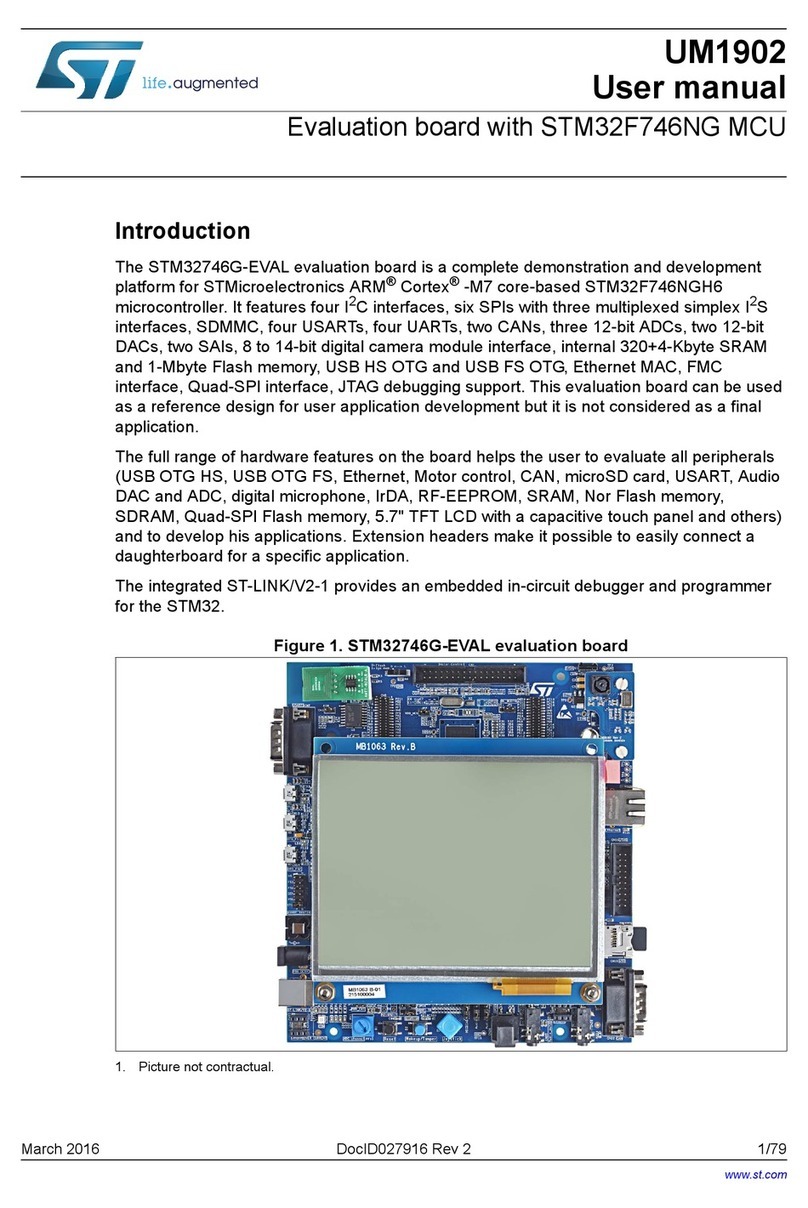
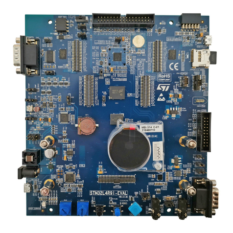
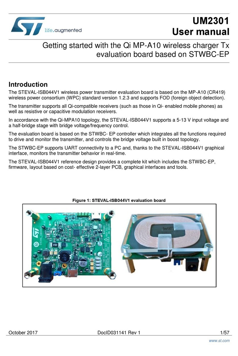
ST STEVAL-MKI132V1 User manual

Looking for a discount?
Check out our current promotions!
This coversheet was created by Verical, a division of Arrow Electronics, Inc. (“Verical”). The attached document was created by the part supplier,
not Verical, and is provided strictly 'as is.' Verical, its subsidiaries, affiliates, employees, and agents make no representations or warranties
regarding the attached document and disclaim any liability for the consequences of relying on the information therein. All referenced brands,
product names, service names, and trademarks are the property of their respective owners.
00000005981LF-000
EOS Power
Buy Now
We have 45,000 LP502030-PCM-NTC-LD-A02554 - EEMB - Lithium Battery Rectangular 3.7V 250mAh Rechargeable in
stock now. Starting at $0.034. This EEMB part is fully warrantied and traceable.
1-855-837-4225
Give us a call
International: 1-555-555-5555 1-415-281-3866
1-415-281-3866
Arrow Electronics,
Verical Division
P.O. Box 740970
Los Angeles, CA 90074-0970
Arrow Electronics, Inc
9201 East Dry Creek Road
Centennial, CO 80112
STEVAL-MKI132V1
STMICROELECTRONICS
Buy Now

January 2013 Doc ID 023744 Rev 1 1/26
UM1579
User manual
STEVAL-MKI132V1- BlueMotion motherboard for MEMS
adapter boards
Introduction
The STEVAL-MKI132V1 (BlueMotion) motherboard is designed to provide the user with a
complete ready-to-use platform for the demonstration of MEMS devices mounted on
adapter boards.
This STEVAL-MKI132V1 demonstration board uses an STM32F103TB microcontroller and
an SPBT2532C2.AT Bluetooth
®
module; it functions as a bridge between the sensor on the
adapter board and the PC. It is possible to connect the BlueMotion to the PC using the
Bluetooth module and using the Unico graphical user interface (GUI), downloadable from
the ST website, or dedicated software routines for customized applications.
This user manual describes the hardware included with the demonstration board and
provides the information required to install and run the demonstration board user interface.
For details regarding the features of each sensor, please refer to the datasheets available for
each individual device.
www.st.com

Contents UM1579
2/26 Doc ID 023744 Rev 1
Contents
1 Demonstration board description . . . . . . . . . . . . . . . . . . . . . . . . . . . . . . 3
2 BlueMotion board installation . . . . . . . . . . . . . . . . . . . . . . . . . . . . . . . . . 8
2.1 Establishing Bluetooth connection . . . . . . . . . . . . . . . . . . . . . . . . . . . . . . . 8
3 Supported MEMS adapter boards . . . . . . . . . . . . . . . . . . . . . . . . . . . . . 12
4 Supported commands . . . . . . . . . . . . . . . . . . . . . . . . . . . . . . . . . . . . . . 13
4.1 Getting started . . . . . . . . . . . . . . . . . . . . . . . . . . . . . . . . . . . . . . . . . . . . . 13
4.2 Supported commands . . . . . . . . . . . . . . . . . . . . . . . . . . . . . . . . . . . . . . . 13
4.2.1 Commands list and description . . . . . . . . . . . . . . . . . . . . . . . . . . . . . . . 14
4.2.2 Digital output accelerometers: supported commands . . . . . . . . . . . . . . 19
4.2.3 Digital output gyroscopes: supported commands . . . . . . . . . . . . . . . . . 20
4.2.4 Digital output magnetometers: supported commands . . . . . . . . . . . . . . 20
4.3 Quick start . . . . . . . . . . . . . . . . . . . . . . . . . . . . . . . . . . . . . . . . . . . . . . . . 21
5 Schematic diagrams . . . . . . . . . . . . . . . . . . . . . . . . . . . . . . . . . . . . . . . . 22
6 Bill of materials . . . . . . . . . . . . . . . . . . . . . . . . . . . . . . . . . . . . . . . . . . . . 23
7 Revision history . . . . . . . . . . . . . . . . . . . . . . . . . . . . . . . . . . . . . . . . . . . 25

UM1579 Demonstration board description
Doc ID 023744 Rev 1 3/26
1 Demonstration board description
The BlueMotion is a complete demonstration board that allows the demonstration of both
digital and analog MEMS sensors. Thanks to its DIL 24 connector, a wide range of MEMS
adapter boards can be used.
The block diagram of the demonstration board is shown in Figure 1.
Figure 1. Demonstration board block diagram
As shown in Figure 1, the BlueMotion demonstration board is based on the STM32F103TB
microcontroller and can be connected to the PC through Bluetooth. Data coming from the
MEMS sensor connected to the board can be read through the PC GUI provided with the
board.
The BlueMotion can be flashed with compatible firmware using an SWD connector or a
UART connector. See www.st.com/mems for new firmware releases.
The following steps are required to flash the board using UART:
1. Connect the BlueMotion to the PC using a UART connector (use the FS and ST pins of
the J2 connector shown in Figure 10).
2. Set the BOOT0 pin of the DIL 24 device adapter high.
3. Power up the board.
4. Use the STM32 flash loader utility to establish a UART connection with the BlueMotion.
The recommended settings are shown in Figure 2.
STM32F103TB
µC
MEMS
device Bluetooth
UART
Interrupt LEDs
General Purpose LEDs
DIL 24
Connector
I2C
AM14726V1

Demonstration board description UM1579
4/26 Doc ID 023744 Rev 1
Figure 2. Connecting BlueMotion using UART
Download the hexadecimal file of the firmware on BlueMotion using the STM32 flash loader
utility. For further details, refer to the utility’s user manual.
Figure 3. Downloading firmware using UART
AM14752V1
AM14753V1

UM1579 Demonstration board description
Doc ID 023744 Rev 1 5/26
Figure 4. Connecting BlueMotion using UART
The BlueMotion also integrates one general purpose LED, and two LEDs connected directly
to the interrupt pins of the digital adapters.
The top view and the bottom view of the full board are shown in Figure 5 and Figure 6
respectively.
AM14754V1

Demonstration board description UM1579
6/26 Doc ID 023744 Rev 1
Figure 5. Board top view
Figure 6. Board bottom view
The BlueMotion demonstration board can be used with the Unico GUI interface which allows
simple interaction with the sensor. The steps required for establishing a Bluetooth
connection with the board and accessing it are discussed in the following sections.
FT
ref 2
ref 1
ref 3
ref 4
ref 5
ref 6
AM14727V1
AM14728V1

UM1579 Demonstration board description
Doc ID 023744 Rev 1 7/26
In Figure 5 some of the main components placed on the top layer of the BlueMotion board
are highlighted.
●
The dual power supply connector J1 (Figure 5, ref 1) can be used to supply power in
one of the two possible modes. Pin 2 on must be connected to ground. The board can
be powered with either a 1.5 V supply, e.g. an AA battery, connected to Pin 1 or with a
supply in the range 3.5 V - 6.0 V. connected to Pin 3.
●
The SWD connector J3 can (Figure 5, ref 2) be used to program the BlueMotion board.
●
Jumper JP1 allows the user to measure the sensor current consumption by connecting
a multimeter in series with its terminals when a 1.5 V power supply is used (Figure 5,
ref 3).
●
Jumper JP2 allows the user to measure the sensor current consumption by connecting
a multimeter in series with its terminals when a power supply in the range 3.5 V - 6.0 V
is used (Figure 5, ref 4).
BlueMotion also integrates three LEDs:
●
LED D5 (Figure 5, ref 5) is a general purpose LED and is used to indicate some
firmware states.
●
LEDs D6 and D7 (Figure 5, ref 6) are directly connected to the interrupt pins of the
MEMS digital adapters (if available on the sensor mounted on the adapter board).

BlueMotion board installation UM1579
8/26 Doc ID 023744 Rev 1
2 BlueMotion board installation
The software package can be downloaded from the st.com website and includes the
following directory structure:
●
FIRMWARE: it contains the source code of the firmware of the BlueMotion board
together with the corresponding binary file that can be flashed to the board.
The section below describes the procedure for establishing a Bluetooth connection with the
BlueMotion board.
2.1 Establishing Bluetooth connection
A Bluetooth connection to the BlueMotion board can be established in three steps:
searching the BlueMotion device, pairing it and connecting to it. To search the device, open
the “Bluetooth Places” using the Bluetooth software on your PC and click on “Search
Devices“. The BlueMotion board should appear with the name “eMotion BT”, as shown in
Figure 7.

BlueMotion board installation UM1579
10/26 Doc ID 023744 Rev 1
Figure 8. Pairing the BlueMotion board
The next step is to connect to the BlueMotion board. Click on the “eMotion BT” icon and
then click on the “Bluetooth Serial Port” icon, as shown in Figure 9. In this example the
board is assigned the port “COM26”. The BlueMotion board is now connected and it can be
accessed through the assigned port.
AM14730V1

UM1579 BlueMotion board installation
Doc ID 023744 Rev 1 11/26
Figure 9. Connecting to the BlueMotion board
AM14731V1

Supported MEMS adapter boards UM1579
12/26 Doc ID 023744 Rev 1
3 Supported MEMS adapter boards
Table 1 below provides a complete list of supported adapter boards.
Table 1. List of supported MEMS adapter boards
Adapter board Device
STEVAL-MKI089V1 LIS331DLH
STEVAL-MKI105V1 LIS3DH
STEVAL-MKI106V1 LSM303DLHC
STEVAL-MKI107V1 L3G4200D
STEVAL-MKI107V2 L3GD20
STEVAL-MKI108V1 9AXISMODULE v1 [LSM303DLHC + L3G4200D]
STEVAL-MKI108V2 9AXISMODULE v2 [LSM303DLHC + L3GD20]
STEVAL-MKI110V1 AIS328DQ
STEVAL-MKI122V1 LSM330DLC
STEVAL-MKI123V1 LSM330D
STEVAL-MKI303V1 LSM303D

UM1579 Supported commands
Doc ID 023744 Rev 1 13/26
4 Supported commands
The microcontroller mounted on the BlueMotion board is equipped with dedicated firmware
that supports a set of commands which allows either the digital or the analog output MEMS
sensor to be controlled and permits the acquisition of the measured data. The firmware also
handles the communication between the board and the PC through a Bluetooth connection.
These features allow the user to easily write their own applications to exploit the capabilities
of the sensor chosen.
This section describes the commands that are supported by the firmware for the
microcontroller of the BlueMotion demonstration board.
4.1 Getting started
Before using the commands supported by the firmware, the following procedure must be
performed:
1. Connect the BlueMotion to the PC using Bluetooth.
2. Launch an application which allows commands to be sent through the virtual serial
port. The remainder of this document assumes the use of the “Microsoft
®
HyperTerminal” program available with the Windows
®
XP operating system.
3. Create a new connection, enter a name (e.g. “BlueMotion”), and click “OK”.
4. In the “Connect Using” field, select the Bluetooth serial COM port to which the
BlueMotion has been connected, and click “OK”.
5. In port settings, set bits per second to 115200, data bits to 8, parity to none, stop bits to
1, and flow control to none. Click “OK”.
6. On the “HyperTerminal” application window choose “files” > “properties” > “settings”,
then click on the “ASCII Setup” button.
7. Select “Send line ends with line feeds” and “Echo typed characters locally”.
8. Click the “OK” button to close the “ASCII Setup” window.
9. Click the “OK” button to close the “Properties” window.
Once this procedure has been completed the user can utilize the commands described in
the following sections by typing them into the “HyperTerminal” window.
4.2 Supported commands
The firmware supports a wide range of MEMS adapters; the next section reports the
complete list of supported commands (see Table 2) and their description.
Then, the list of commands (split into sections) available for each sensor supported by the
BlueMotion firmware is reported.

Supported commands UM1579
14/26 Doc ID 023744 Rev 1
4.2.1 Commands list and description
Note: IR: interrupt byte; FC: FIFO control register; FS: FIFO source register.
Table 2. Supported commands list
Command Description Returned value
*setdbXXXVY Selects firmware according to the adapter
connected
*start Starts continuous data acquisition (see Table 3)
*debug Returns the output data in readable text format (see Table 4)
*stop Stops data acquisition
*Zon Forces 3-state
*Zoff Exits from 3-state
*dev Device name e.g.: LIS3DH
*ver Firmware version e.g.: V1.0
*rAA Accelerometer register read e.g.: RAAhDDh
*wAADD Accelerometer register write
*grAA Gyroscope register read e.g.: GRAAhDDh
*gwAADD Gyroscope register write
*mrAA Magnetometer register read e.g.: MRAAhDDh
*mwAADD Magnetometer register write
*single It gets a single X, Y, and Z data acquisition (see Table 4)
*list Prints the list of MKIs supported e.g.: MKI105V1
*listdev Prints the list of devices supported e.g.: LIS3DH
*echoon Activates the write verbose mode e.g.: RAAhDDh
*echooff Deactivates the write verbose mode
*fifostr Accelerometer “FIFO Stream” mode enable st 0 0 0 0 0 0 IR FC FS
*fifomde Accelerometer “FIFO mode” mode enable st 0 0 0 0 0 0 IR FC FS
*fifotrg Accelerometer “Stream-to-FIFO” mode enable st 0 0 0 0 0 0 IR FC FS
*fiforst Accelerometer “Reset” mode enable st 0 0 0 0 0 0 IR FC FS
*gfifostr Gyroscope “FIFO Stream” mode enable st 0 0 0 0 0 0 IR FC FS
*gfifomde Gyroscope “FIFO mode” mode enable st 0 0 0 0 0 0 IR FC FS
*gfifotrg Gyroscope “Stream-to-FIFO” mode enable st 0 0 0 0 0 0 IR FC FS
*gfiforst Gyroscope “Reset” mode enable st 0 0 0 0 0 0 IR FC FS
*gfifobts Gyroscope “Bypass-to-FIFO” enable st 0 0 0 0 0 0 IR FC FS

UM1579 Supported commands
Doc ID 023744 Rev 1 15/26
Set demonstration board
The command *setdbxxxvy selects the part of the firmware able to handle the adapter board
sensor connected to the board. e.g., in order to select the firmware for the LIS3DH the
command must be: setdb105V1.
Start command
The *start command initiates the continuous data acquisition. When this command is sent to
the device, it returns a string of bytes (plus carriage return and line feed) similar to “st OUT1
OUT2 OUT3 IR BT”.
The first two bytes are always the ASCII char “s” and “t” which correspond to the
hexadecimal values {73h 74h}.
OUT1, OUT2, and OUT3 are the bytes that contain the values measured at device outputs;
if the output data is represented on more than 8 bits, OUT1, OUT2, and OUT3 are split into
two bytes: high byte (e.g.: “XH”) and low byte (e.g.: “XL”).
IR contains the interrupt bytes and BT contains the bytes that describe the state of the
buttons integrated on the board.
Specifically, bit#0 of the “BT” data corresponds to the status of the SW1 button on the
demonstration board: it is set to 1 when the SW1 is pressed (otherwise 0). Bit#1 has the
same behavior but is dedicated to the SW2.
Before sending the *start command, the device must be out from 3-state and some registers
must be configured according to user needs, therefore, *start must be preceded by a *zoff
and some “Register Write” commands.
Table 3 shows the format of the string returned for each device when a *start command is
sent.
Note: XH: X axis output high byte (same for Y axis, Z axis, P pressure, and TEMP temperature).
XL: X axis output low byte (same for Y axis, Z axis, P pressure, and TEMP temperature).
Table 3. Returned values for *start command
STEVAL # (device) Returned value
STEVAL-MKI089V1 (LIS331DLH)
STEVAL-MKI105V1 (LIS3DH)
STEVAL-MKI107V1 (L3G4200D)
STEVAL-MKI107V2 (L3GD20)
STEVAL-MKI110V1 (AIS328DQ)
s t XH XL YH YL ZH ZL int1 int2 sw1|sw2 \r \n
STEVAL-MKI106V1 (LSM303DLHC)
STEVAL-MKI303V1 (LSM303D)
s t A_XH A_XL A_YH A_YL A_ZH A_ZL M_XH M_XL
M_YH M_YL M_ZH M_ZL A_int1 A_int2 sw1|sw2 \r \n
STEVAL-MKI108V1 (9AXISMODULEv1)
STEVAL-MKI108V2 (9AXISMODULEv2)
s t A_XH A_XL A_YH A_YL A_ZH A_ZL
G_XH G_XL G_YH G_YL G_ZH G_ZL
M_XH M_XL M_YH M_YL M_ZH M_ZL
A_int1 A_int2 sw1|sw2 \r \n
STEVAL-MKI122V1 (LSM330DLC)
STEVAL-MKI123V1 (LSM330D)
s t A_XH A_XL A_YH A_YL A_ZH A_ZL
G_ X H G_X L G_YH G _ YL G_ ZH G_ZL
A_int1 A_int2 G_int1 G_int2 sw1|sw2 \r \n

Supported commands UM1579
16/26 Doc ID 023744 Rev 1
Debug command
The *debug command starts the continuous data acquisition in debug mode. When this
command is sent to the board, it returns the output values measured by the device
formatted in a readable text format. The values shown on the screen correspond to the LSB
data shown as a decimal number.
Table 4 shows the format of the string returned for each device when a *debug command is
sent.
Stop command
The *stop command interrupts any acquisition session that has been started with either the
*start or *debug commands.
Zon and Zoff
The *Zon and *Zoff commands are employed, respectively, to put into 3-state the
STM32F103TB microcontroller mounted on the demonstration board. These commands
allow the isolation of the sensor from the microprocessor and allow the user to interact with
the sensor in a pure analog way.
By default, when the board is first turned on, the lines are in 3-state mode and the user is
required to send the *Zoff command to allow communication between the sensor and the
microcontroller. If Zoff has not been launched, the firmware ignores any other commands.
Device name
The *dev command retrieves the name of the adapter connected to the demonstration
board. The returned value is, for example, “
LIS3DH
”.
Firmware version
The *ver command queries the demonstration board and returns the version of the firmware
loaded in the microprocessor, for example, “V1.0”.
Table 4. Returned values for *debug command
STEVAL # (device) Returned value
STEVAL-MKI089V1 (LIS331DLH)
STEVAL-MKI105V1 (LIS3DH)
STEVAL-MKI110V1 (AIS328DQ)
X=XXXXX Y=YYYYY Z=ZZZZZ
STEVAL-MKI106V1 (LSM303DLHC)
STEVAL-MKI303V1 (LSM303D)
AX=XXXXX AY=YYYYY AZ=ZZZZZ
MX=XXXXX MY=YYYYY MZ=ZZZZZ
STEVAL-MKI107V1 (L3G4200D)
STEVAL-MKI107V2 (L3GD20) P=PPPPP R=RRRRR Y=YYYYY
STEVAL-MKI108V1 (9AXISMODULEV1)
STEVAL-MKI108V2 (9AXISMODULEV2)
AX=XXXXX AY=YYYYY AZ=ZZZZZ
MX=XXXXX MY=YYYYY MZ=ZZZZZ
GX=XXXXX GY=YYYYY GZ=ZZZZZ
STEVAL-MKI122V1 (LSM330DLC)
STEVAL-MKI123V1 (LSM330D)
AX=XXXXX AY=YYYYY AZ=ZZZZZ
GX=XXXXX GY=YYYYY GZ=ZZZZZ

UM1579 Supported commands
Doc ID 023744 Rev 1 17/26
Accelerometer register read
The *rAA command allows the contents of the accelerometer registers in the demonstration
board to be read. AA, expressed as a hexadecimal value and written in upper case,
represents the address of the register to be read.
Once the read command is issued, the board returns RAAhDDh, where AA is the address
sent by the user and DD is the data present in the register.
For example, to read the register at address 0x20, the user issues the command *r20, which
returns, e.g., R20hC7h.
Accelerometer register write
The *wAADD command allows writing to the contents of the accelerometer registers of the
demonstration board. AA and DD, expressed as hexadecimal values and written in upper
case, represent, respectively, the address of the register and the data to be written. For
example, to write 0xC7 to the register at address 0x20, the user issues the command
*w20C7.
Gyroscope register read
The *grAA command allows the contents of the gyroscope registers of the demonstration
board to be read. AA, expressed as hexadecimal value and written in upper case,
represents the address of the register to be read.
Once the read command is issued, the board returns GRAAhDDh, where AA is the address
sent by the user and DD is the data present in the register.
For example, to read the register at address 0x20, the user issues the command *gr20,
which returns, e.g., GR20hC7h.
Gyroscope register write
The *gwAADD command allows writing to the contents of the gyroscope registers of the
demonstration board. AA and DD, expressed as hexadecimal values and written in upper
case, represent, respectively, the address of the register and the data to be written. To write
0xC7 to the register at address 0x20, for example, the user issues the command *gw20C7.
Magnetometer register read
The *mrAA command allows the contents of the magnetometer registers in the
demonstration board to be read. AA, expressed as a hexadecimal value and written in upper
case, represents the address of the register to be read.
Once the read command is issued, the board returns MRAAhDDh, where AA is the address
sent by the user and DD is the data present in the register.
For example, to read the register at address 0x00, the user issues the command *mr00,
which returns, e.g., MR00h10h.
Magnetometer register write
The *mwAADD command allows writing to the contents of the magnetometer registers of
the demonstration board. AA and DD, expressed as hexadecimal values and written in
upper case, represent, respectively, the address of the register and the data to be written. To
write 0x20 to the register at address 0x01, for example, the user issues the command
*mw0120.

Supported commands UM1579
18/26 Doc ID 023744 Rev 1
Single acquisition
The *single command may be used to read just one set of data. It requires the sensor to be
well configured and once invoked, returns the read values of one data sample.
The format of the returned value is exactly the same as the *debug command (Table 4), in
fact, the *debug command is used for continuous data acquisition purposes whereas a
*single command returns just one set of data.
List
The *list command returns the list of MKI adapters supported by the firmware, printed in
ASCII format.
Listdev
The *listdev command returns the list of devices supported by the firmware, printed in ASCII
format.
Echo on
The *echoon command is used to activate the write command verbose mode. Once this
command is launched, after every write command the firmware automatically performs also
a read of the register just written. This function is useful to check if the write has succeeded.
For instance, if the *echoon command is launched, after a *w2027 it results R2027.
Echo off
The *echooff command stops the write command verbose mode.
Accelerometer FIFO Stream mode enable
The *fifostr command is used to enable the accelerometer FIFO Stream mode. For more
details see the AN3308 application note.
Accelerometer FIFO mode enable
The *fifomde command is used to enable the accelerometer FIFO mode. For more details
see the AN3308 application note.
Accelerometer Stream-to-FIFO mode enable
The *fifotrg command enables the accelerometer Stream-to-FIFO mode. For more details
see the AN3308 application note.
Accelerometer FIFO Reset enable
The *fiforst command enables the accelerometer FIFO Reset mode. For more details see
the AN3308 application note.
Gyroscope FIFO Stream mode enable
The *fifostr command is used to enable the gyroscope FIFO Stream mode.
Gyroscope FIFO mode enable
The *gfifomde command is used to enable the gyroscope FIFO mode.

UM1579 Supported commands
Doc ID 023744 Rev 1 19/26
Gyroscope Stream-to-FIFO mode enable
The *gfifotrg command enables the gyroscope Stream-to-FIFO mode.
Gyroscope FIFO Reset enable
The *gfiforst command enables the gyroscope FIFO Reset mode.
Gyroscope FIFO Bypass-to-Stream enable
The *gfifobts command enables the gyroscope Bypass-to-Stream mode.
4.2.2 Digital output accelerometers: supported commands
Table 5 below lists the commands supported by the devices/demonstration boards including
a digital output accelerometer.
Note: IR: interrupt byte; FC: FIFO control register; FS: FIFO source register.
Table 5. Digital output accelerometers: supported commands list
Command Description Returned value
*setdbXXXVY Selects firmware according to the adapter
connected
*start Starts continuous data acquisition (see Table 3)
*debug Returns the output data in readable text format (see Table 4)
*stop Stops data acquisition
*Zon Forces 3-state
*Zoff Exits from 3-state
*dev Device name e.g.: LIS3DH
*ver Firmware version e.g.: V1.0
*rAA Accelerometer register read e.g.: RAAhDDh
*wAADD Accelerometer register write
*single It gets a single X, Y, and Z data acquisition (see Table 4)
*list Prints the list of MKIs supported e.g.: MKI105V1
*listdev Prints the list of devices supported e.g.: LIS3DH
*echoon Activates the write verbose mode e.g.: RAAhDDh
*echooff Deactivates the write verbose mode
*fifostr
(1)
1. Available only for devices with embedded FIFO.
Accelerometer “FIFO Stream” mode enable st 0 0 0 0 0 0 IR FC FS
*fifomde
(1)
Accelerometer “FIFO mode” mode enable st 0 0 0 0 0 0 IR FC FS
*fifotrg
(1)
Accelerometer “Stream-to-FIFO” mode enable st 0 0 0 0 0 0 IR FC FS
*fiforst
(1)
Accelerometer “Reset” mode enable st 0 0 0 0 0 0 IR FC FS
Table of contents
Other ST Motherboard manuals

ST
ST X-NUCLEO-IDB04A1 User manual

ST
ST EVAL-L99H02QF User manual

ST
ST STM3240G-EVAL User manual

ST
ST STM3220F-EVAL User manual

ST
ST EVAL-L99DZ200 User manual

ST
ST STEVAL-IHM020V1 User manual

ST
ST EVAL-IBD002-35W User manual

ST
ST EVAL-FDA903U-SA User manual

ST
ST STEVAL-IME015V1 User manual

ST
ST STFPC311 User manual

ST
ST EVALKITSTKNX User manual

ST
ST EVALST-3PHISOSD User manual

ST
ST SPC58NG-DISP User manual

ST
ST STEVAL-ILH007V1 User manual

ST
ST eMotion STEVAL-MKI109V1 User manual

ST
ST STM32746G-EVAL User manual
ST
ST STEVAL-PCC008V1 User manual

ST
ST STEVAL-LVLP01 User manual

ST
ST STM3240G-EVAL User manual

ST
ST STEVAL-ISW001V1 User manual