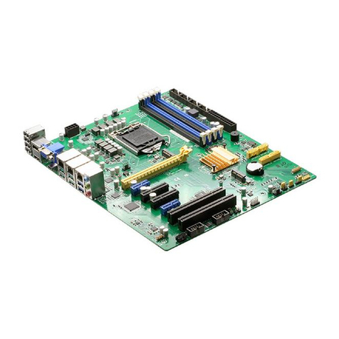
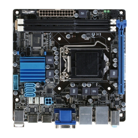
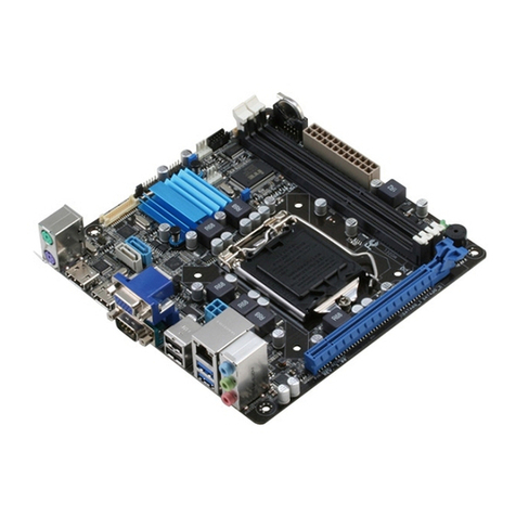
Aaeon EMB-CV2 User manual

Mini-ITX
E M B - C V 2
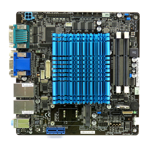
EMB-CV2
Intel®AtomTM D2550 B3 Processor
Mini-ITX
10/100/1000Base-TX Ethernet
8 USB2.0, 2 COM, 8-bit Digital I/O
6 SATA 3.0 Gb/s, 1 PCI-E[x4]
EMB-CV2 Manual Rev.A 1st Ed.
March 11, 2014

Mini-ITX
E M B - CV2
i
Copyright Notice
This document is copyrighted, 2014. All rights are reserved. The
original manufacturer reserves the right to make improvements to
the products described in this manual at any time without notice.
No part of this manual may be reproduced, copied, translated, or
transmitted in any form or by any means without the prior written
permission of the original manufacturer. Information provided in this
manual is intended to be accurate and reliable. However, the
original manufacturer assumes no responsibility for its use, or for
any infringements upon the rights of third parties that may result
from its use.
The material in this document is for product information only and is
subject to change without notice. While reasonable efforts have
been made in the preparation of this document to assure its
accuracy, the original manufacturer assumes no liabilities resulting
from errors or omissions in this document, or from the use of the
information contained herein.
The original manufacturer reserves the right to make changes in the
product design without notice to its users.

Mini-ITX
E M B - CV2
ii
Acknowledgments
All other products’name or trademarks are properties of their
respective owners.
AMI is a trademark of American Megatrends Inc.
CompactFlash™is a trademark of the Compact Flash
Association.
Intel®and Atom™are trademarks of Intel®Corporation.
Microsoft Windows®is a registered trademark of Microsoft
Corporation.
ITE is a trademark of Integrated Technology Express, Inc.
IBM, PC/AT, PS/2, and VGA are trademarks of International
Business Machines Corporation.
SoundBlaster is a trademark of Creative Labs, Inc.
Please be notified that all other products’name or trademarks
not be mentioned above are properties of their respective
owners.

Mini-ITX
E M B - CV2
iii
Packing List
(Standard, not bulk pack)
Before you begin installing your card, please make sure that
the following materials have been shipped:
1 Cable Set (SATA Cable, SATA Power Cable)
1 Metal I/O Bracket
1 Product CD
1 EMB-CV2
If any of these items should be missing or damaged, please
contact your distributor or sales representative immediately.

Mini-ITX
E M B - CV2
iv
Contents
Chapter 1 General Information
1.1 Features .................................................................... 1-2
1.2 Specifications ............................................................ 1-3
Chapter 2 Quick Installation Guide
2.1 Safety Precautions....................................................2-2
2.2 Location of Connectors and Jumpers ....................... 2-3
2.3 Mechanical Drawing..................................................2-4
2.4 List of Jumpers..........................................................2-6
2.5 List of Connectors .....................................................2-7
2.6 Setting Jumpers ........................................................2-9
2.7 AT/ATX Power Type Selection (AT_ATX_SEL1)....2-10
2.8 Clear CMOS/ RTC (CLRTC1).................................2-10
2.9 LVDS Backlight Brightness Control (LVDSBRC1)..2-10
2.10 LVDS Panel Voltage Selection (LVDS_PVSEL1).2-10
2.11 LVDS Inverter Voltage Selection (LVDS_PVSEL1)
.......................................................................................2-10
2.12 Serial Port 2 External Power Selection (CN10) ....2-11
2.13 Front Panel Connector (FP1)................................2-11
2.14 LVDS Output (Single Channel18/24-bit) (LVDS1) 2-11
2.15 SATA Power Connector (SATA_PWR1)...............2-12
2.16 USB 4 /5 / 6 / 7 Pin Header (USB45_1) (USB67_1)
.......................................................................................2-12

Mini-ITX
E M B - CV2
v
2.17 Digital I/O (CN2)....................................................2-12
2.18 PS/2 Keyboard Mouse Pin Header (KBMS1) .......2-12
2.19 CPU Fan & System Fan Connector (CPU_FAN1)
(SYS_FAN1)..................................................................2-13
2.20 ATX AUX in +12V Connector (ATX1) ...................2-13
2.21 ATX Power Board Control Pin Header (CN11).....2-13
2.22 COM Port Connector (COM2)...............................2-13
Chapter 3 AMI BIOS Setup
3.1 System Test and Initialization. .................................. 3-2
3.2 AMI BIOS Setup........................................................3-3
Chapter 4 Driver Installation
4.1 Installation………………………………………..……..4-3
Appendix A Programming The Watchdog Timer
A.1 Programming ............................................................A-2
A.2 W83627DHG Watchdog Timer Initial Program.........A-6
Appendix B I/O Information
B.1 I/O Address Map.......................................................B-2
B.2 1st MB Memory Address Map.....................................B-4
B.3 IRQ Mapping Chart...................................................B-5
B.4 DMA Channel Assignments......................................B-7
Appendix C Mating Connector
C.1 List of Mating Connectors and Cables......................C-2

Mini-ITX
E M B - CV2
vi
Appendix D AHCI & RAID Settings
D.1 Setting AHCI.............................................................D-2
D.2 Setting RAID.............................................................D-9

Mini-ITX
E M B - CV2
Chapter 1 General Information 1- 1
General
Information
Chapter
1

Mini-ITX
E M B - CV2
Chapter 1 General Information 1-2
1.1 Features
Onboard Intel®Atom™ D2550 Processor
Intel®ICH10R
Intel®Graphics Media Accelerator Supports DirectX 10,
OpenGL 3.0
DDR3 800/1066 SO-DIMM x 2, Max. 4GB
VGA, Dual Channel 24-bit LVDS, DVI, Dual Independent
Display
Dual Gigabit Ethernet
COM x 2 (RS232 x 1, RS232/422/485 x 1)
USB2.0 x 8, Serial ATA 3Gb/s x 6
PCIe [x4] x 1
6 CH Audio Channel

Mini-ITX
E M B - CV2
Chapter 1 General Information
1-3
1.2 Specifications
System
Processor
Intel® Atom™ D2550 processor
Dual Core 1.86GHz (TDP 10W)
System Memory
Single Channel with two 204-pin
DDR3 800 /1066 SODIMM, up to
4 GB, non-ECC, un-buffered
memory with 0.6mm pitch SMT
socket
Chipset
Intel®ICH10R
I/O Chipset
Winbond W83627DHG-P
Ethernet
Realtek 8111E for
10/100/1000Base-TX, RJ-45 x 2
BIOS
AMI BIOS, 32MB ROM
Wake On LAN
Yes
Watchdog Timer
System reset: 1~255 steps
programmable
H/W Status Monitoring
Supports Power Supply Voltage,
Fan Speed, and Temperature
Monitoring
Expansion Interface
PCIe [x4] x 1
Battery
Lithium 3V/220mAh with vertical
socket type
Power Requirement
DC 12V (selectable AT/ATX mode
for power on)
Board Size
6.7”(L) x 6.7”(W)
(170 mm x 170 mm)
Gross Weight
1.1 lb (0.5 Kg)
Operating Temperature
32˚F~ 140˚F (0˚C ~ 60˚C)

Mini-ITX
E M B - CV2
Chapter 1 General Information 1-4
Storage Temperature
-40˚F ~176°F (-40°C ~80°C)
Operating Humidity
5%~95%RH, non-condensing
Display
Chipset
Intel® Graphics Media Accelerator
3650
(Gfx frequency 640MHz / DX10.1)
Resolution
Up to 1920 x 1200 / 60Hz at
355MHz Max for CRT
Up to 1920 x 1080 / 60Hz, 24bpps
for Dual Channel LVDS (from eDP
w/chrontel CH7511)
Up to 1920 x1200 / 60Mz for DVI
LVDS Interface
Dual Channel 24-bit LVDS
Video Interface
VGA x 1, DVI-D x 1
I/O
Storage
SATA 3.0Gb/s x 6 with RAID
0/1/5/10
Serial Port
RS-232 (COM1) x 1 via D-sub 9
connector on rear IO
RS-232/422/485 (COM2) x 1 via
D-sub 9 connector on rear IO with
+12V / +5V powered
Parallel Port
SPP/EPP
USB
USB 2.0 x 8
USB 1 & 2 via double deck USB
and RJ-45 connector on rear IO
USB 3 & 4 via double deck USB
and RJ-45 connector on rear IO
USB 5-8 via internal 2 x 5 pin

Mini-ITX
E M B - CV2
Chapter 1 General Information
1-5
2.0mm pin header
Digital I/O
Supports 8-bit (Programmable)
PS/2 Port
Keyboard/ Mouse x 1
Audio
Line-in, Mic-in, Line-out

Mini-ITX
E M B - CV2
Chapter 2 Quick Installation Guide 2 - 1
Quick
Installation
Guide
Chapter
2

Mini-ITX
E M B - CV2
Chapter 2 Quick Installation Guide 2 - 2
2.1 Safety Precautions
Always completely disconnect the power cord
from your board whenever you are working on
it. Do not make connections while the power is
on, because a sudden rush of power can
damage sensitive electronic components.
Always ground yourself to remove any static
charge before touching the board. Modern
electronic devices are very sensitive to static
electric charges. Use a grounding wrist strap at
all times. Place all electronic components on a
static-dissipative surface or in a static-shielded
bag when they are not in the chassis

Mini-ITX
E M B - CV2
Chapter 2 Quick Installation Guide 2 - 3
2.2 Location of Connectors and Jumpers

Mini-ITX
E M B - CV2
Chapter 2 Quick Installation Guide 2 - 4
2.3 Mechanical Drawing
Component Side

Mini-ITX
E M B - CV2
Chapter 2 Quick Installation Guide 2 - 5
Solder Side

Mini-ITX
E M B - CV2
Chapter 2 Quick Installation Guide 2 - 6
2.4 List of Jumpers
The board has a number of jumpers that allow you to configure your
system to suit your application.
The table below shows the function of each of the board's jumpers:
Label
Function
AT_ATX_SEL1
AT/ATX Power Type Select
CLRTC1
Clear CMOS / RTC
LVDSBRC1
LVDS Backlight Brightness Control
LVDS_PVSEL1
LVDS Panel Voltage Select
LVDS_PVSEL1
LVDS Inverter Voltage Select
CN10
Serial port2 external power select
FP1
Front panel connector

Mini-ITX
E M B - CV2
Chapter 2 Quick Installation Guide 2 - 7
2.5 List of Connectors
The board has a number of connectors that allow you to configure your
system to suit your application.
The table below shows the function of each of the board's connectors:
Label
Function
LVDS1
LVDS output (single channel18/24bit)
VGA1
Analog CRT display connector
DVI1
DVI display connector
SATA0
SATA port0 connector
SATA1
SATA port1 connector
SATA2
SATA port2 connector
SATA3
SATA port3 connector
SATA4
SATA port4 connector
SATA5
SATA port5 connector
SATA_PWR1
SATA power connector
PCIE4X_1
PCI-Express[x4] slot
USB45_1
USB4 & 5 pin header
USB67_1
USB6 & 7 pin header
CN2
GPIO pin header
CN10
SMBUS & COM2 external power pin
COM1
RS-232 Serial port 1 connector
COM2
RS-232/422/485 serial port 2 connector
KBMS1
PS/2 keyboard mouse pin header

Mini-ITX
E M B - CV2
Chapter 2 Quick Installation Guide 2 - 8
CPU_FAN1
CPU fan connector
SYS_FAN1
System fan connector
FP1
Front panel pin header
AUDIO1
Audio phone jack
LAN1_USB01
RJ-45 Ethernet 1 & USB 0/1 connector
LAN2_USB23
RJ-45 Ethernet 2 & USB 2/3 connector
ATX1
ATX AUX in +12v Connector
DC1
DC 12V in
CN11
ATX power board control pin header
NOTE: The +12V Power connector (Label: DC_PWR) is lockable Jack
type with screw. Please refer the inner and outer diameter
dimension of connector as below to choose suitable adaptor.
Table of contents
Other Aaeon Motherboard manuals

Aaeon
Aaeon SBC-770 User manual

Aaeon
Aaeon ATX-Q670A User manual

Aaeon
Aaeon EMB-H110B User manual

Aaeon
Aaeon FSB-B75H User manual

Aaeon
Aaeon IMBM-H110A User manual

Aaeon
Aaeon FSB-960H User manual

Aaeon
Aaeon Compact Board PCM-9452 User manual

Aaeon
Aaeon UP-CHT01 User manual

Aaeon
Aaeon EMB-H81A User manual

Aaeon
Aaeon EMB-BT1 User manual

Aaeon
Aaeon EMB-9458T User manual

Aaeon
Aaeon PCM-QM77 User manual

Aaeon
Aaeon ITP11 User manual

Aaeon
Aaeon GENE-9455 Rev.B User manual

Aaeon
Aaeon PCM-6892 Rev.B User manual

Aaeon
Aaeon FSB-H81H User manual

Aaeon
Aaeon HSB-965P User manual

Aaeon
Aaeon GENE-CV05 User manual

Aaeon
Aaeon GENE-9655 User manual

Aaeon
Aaeon IMBM-Q87A User manual