SpinCore Technologies PulseBlasterESR QuadCore 250 Turbo User manual

PulseBlasterESR QuadCore™ 250 (Turbo)
Owner’s Manual
SpinCore Technologies, Inc.
http://www.spincore.com

PulseBlasterESR QuadCore 250 (Turbo)
Congratulations and thank you for choosing a design from SpinCore
Technologies, Inc.
We appreciate our business!
At SpinCore we aim to full support the needs of our customers. If
ou are in need of assistance, please contact us and we will strive to
provide the necessar support.
© 2009 SpinCore Tec nologies, Inc. All rig ts reserved.
SpinCore Tec nologies, Inc. reserves t e rig t to make c anges to t e product(s) or information erein wit out notice. PulseBlaster-
QuadCore™, PulseBlaster™, SpinCore, and t e SpinCore Tec nologies, Inc. logos are trademarks of SpinCore Tec nologies, Inc. All ot er
trademarks are t e property of t eir respective owners.
SpinCore Tec nologies, Inc. makes every effort to verify t e correct operation of t e equipment. T is equipment version is not intended for
use in a system in w ic t e failure of a SpinCore device will t reaten t e safety of equipment or person(s).
www.spincore.com 2 02/17/09

PulseBlasterESR QuadCore 250 (Turbo)
Table of Contents
I. Introduction ............................................................................................................................................ 4
Product Overview ............................................................................................................................ 4
Programming Paradigm ................................................................................................................... 4
II. Installing and Using Your Pulse lasterESR QuadCore oard ............................................................ 5
Installation........................................................................................................................................ 5
General API Programming Information........................................................................................... 5
III. Test Programs ..................................................................................................................................... 6
IV. Available Options ............................................................................................................................... 7
V. Contact Information ............................................................................................................................. 7
VI. Document Information Page ............................................................................................................... 8
www.spincore.com 3 02/17/09

PulseBlasterESR QuadCore 250 (Turbo)
I. Introduction
Product Overview
T e SpinCore PulseBlasterESR QuadCore 250 (Turbo) is a 4-Core PulseBlaster design implemented on
PulseBlasterESR PCI boards. T e 4-Core design uses four of SpinCore's proprietary PulseBlaster processor
cores on a single c ip. T is new design allows t e user to program and run independent programs on eac core,
in parallel, w ile maintaining precise timing sync ronization between t e cores.
Eac individual PulseBlaster core as one output bit (flag/c annel) available as a TTL signal on t e
corresponding BNC connector of t e PC bracket. For example, t e output bit for Core0 is on t e BNC0
connector closest to t e PCI slot as seen in Figure 1.
Figure 1: SpinCore PulseBlasterESR QuadCore design topology and connector locations. All four
PulseBlaster cores and triggering circuitry ave been implemented on a single c ip.
All four cores are driven by t e same, single clock source, 250 MHz. T ey can be sync ronized to start at
t e same time and run four unique pulse programs/sequences concurrently. At 250 MHz, t e available
resolution of eac pulse/delay/interval is 4 ns (one clock cycle), t e minimum pulse/delay/interval lengt is 5
clock cycles, or 20 ns, and t e maximum pulse/delay/interval lengt is 229 clock cycles (~2.15 seconds). Eac
core as 1k (1024) memory words available for writing pulse programs, i.e., t ere can be up to 1024 lines in your
pulse program per core.
T e basic arc itecture of t e individual PulseBlaster processor cores is described in multiple documents,
including t e Manuals for PulseBlaster and PulseBlasterESR boards, available on-line at t e SpinCore's website
www.spincore.com.
Programming Paradigm
Eac core can be individually programmed wit an arbitrary sequence of intervals. Eac interval can be of
unique lengt , and up to 1024 intervals can be accommodated per sequence. Since eac interval can be a
pulse or a delay, t e programming of eac core involves t e loading of two basic parameters per interval: t e
output state (logical O or 1), and t e duration of t e state (in nanoseconds, microseconds, milliseconds).
Eac core can be independently selected for programming and program execution. T e low-level interaction
is t roug t e set of specific functions in t e dedicated Application Programming Interface (API) package called
SpinAPI, available for download on SpinCore's website www.spincore.com. Virtually any ig er-level
application package (Java, C, Matlab, LabVIEW, Visual Basic, etc.) can interact wit t e board t roug t e
provided SpinAPI functions.
www.spincore.com 4 02/17/09
NC3
NC2
NC1
NC0
Clock
and
triggering
circuitry
Pulse laster Core1
Pulse laster Core2
Pulse laster Core3
Pulse laster Core0

PulseBlasterESR QuadCore 250 (Turbo)
II. Installing and Using Your PulseBlasterESR QuadCore Board
Installation
To install t e board you must complete t e following t ree steps:
- Install t e latest SpinAPI version, available at t e address ttp://spincore.com/support/spinapi/
- S ut down computer, insert PulseBlasterESR QuadCore Turbo 250 card, and fasten t e PC bracket
securely wit a screw.
- Power up and follow t e installation prompts.
Now you are ready to run t e test programs provided in t e SpinAPI package.
Note: W en installing t e ardware, t e device may s ow up as PulseBlasterESR-Pro, t is is OK.
Note: T e PulseBlaster Interpreter t at is included in t e SpinAPI package CANNOT be used to program t e
PBESR QuadCore board.
Note: To compile and run your own C programs, you may want to download t e SpinAPI Tools package t at
contains a pre-configured compiler; t e SpinAPI Tools package is also available for download at t e URL above.
General API Programming Information
Four test programs (executables and t eir C source files) are available for testing t e boards. Assuming t e
default installation, t e test programs will be available on t e computer at t e following location: Windows
“Start” → All Programs → SpinAPI → PBESR_QuadCore (t e default installation location is: C:\Program
Files\SpinCore\SpinAPI\PBESR-QuadCore). T e .c files can be modified and recompiled to create custom test
programs.
Eac core can be programmed wit a unique pulse program by using t e pb_select_core(unsigned int
core_sel) function, w ere t e lower four bits of core_sel are used to select t e cores (bit0 corresponds to Core0,
bit1 corresponds to Core1, etc) and multiple combinations are acceptable (i.e. a value of 0xF, or 15 will select all
four cores).
T e overall system timing is based on Core0 in order to ensure t at all cores are precisely sync ronized. T is
requires t at Core0 be t e last core (or part of t e group of last cores) t at is programmed before starting
execution of t e pulse program(s).
Two separate SpinAPI functions are used to write pulse programs for t e PulseBlasterESR QuadCore:
pb_4C_inst(int flag, double lengt ) and pb_4C_stop(void).
pb_4C_inst(...) is used to define t e pulse program. T e input parameter 'flag' must eit er be '1' to turn t e
flag on, or '0' to turn t e flag off. T e input parameter 'lengt ' defines t e time interval for t e current instruction
and must be multiplied by 'ns' (nanoseconds), 'us' (microseconds), or 'ms' (milliseconds).
pb_4C_stop() defines t e end of t e pulse program.
It is ver important to note t at because t e sync ronization is based on Core0, if Core0's pulse program is
still running, t e ot er cores may continue to output values from memory even after t e pb_4C_stop() instruction.
Also, if Core0's pulse program stops, it will cause all ot er cores to stop even if t ey ave not completed t eir
pulse program. For t is reason it is ig ly recommended t at t e pulse program for Core0 as t e longest
duration, and t e pulse programs for t e ot er cores are extended using t e pb_4C_inst(...) instruction wit a '0'
output so t at t e total duration of eac pulse program is t e same causing t em to stop at exactly t e same
time.
www.spincore.com 5 02/17/09

PulseBlasterESR QuadCore 250 (Turbo)
III. Test Programs
Four test programs ave been packaged wit t e SpinAPI driver suite to illustrate t e basic features and
functionality of t e PulseBlasterESR QuadCore 250 (Turbo) design. All programs can be found following t e
pat Windows “Start” -> All Programs -> SpinCore -> SpinAPI -> PBESR_QuadCore.
Example 1
T e first test program, PB_QuadCore_Example1.exe, demonstrates t at all four cores (c annels) can
generate identical pulses t at are precisely sync ronized.
Excerpt from t e code, to program one of t e cores (Core3), is as follows:
pb_select_core(0x8); // This line selects Core3 for programming, notice hexadecimal coding
pb_start_programming (PULSE_PROGRAM);//This command is needed to begin writing your pulse program
pb_4C_inst (1, 20.0 * ns); // logical “high” for 20 ns (can be modified as required)
pb_4C_inst (0, 20.0 * ns); // logical “low” for 20 ns (can be modified as required)
pb_4C_stop (); // This signifies the end of a pulse program
pb_stop_programming ();//T is command is needed at t e end of eac pulse program
In Example 1, all cores are programmed wit identical content – one 20 ns pulse. Later in t e program, all
four cores are triggered at t e same time. T e resulting output s ould be one 20 ns pulse on eac BNC output
connector, and all four pulses s ould appear simultaneously on all four c annels.
NOTE: W en attac ing an oscilloscope to t e board to observe t e pulses, care s ould be taken to use
cables of t e same type and lengt for eac c annel, as skew can be induced due to propagation delays.
Conversely, any in erent variations in on-c ip propagation delays can be compensated by appropriate variations
in cable lengt .
Example 2
T e second test program, PB_QuadCore_Example2.exe, demonstrates a group of simple output patterns
t at differ for eac core but start simultaneously.
Example 3
T e t ird test program, PB_QuadCore_Example3.exe, demonstrates t e versatility and simplicity of
programming of t e 4-Core design. In t is program, eac core is loaded wit a unique pulse program t at allows
one of t e cores to start generating a pulse w ile ot er cores are in t e middle of outputting t eir pulses. Any
combination of pulses is possible as long as t e minimum pulse time (20 ns) and pulse setting resolution (4 ns)
are observed.
Example 4
T e fourt test program, PB_QuadCore_Example4.exe s ows t e generation of a s ort pulse followed by a
long, 600 ms delay on one c annel w ile t ree ot er c annels generate trains of unique sequences of pulses,
eac wit fixed pulse widt but varying intervals between pulses.
www.spincore.com 6 02/17/09

PulseBlasterESR QuadCore 250 (Turbo)
IV. Available Options
A number of off-t e-s elf and custom options are available for t is product.
1.Oven Controlled Clock Oscillator, w en sub-ppm stability is required.
2.Hig er clock frequency (custom design).
3.Additional TTL output bits per core (custom design).
Please contact SpinCore Tec nologies, Inc. for more information, questions, or suggestions. We look
forward to earing from you and elping you in your projects. Please find our contact information below.
V. Contact Information
SpinCore Tec nologies, Inc.
4623 NW 53rd Avenue, Suite 5
Gainesville, Florida 32653, USA
P one: +1-352-271-7383
Fax: +1-352-371-8679
Website: ttp://www.spincore.com
www.spincore.com 7 02/17/09

PulseBlasterESR QuadCore 250 (Turbo)
VI. Document Information Page
Document Title: PulseBlasterESR QuadCore 250 (Turbo)
Document Number: DA-2
File Name: PBESR_QuadCore_Manual
Document Location: S:\Product_Folders\Manuals\PBESR_QuadCore
Original Document Created: C ris Hett, 2009/01/22
Revision History: C ris Hett, 2009/02/03 – Edited Figure 1 to more correctly
display board arc itecture, wit timing based on Core0.
Updated formatting.
www.spincore.com 8 02/17/09
Table of contents
Other SpinCore Technologies Pulse Generator manuals
Popular Pulse Generator manuals by other brands

DORIC
DORIC OTPG 4 user manual
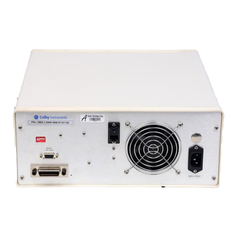
Colby Instruments
Colby Instruments PDL-100A Operating and programming manual
AVTECH ELECTROSYSTEMS LTD.
AVTECH ELECTROSYSTEMS LTD. AVMP-2-B instructions
Avtech
Avtech AVMR-2D-B instructions
AVTECH ELECTROSYSTEMS LTD.
AVTECH ELECTROSYSTEMS LTD. AVR-8A-B instructions
Quantum Composers
Quantum Composers 9520 Series operating manual
