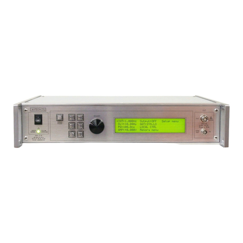
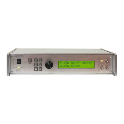
SPECIFICATIONS
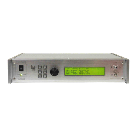
Model1AVOZ-H1-B
Amplitude voltage (each output)
current (sum of all outputs)
< 3V to 60V, adjustable
0 to 6A
Minimum load impedance (parallel
combination of loads on all outputs)
10 Ω
The load must be non-inductive2
Maximum number of 50Ω loads (if
outputs used separately) 5
Pulse width4200 ns - 200 ms, or DC.
Rise & fall times (20%-80%) < 100 ns
Pulse repetition frequency (PRF) 1 Hz to 50 kHz, adjustable
Maximum duty cycle 80% in the pulse mode. 100% in the DC mode.
Output impedance (approx.) 0.1 Ohms
Average output power 60V × 6A = 360 Watts, maximum
Droop < 5%, at maximum pulse width and maximum amplitude
Polarity Positive or negative (specify3)
GPIB & RS-232 control1Standard on -B units.See http //www.avtechpulse.com/gpib for details.
LabView drivers Check http //www.avtechpulse.com/labview for availability and downloads
Ethernet port, for remote control using
VXI-11.3, ssh, telnet, & web
Included. Recommended as a modern alternative to GPIB / RS-232.
See http //www.avtechpulse.com/options/vxi for details.
Settings resolution The resolution of the timing parameters (pulse width, delay, period) varies,
but is always better than 0.15% of (|set value| + 20 ns).
The amplitude resolution is < 0.1% of the maximum amplitude.
Settings accuracy Typically ± 3% (plus ±1V or ± 2 ns) after 10 minute warmup. For high-accuracy applications
requiring traceable calibration, verify the output parameters with a calibrated oscilloscope5.
Propagation delay < 200 ns (Ext trig in to pulse out)
Jitter ± 100 ps ± 0.03% of sync delay (Ext trig in to pulse out)
Trigger modes Internal trigger, external trigger (TTL level pulse, > 10 ns, 1 kΩ input impedance),
front-panel “Single Pulse” pushbutton, or single pulse trigger via computer command.
Variable delay. Sync to main out 0 to 1.0 seconds, for all trigger modes (including external trigger).
Sync output > +3 Volts, > 50 ns, will drive 50 Ohm loads
Gate input Synchronous or asynchronous, active high or low, switchable.
Suppresses triggering when active.
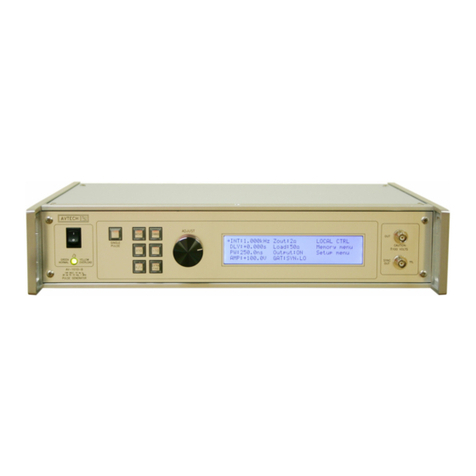
Output connectors
(see above for quantity)
Mainframe Multiple SMA female connectors, for connection to an equal number of
separate 50 Ohm loads, or for connection to the output module.
Optional output module Multiple SMA female connectors for connection to mainframe, and
one Type-N female connector for connection to a low impedance load.
Number of output connectors 5
Optional cable kit 5 cables (RG58C/U cables, 5 feet / 152 cm). Add -CK5 to model number.
Optional output module (for combining
multiple outputs on to a single Type-N
connector)
Add -OM5 to the model number.
Other connectors Trig, Gate, Sync BNC
Power requirement 100 - 240 Volts, 50 - 60 Hz, 500 Watts.
Dimensions Mainframe 100 x 430 x 375 mm (3.9 x 17 x 14.8”),
-OM5 optional output module 28 x 36 x 58 mm (1.1 x 1.4 x 2.3”)
Chassis material Anodized aluminum, with blue plastic trim
Temperature range +5°C to +40°C
1) -B suffix indicates IEEE-488.2 GPIB and RS-232 control of pulse amplitude, pulse width, delay and PRF. (See http //www.avtechpulse.com/gpib).
2) For applications where additional resistance must be added in series with the device under test, Avtech recommends connecting multiple Ohmite (www.ohmite.com) OY-
series ceramic composition resistors in parallel to create a high-power, low-inductance effective resistance. These resistors can be purchased readily at http //www.digi-
key.com.
3) Indicate desired polarity by suffixing model number with -P or -N (i.e. positive or negative) or -PN for dual polarity option.
4) In the external trigger mode, the output pulse width may also be set to track the input pulse width (PW OUT = PWIN mode). The user must take care to respect the pulse width
and duty cycle limits.
5) These instruments are provided with a basic calibration checksheet, showing a selection of measured output parameters. These measurements are performed with
equipment that is calibrated on a regular basis by a third-party ISO/IEC 17025 2005 accredited calibration laboratory. However, Avtech itself does not claim any
accreditation. For applications requiring traceable performance, use a calibrated measurement system rather than relying on the accuracy of the pulse generator settings.
