Spirax Sarco IPC6 User manual

IM-P705-02 CTLS Issue 3 1
IPC6 and IPC6 ATEX Electro-pneumatic Convertor
1. Safety information
2. General product
information
3. Installation
4. Commissioning
5. Maintenance
6. Fault finding
7. Approvals
© Copyright 2021
3440450/3
IPC6 and IPC6 ATEX
Electro-pneumatic Convertor
Installation and Maintenance Instructions
IM-P705-02
CTLS Issue 3

IM-P705-02 CTLS Issue 3
2
IPC6 and IPC6 ATEX Electro-pneumatic Convertor

IM-P705-02 CTLS Issue 3 3
IPC6 and IPC6 ATEX Electro-pneumatic Convertor
Safe operation of these products can only be guaranteed if they are properly installed,
commissioned, used and maintained by qualified personnel (see Section 1.11) in compliance with
the operating instructions. General installation and safety instructions for pipeline and plant
construction, as well as the proper use of tools and safety equipment must also be complied with.
WARNING: The maximum process fluid temperature must be suitable for use if the
unit is to be used in any potential explosive atmosphere. For the device maintenance
in a potentially explosive atmosphere, we recommend the usage of tools which do
not produce and / or propagate sparks.
1.1 Explosion Proof Warnings
Please ensure the unit is being used and installed in conformity with local, regional, and national
explosion proof environment.
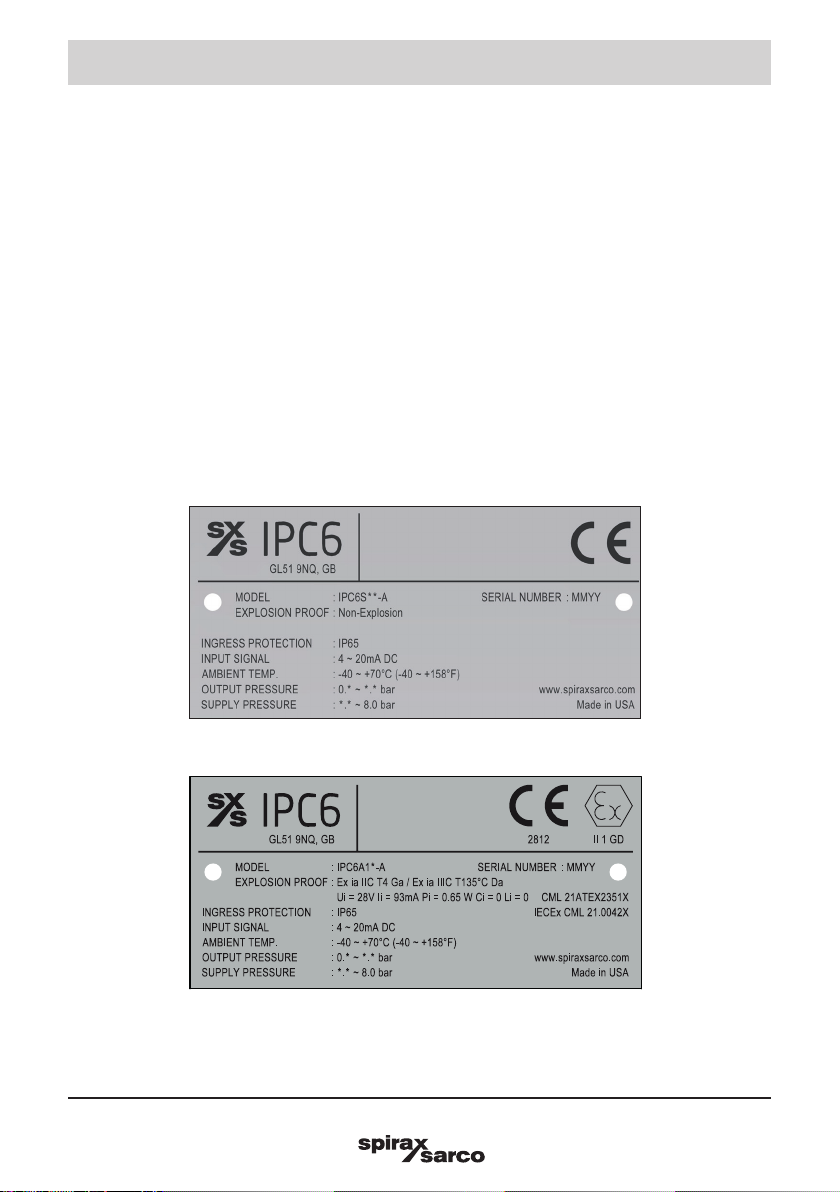
- Refer to "7. Approvals"
- Explosion proof type of cables and gaskets should be used, when explosion gases are present
at the installation site.
- Power should be turned of before removing the plug.
- There is risk of explosion due to static electricity charge. Static electricity charge may develop
when cleaning the product with a dry cloth. It is imperative to avoid static electricity charge
in the hazardous environment. If cleaning the surface of the product is needed, must use a
damp cloth.
- Under certain extreme circumstances, the non-metallic parts incorporated in the enclosure of
this equipment may generate an ignition capable level of electrostatic charge. Therefore, the
equipment shall not be installed in a location where the external conditions are conducive to
the build-up of electrostatic charge on such surfaces. In addition, the equipment shall only
be cleaned with a damp cloth.
- The enclosures are manufactured from of aluminium alloy. In rare cases, ignition sources
due to impact and friction sparks could occur. This shall be considered during installation,
particularly if the equipment in installed in a zone 0 location.
- When the product is used and maintained in a dusty environment, corresponding cleaning
measures should be taken regularly to prevent the accumulation of dust on the surface, but
compressed air must not be used for blowing.
- This equipment contains no user-replaceable parts and is not intended to be repaired by the
user. Repair of the equipment is to be carried out by the manufacturer, or their approved agents,
in accordance with the applicable code of practice.
- The installation, use and maintenance of the product should also comply with
GB3836.13-2013 Explosive atmospheres
Part 13: Equipment repair, overhaul and reclamation GB/T3836.15-2017 Explosive
atmospheres
Part 15: Electrical installations design, selection and erection GB/T3836.16-2017 Explosive
atmospheres
Part 16: Electrical installations inspection and maintenance GB50257-2014 Code for
construction and acceptance of electric device for explosive atmospheres and fire hazard
electrical equipment installation engineering GB15577-2018 Safety regulations for dust
explosion prevention and protection.
1. Safety information

IM-P705-02 CTLS Issue 3
4
IPC6 and IPC6 ATEX Electro-pneumatic Convertor
1.2 Intended use
Referring to the Installation and Maintenance Instructions, product markings and Technical
Information Sheet, check that the product is suitable for the intended use / application. These
products comply with the requirements of the Directive 2014/34/EU (ATEX) for the use of equipment
in potentially explosive atmospheres.
1.3 Access
Ensure safe access and if necessary a safe working platform (suitably guarded)before attempting
to work on the product. Arrange suitable lifting gear if required.
1.4 Lighting
Ensure adequate lighting, particularly where detailed or intricate work is required.
1.5 Hazardous liquids or gases in the pipeline
Consider what is in the pipeline or what may have been in the pipeline at some previous time.
Consider: flammable materials, substances hazardous to health, extremes of temperature.
1.6 Hazardous environment around the product
Consider: explosion risk areas, lack of oxygen (e.g. tanks, pits), dangerous gases, extremes of
temperature, hot surfaces, fire hazard (e.g. during welding), excessive noise, moving machinery.
The convertor is suitable for installation in Zone 0 or Zone 1 or Zone 2 ( Gas ) Zone 20 or Zone 21
or Zone 22 ( Dust ).
1.7 The system
Consider the effect on the complete system of the work proposed. Will any proposed action (e.g.
closing isolation valves, electrical isolation) put any other part of the system or any personnel
at risk?
Dangers might include isolation of vents or protective devices or the rendering ineffective of
controls or alarms. Ensure isolation valves are opened and closed progressively to avoid system
shocks.
1.8 Pressure systems
Ensure that any pressure is isolated and safely vented to atmospheric pressure. Consider double
isolation (double block and bleed) and the locking or labelling of closed valves. Do not assume
that the system has depressurised even when the pressure gauge indicates zero.
1.9 Temperature
Allow time for temperature to normalise after isolation to avoid the danger of burns.
1.10 Tools and consumables
Before starting work ensure that you have suitable tools and/ o r consumables available.
Use only genuine Spirax Sarco replacement parts.

IM-P705-02 CTLS Issue 3 5
IPC6 and IPC6 ATEX Electro-pneumatic Convertor
1.11 Protective clothing
Consider whether you and/ or others in the vicinity require any protective clothing to protect
against the hazards of, for example, chemicals, high l/ ow temperature, radiation, noise, falling
objects, and dangers to eyes and face.
1.12 Permits to work
All work must be carried out or be supervised by a suitably competent person.Installation and
operating personnel should be trained in the correct use of the product according to the Installation
and Maintenance Instructions.
Where a formal 'permit to work' system is in force it must be complied with. Where there is no such
system, it is recommended that a responsible person should know what work is going on and, where
necessary, arrange to have an assistant whose primary responsibility is safety.
Post 'warning notices' if necessary.
1.13 Handling
Manual handling of large and/ or heavy products may present a risk of injury. Lifting, pushing,
pulling, carrying or supporting a load by bodily force can cause injury particularly to the back.
You are advised to assess the risks taking into account the task, the individual, the load and the
working environment and use the appropriate handling method depending on the circumstances
of the work being carried out.
1.14 Residual hazards
In normal use the external surface of the product may be hot.
1.15 Freezing
Provision must be made to protect products which are not self-draining against frost damage in
environments where they may be exposed to temperatures below freezing point.
1.16 Disposal
Unless otherwise stated in the Installation and Maintenance Instructions, this product is recyclable
and no ecological hazard is anticipated with its disposal providing due care is taken.
1.17 Returning products
Customers and stockists are reminded that under EC Health, Safety and Environment Law,
when returning products to Spirax Sarco they must provide information on any hazards and the
precautions to be taken due to contamination residues or mechanical damage which may present a
health, safety or environmental risk. This information must be provided in writing including Health
and Safety data sheets relating to any substances identified as hazardous or potentially hazardous.

IM-P705-02 CTLS Issue 3
6
IPC6 and IPC6 ATEX Electro-pneumatic Convertor
2.1 Introduction
The IPC6 is a Electro-pneumatic convertor requiring an air supply between 1.5 and 8 bar g. It will convert a
4 -20mA signal into an air pressure signal. The IPC6 can be mounted directly onto a flat surface, or using
mounting kits for panel, wall or pipe mounting.
2.2 Label Description
-Model, Indicates the model number and additional symbols.
-Explosion proof, Indicates certified explosion proof grade.
-Ingress Protection, Indicates enclosure protection grade.
-Input signal, Indicates input signal range.
-Ambient temperature, Indicates the allowable ambient temperature for explosion proof.
-Output Pressure, Indicates the output pressure range.
-Supply Pressure, Indicates the supply pressure range.
-Serial number, Indicates manufactured month and year.
2. General product information
Fig. 1a Nameplate - Non-Explosion Proof
Fig. 1b Nameplate - ATEX / IECEx

IM-P705-02 CTLS Issue 3 7
IPC6 and IPC6 ATEX Electro-pneumatic Convertor
2.3 Operating principle
The IPC6 is an electro-pneumatic device that converts a DC input signal to a pneumatic output. This device
is made up of two sections, the Primary Converting Section and the Pneumatic Relay Section. The Coil
and Suspension Spring, in the Primary Converting Section, is used as a Flapper. Together the Flapper and
Nozzle work to control the signal pressure. The signal pressure acts on the Upper Control Diaphragm, in
the Pneumatic Relay Section, which sets the output pressure. The output pressure is sensed by the Lower
Control Diaphragm, in the Pneumatic Relay Section, which maintains the output pressure.
Fig. 2 IPC6
Flapper and nozzle
Upper control diaphragm
Lower control diaphragm
Primary converting
section
Pneumatic relay
section
Out In
Fig. 1c Nameplate - CCC / NEPSI / ATEX / IECEx
Flapper and nozzle
Upper control diaphragm
Lower control diaphragm
Primary converting
section
Pneumatic relay
section
Out In
Fig. 2 IPC6
Fig. 1c Nameplate - CCC / NEPSI / ATEX / IECEx

IM-P705-02 CTLS Issue 3
8
IPC6 and IPC6 ATEX Electro-pneumatic Convertor
3/4
19.1
1 1/2
38.1
7
20.9 14.9
Fig. 3 Mounting Kit (Included with Unit)
Use two M6
Screws for
Mounting
(not included
in mounting kit)
DIN
EN-50045
35
DIN
EN-50022
DIN
EN-50035
15.6
53/64
20.9
19/32
14.9
32
Fig. 4 DIN Rail Mounting Kit (Included with Unit)
38
19
19
114
21 15 16
34.5
123
7
57
62
3. Installation
The IPC6 is supplied with a wall mounting kit and a DIN Rail Mounting Kit.
Mounting Kit PMK is available when installing the unit on a 2" pipe, see Figure 5.
Fig. 3 Mounting Kit (Included with unit)
Mounting Kit
Includes the following:
Two 10-32 x 5/16" Screws
Mounting Bracket Two ¼" NPT Pipe Plugs
Two 5 mm thick washers
Fig. 4 DIN Rail Mounting Kit (Included with unit)
Din Rail
Mounting
Configuration
shown with
Model IPC6
and DIN EN-50045
3/4
19.1
1 1/2
38.1
7
20.9 14.9
Fig. 3 Mounting Kit (Included with Unit)
Use two M6
Screws for
Mounting
(not included
in mounting kit)
DIN
EN-50045
35
DIN
EN-50022
DIN
EN-50035
15.6
53/64
20.9
19/32
14.9
32
Fig. 4 DIN Rail Mounting Kit (Included with Unit)
38
19
19
114
21 15 16
34.5
123
7
57
62
Use two M6
Screws for
Mounting (not
included in
mounting kit)
DIN
EN-50035
DIN
EN-50045
DIN
EN-50022

IM-P705-02 CTLS Issue 3 9
IPC6 and IPC6 ATEX Electro-pneumatic Convertor
1
21/
.
11/32
8.6
Fig. 5 Mounting Kit (Sold Separately)
89
68
25
25
9
Pneumatic Connection
- Clean all pipelines to remove dirt and scale before installation.
- Apply a minimum amount of pipe compound to the male threads of the fitting only.
- Do not use teflon tape as a sealant.
- Start with the third thread back and work away from the end of the fitting to avoid contaminating the
convertor.
- Install the convertor in the air line.
- The inlet and outlet ports are labeled on the ends of the convertor.
- Tighten connections securely.
- Avoid undersized fittings that will limit the flow through the convertor and cause pressure drop down
stream.
Electric Connection
Make connections as shown in Figure 6.
Note:
Oil free air is required.
Use a filter to remove dirt and liquid in the air line ahead of the convertor.
The user is responsible for insuring that the environment in which the unit will be installed and the operating
gas are compatible with the materials in the convertor.
Fig. 5 Mounting Kit (Sold Separately)
Mounting Kit PMK
includes the following:
Mounting Bracket 2" Pipe Clamp
Two 10-32 x 5/16" Screws
2" Pipe Mounting Configuration shown
with Model IPC6

IM-P705-02 CTLS Issue 3
10
IPC6 and IPC6 ATEX Electro-pneumatic Convertor
Fig. 6
4. Commissioning
4.1 Equipment required for calibration:
Pneumatic Supply capable of delivering up to 10 bar g.
-Current Supply capable of delivering up to 60 mA.
-Pressure gauge capable of a digital readout up to 3 bar g with an accuracy of 0.1%.
-Digital ammeter capable of a readout up to 60 mA with an accuracy of 0.02%.
4.2 Full range operation
Caution:
Over-ranging the Zero Screw can damage unit.
Forward acting mode adjustment
1. Connect the input signal to the convertor as shown in Fig. 6.
Forward Acting Calibration-Zero
2. Apply the minimum input signal and adjust the Zero screw for minimum output pressure.
Turn screw clockwise to increase pressure and counterclockwise to decrease pressure.
Forward Acting Calibration-Span
3. Apply the maximum input signal and adjust the Span screw for maximum output pressure.
Turn screw clockwise to increase pressure and counterclockwise to decrease pressure.
4. Repeat steps 2-3 until the desired output range is obtained.
Reverse Acting Mode Adjustment
5. Connect the input signal to the convertor as shown in Fig. 6.
Reverse Acting Calibration-Zero
6. Apply the minimum input signal and adjust the Zero screw for maximum output pressure.
Turn screw clockwise to increase pressure and counterclockwise to decrease pressure.
Reverse Acting Calibration-Span
7. Apply the maximum input signal and adjust the Span screw for minimum output pressure.
Turn screw clockwise to decrease pressure and counterclockwise to increase pressure.
8. Repeat steps 6-7 until the desired output range is obtained.
Split range operation
All units have the capability to be split ranged or set for any output in the range as long as the Output Span
is equal to or greater than the minimum Span.

IM-P705-02 CTLS Issue 3 11
IPC6 and IPC6 ATEX Electro-pneumatic Convertor
Fig. 6
Note:
Fig. 6
Not used on ATEX intrinsically safe units
Fig. 6
DIN connector
(Forward mode)
WARNING
Read
CAUTION
above
Terminal #3
(NA) not used
Terminal #2
(-) negative
ground
Terminal #1
(+) positive
DIN connector
(Reverse mode)
(NA)
Not used

IM-P705-02 CTLS Issue 3
12
IPC6 and IPC6 ATEX Electro-pneumatic Convertor
5.1 Regular maintenance
1. Drain any build-up within the air supply lter set as impurities such as oil, water and dirt will cause
inconsistent operation.
2. Ensure air supply is at the correct pressure.
3. Wipe the unit with a damp cloth or antistatic products.
5.2 Product return procedure
Please provide the following information with any equipment being returned:
1. Your name, Company name, address and telephone number, order number and invoice and return
delivery address.
2. Description of equipment being returned.
3. Description of the fault.
4. If the equipment is being returned under warranty, please indicate:
i. Date of purchase
ii. Original order number
iii. Serial number
Please return all items to your local Spirax Sarco branch.
Please ensure all items are suitably packed for transit (preferably in the original cartons).
5. Maintenance

IM-P705-02 CTLS Issue 3 13
IPC6 and IPC6 ATEX Electro-pneumatic Convertor
Warning:
Failure of convertor could result in output pressure increasing to supply pressure possibly causing personal
injury or damage to equipment.
Problem Solution (check)
No output
Supply pressure
Clogged orice
Input signal
Pneumatic connections
Low or improper
Span adjust
Zero and span adjust
Supply pressure low
Output leakage
Erratic operation
DC signal
Loose wires or connections
Liquid in air supply
Dirt in magnet gap
6. Fault finding

IM-P705-02 CTLS Issue 3
14
IPC6 and IPC6 ATEX Electro-pneumatic Convertor
7. Approvals
ATEX
Rating : II1 GD Ex ia IIC T4 Ga/Ex ia IIIC T135°C Da
Certification No. : CML 21ATEX2351X
Ambient temperature : -40 ~ +70 °C (-40 ~ +158 °F)
Safety parameters: Ui=28V, Ii=93mA, Pi=0.65W, Ci=0, Li=0
IECEx
Rating : Ex ia IIC T4 Ga/EX ia IIIC T135 °C Da, NEMA4
Certification No. : IECEx CML 21.0042X
Ambient temperature : -40 ~ +70 °C (-40 ~ +158 °F)
Safety parameters: Ui=28V, Ii=93mA, Pi=0.65W, Ci=0, Li=0
CCC / NEPSI
Rating : Ex ia IIC T4 Ga/Ex iaD 20 T135°C
Certification No. : GYJ21.1274X
Ambient temperature : -40 ~ +70 °C (-40~+158 °F)
Safety parameters: Ui=28V, Ii=93mA, Pi=0.65W, Ci=0, Li=0

IM-P705-02 CTLS Issue 3 15
IPC6 and IPC6 ATEX Electro-pneumatic Convertor
spiraxsarco.com EN
Electric to Pressure Transducer (controller)
IPC6
0
0
Spirax Sarco Ltd,
Runnings Road
Cheltenham
GL51 9NQ
United Kingdom
2014/30/EU EMC Directive
2014/34/EU ATEX Directive
0 0
0 0
EMC Directive EN 61326-1:2013
0 0
0 0
ATEX Directive EN IEC 60079-0:2018
0EN 60079-11:2012
0 0
0 0
0 0
0 0
0 0
Notified Body number Performed Certificate
Element Materials Technology
Rotterdam B.V. Voorerf 18, 4824 GN
Breda Netherlands
2812 Issue of Quality Assurance Notification TRAC13QAN0002
CML B.V.
Hoogoorddreef 15 1101BA
Amsterdam, Netherlands
2776 Issue of EC Type examination certificate CML 21ATEX2351X
Additional information:
ATEX coding: II 1 GD Ex ia IIC T4 Ga Ex ia IIIC T135°C Da
0Ta= -40°C to +70°C
On behalf of: Spirax Sarco Ltd,
M Sadler
Cheltenham
2021-06-24
GNP234-EU-C/02 issue 1 (EN)
Name and address of the manufacturer or his
authorised representative:
EU DECLARATION OF CONFORMITY
Apparatus model/Product:
0
0
0
Product Integrity & Compliance Manager
(place and date of issue):
This declaration of conformity is issued under the sole responsibility of the manufacturer.
The object of the declaration described above is in conformity with the relevant Union harmonisation legislation:
References to the relevant harmonised standards used or references to the other technical specifications in relation to which
conformity is declared:
Where applicable, the notified body:
(name, function):
Steam Business Development Engineering
Page 1/1

IM-P705-02 CTLS Issue 3
16
IPC6 and IPC6 ATEX Electro-pneumatic Convertor
This manual suits for next models
1
Table of contents
Other Spirax Sarco Media Converter manuals
Popular Media Converter manuals by other brands

Avermedia
Avermedia ExtremeCap SDI BU111 quick guide

Daxten
Daxten MONITOR SPLITTER installation guide

HEIDENHAIN
HEIDENHAIN TTR ERM 2404 operating instructions

Baumer
Baumer HUBNER BERLIN HG 22 Mounting and operating instructions

OTS
OTS EC1212-X-MINI Series Quick installation guide

Eusso
Eusso UVE7312-MP user manual

Transition Networks
Transition Networks M/GE-ISW-SFP-01-PD user guide

Aus Electronics Direct
Aus Electronics Direct AA6103 user manual

Allied Telesis
Allied Telesis AT-DMC1000/SC installation guide

JMC
JMC YUAN SC6C0N1 AIO user manual

Verint
Verint S1801e Quick installation guide

Cypress
Cypress CDL-165HUB Operation manual