Spirax Sarco FT44 User manual

IM-S02-30 CMGT Issue 14 1
FT43, FT44, FT46 and FT47 Ball Float Steam Traps
1. Safety information
2. General product information
3. Installation
4. Commissioning
5. Operation
6. Maintenance and spare parts
0667050/14
FT43, FT44, FT46 and FT47
Ball Float Steam Traps
Installation and Maintenance Instructions
IM-S02-30
CMGT Issue 14
© Copyright 2022
Printed in GB

IM-S02-30 CMGT Issue 14
2
FT43, FT44, FT46 and FT47 Ball Float Steam Traps
Safe operation of these products can only be guaranteed if they are properly installed, commissioned,
used and maintained by qualified personnel (see Section 1.11) in compliance with the operating
instructions. General installation and safety instructions for pipeline and plant construction, as
well as the proper use of tools and safety equipment must also be complied with.
1.1 Intended use
Referring to the Installation and Maintenance Instructions, name-plate and Technical Information
Sheet, check that the product is suitable for the intended use/application.
The products listed below comply with the requirements of the EU Pressure Equipment Directive/UK
Pressure Equipment (Safety) Regulations and carry the mark when so required.
The products fall within the following Pressure Equipment Directive categories:
Product Group 2
Gases
Group 2
Liquids
FT43
DN15 - DN40 SEP SEP
DN50 1SEP
DN80 - DN100 2SEP
FT44, FT46 and
FT47
DN15 - DN20 SEP SEP
DN25 - DN50 1SEP
DN80 - DN100 (FT44 only) 2SEP
i) The products have been specifically designed for use on steam, air or water/condensate which
are in Group 2 of the above mentioned Pressure Equipment Directive.
ii) Check material suitability, pressure and temperature and their maximum and minimum values.
If the maximum operating limits of the product are lower than those of the system in which it is
being fitted, or if malfunction of the product could result in a dangerous overpressure or
overtemperature occurrence, ensure a safety device is included in the system to prevent such
over-limit situations.
iii) Determine the correct installation situation and direction of fluid flow.
iv) Spirax Sarco products are not intended to withstand external stresses that may be induced by
any system to which they are fitted. It is the responsibility of the installer to consider these
stresses and take adequate precautions to minimise them.
v) Remove protection covers from all connections and protective film from all name-plates, where
appropriate, before installation on steam or other high temperature applications.
1.2 Access
Ensure safe access and if necessary a safe working platform (suitably guarded) before attempting
to work on the product. Arrange suitable lifting gear if required.
1.3 Lighting
Ensure adequate lighting, particularly where detailed or intricate work is required.
1. Safety information

IM-S02-30 CMGT Issue 14 3
FT43, FT44, FT46 and FT47 Ball Float Steam Traps
1.4 Hazardous liquids or gases in the pipeline
Consider what is in the pipeline or what may have been in the pipeline at some previous time.
Consider: flammable materials, substances hazardous to health, extremes of temperature.
1.5 Hazardous environment around the product
Consider: explosion risk areas, lack of oxygen (e.g. tanks, pits), dangerous gases, extremes of
temperature, hot surfaces, fire hazard (e.g. during welding), excessive noise, moving machinery.
1.6 The system
Consider the effect on the complete system of the work proposed. Will any proposed action (e.g.
closing isolation valves, electrical isolation) put any other part of the system or any personnel at
risk?
Dangers might include isolation of vents or protective devices or the rendering ineffective of
controls or alarms. Ensure isolation valves are turned on and off in a gradual way to avoid system
shocks.
1.7 Pressure systems
Ensure that any pressure is isolated and safely vented to atmospheric pressure. Consider double
isolation (double block and bleed) and the locking or labelling of closed valves. Do not assume
that the system has depressurised even when the pressure gauge indicates zero.
1.8 Temperature
Allow time for temperature to normalise after isolation to avoid danger of burns.
1.9 Tools and consumables
Before starting work ensure that you have suitable tools and/or consumables available. Use only
genuine Spirax Sarco replacement parts.
1.10 Protective clothing
Consider whether you and/or others in the vicinity require any protective clothing to protect against
the hazards of, for example, chemicals, high/low temperature, radiation, noise, falling objects, and
dangers to eyes and face.
1.11 Permits to work
All work must be carried out or be supervised by a suitably competent person.Installation and
operating personnel should be trained in the correct use of the product according to the Installation
and Maintenance Instructions.
Where a formal 'permit to work' system is in force it must be complied with. Where there is no such
system, it is recommended that a responsible person should know what work is going on and,
where necessary, arrange to have an assistant whose primary responsibility is safety.
Post 'warning notices' if necessary.

IM-S02-30 CMGT Issue 14
4
FT43, FT44, FT46 and FT47 Ball Float Steam Traps
1.12 Handling
Manual handling of large and/or heavy products may present a risk of injury. Lifting, pushing,
pulling, carrying or supporting a load by bodily force can cause injury particularly to the back.
You are advised to assess the risks taking into account the task, the individual, the load and the
working environment and use the appropriate handling method depending on the circumstances
of the work being done.
1.13 Residual hazards
In normal use the external surface of the product may be very hot. If used at the maximum permitted
operating conditions the surface temperature of some products may reach temperatures in excess
of 300 °C (572 °F).
Many products are not self-draining. Take due care when dismantling or removing the product from
an installation (refer to 'Maintenance instructions').
1.14 Freezing
Provision must be made to protect products which are not self-draining against frost damage in
environments where they may be exposed to temperatures below freezing point.
1.15 Disposal
Unless otherwise stated in the Installation and Maintenance Instructions, this product is recyclable
and no ecological hazard is anticipated with its disposal providing due care is taken.
1.16 Returning products
Customers and stockists are reminded that under EC Health, Safety and Environment Law, when
returning products to Spirax Sarco they must provide information on any hazards and the precautions
to be taken due to contamination residues or mechanical damage which may present a health,
safety or environmental risk. This information must be provided in writing including Health and
Safety data sheets relating to any substances identified as hazardous or potentially hazardous.
1.17 Working safely with cast iron products on steam
Cast iron products are commonly found on steam and condensate
systems. If installed correctly using good steam engineering
practices, it is perfectly safe. However, because of its mechanical
properties, it is less forgiving compared to other materials such
as SG iron or carbon steel. The following are the good engineering
practices required to prevent waterhammer and ensure safe
working conditions on a steam system.
Safe handling
Cast Iron is a brittle material. If the product is dropped during
installation and there is any risk of damage the product should
not be used unless it is fully inspected and pressure tested by the
manufacturer.

IM-S02-30 CMGT Issue 14 5
FT43, FT44, FT46 and FT47 Ball Float Steam Traps
Prevention of water hammer
Steam trapping on steam mains:
Steam Mains - Do's and Don'ts:
Steam Steam
Flow Flow
30 - 50 metre intervals
Gradient 1:100
Gradient 1:100
Trap set
Trap set
Trap set
Condensate Condensate Condensate
Steam
Steam

IM-S02-30 CMGT Issue 14
6
FT43, FT44, FT46 and FT47 Ball Float Steam Traps
Prevention of tensile stressing
Pipe misalignment:
Installing products or re-assembling after maintenance:
Thermal expansion:
Do not over tighten.
Use correct torque gures.
1
1
4 2
3
8
2
6
3
7
Flange bolts should be gradually tightened across
diameters to ensure even load and alignment.
Guides
Guides
Limit
rods
Limit rods
Fixing point
Medium
distance
Small
lateral
movement
Small lateral
movement
Large lateral
movement
Large lateral
movement
Short
distance Fixing point
Axial
movement
Axial movement
Guides
Guides
5
4

IM-S02-30 CMGT Issue 14 7
FT43, FT44, FT46 and FT47 Ball Float Steam Traps
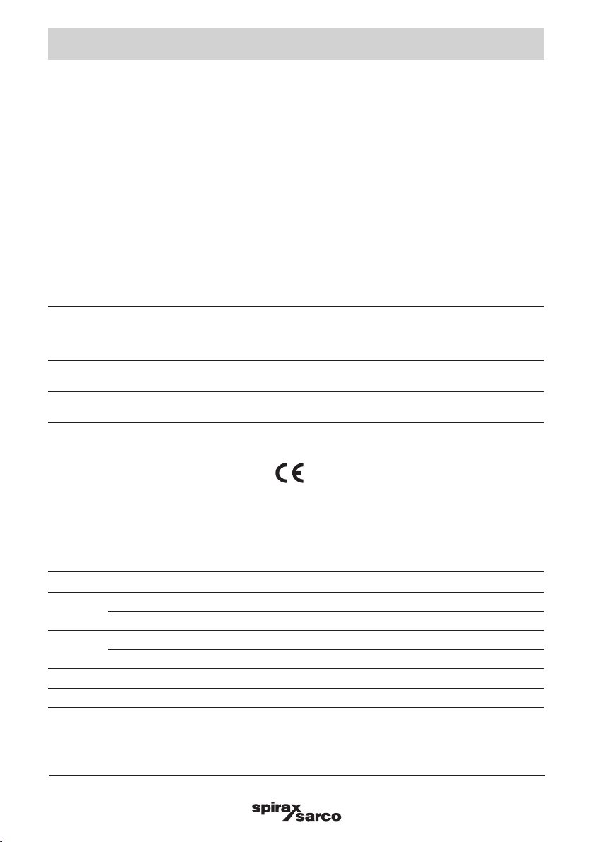
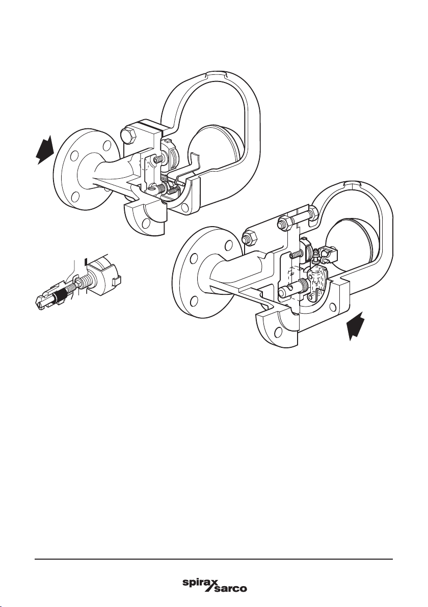
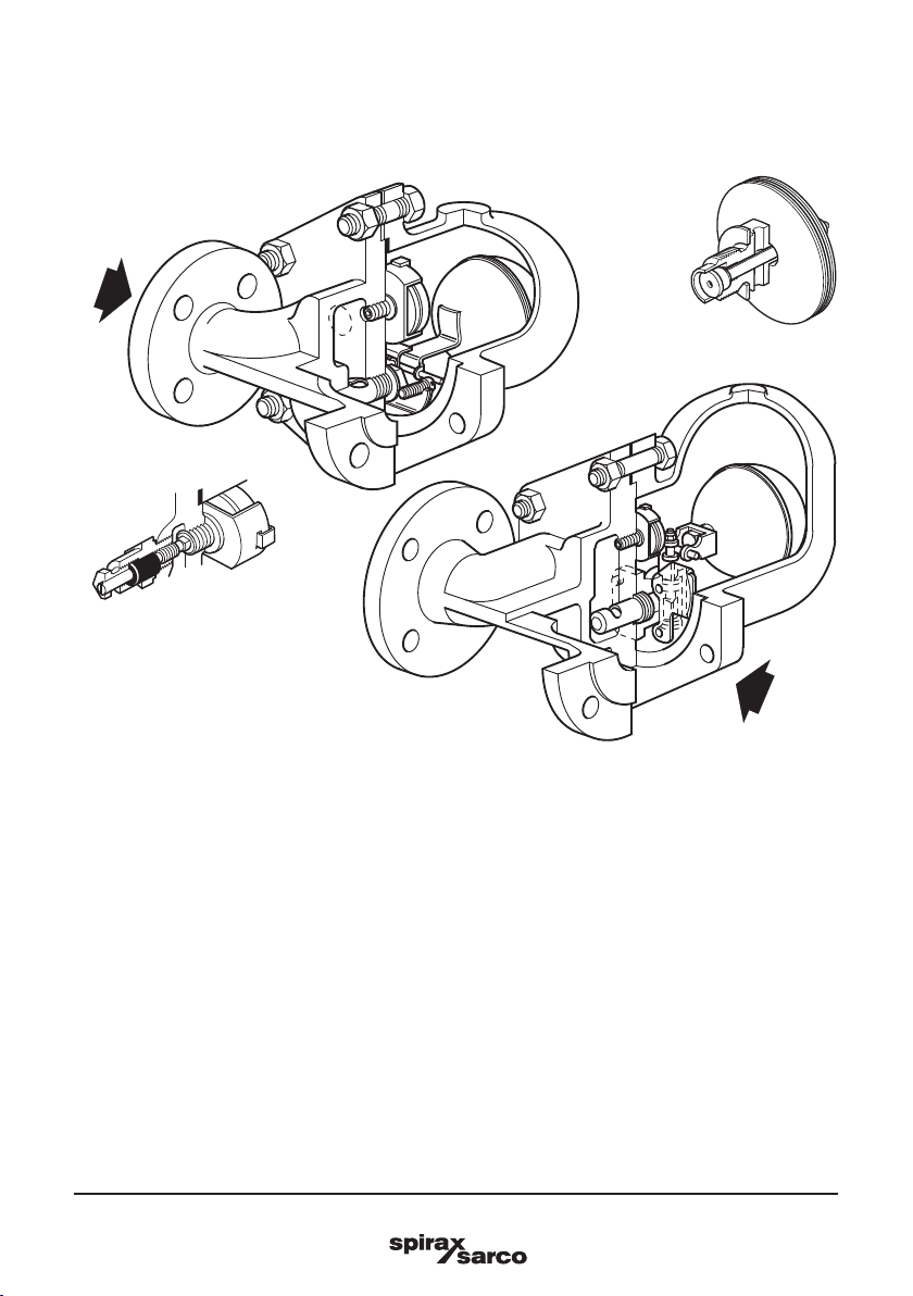
2.1 General description
The FT43 - cast iron, FT4 4 - carbon steel, FT46 - austenitic stainless steel and FT47 - SG iron ball float
steam traps have stainless steel working internals and automatic built-in air venting facility. These traps are
supplied with integrally flanged connections (for horizontal or vertical installations) and can be maintained
without disturbing the pipework. Please be aware that the flow direction is not the same for all FT trap types
or sizes but will be clearly marked on the trap body. For vertically orientated traps, identified by the added
'V' on the nomenclature i.e. FT44V, the flow is downwards only. The body and cover castings for the FT44,
FT46 and FT47 are produced by a TÜV approved foundry.
Air vent
The BP99/32 capsule which is used in 4.5 bar - 21 bar ball float steam traps is suitable for use on 150 °C
superheat @ 0 bar g. This value reduces with elevated pressure.
The bimetallic element is fitted as standard to the 32 bar variants to provide additional superheat
resistance. It is also available on other variants on request. Please refer to the pressure/temperature
graphs in the following pages.
Optional extras
A manually adjustable needle valve (designated 'C' on the nomenclature i.e. FT46- C) can be fitted to
these traps. This option provides a steam lock release (SLR) feature in addition to the standard air vent.
Note: The steam lock release and bimetallic air vent cannot be used in conjunction with each other.
Alternative arrangements may be available. For further information please contact Spirax Sarco.
The top of the cover can be drilled and tapped 3/8" BSP or NPT for the purpose of fitting a balance line
if requested at the point of order.
The bottom of the cover can be drilled and tapped 3/8" BSP or NPT for the purpose of fitting a drain
cock if requested at the point of order.
Standards
This product fully complies with the requirements of the EU Pressure Equipment Directive/UK Pressure
Equipment (Safety) Regulations and carries the mark when so required.
Certification
This product is available with a manufacturers’ Typical Test Report. Certification to EN 10204 3.1 can
be supplied at extra cost for the FT44 , FT46 and the FT47.
Note: All certification / inspection requirements must be stated at the time of order placement.
Note: For further product data see the following sections and Technical Information Sheets:
Product Material Section TI reference + Capacities
FT43
DN25 - DN50 Cast iron Section 2.2 TI-S02-21
DN80 - DN100 Cast iron Section 2.2 TI-S02-22
FT44
DN15 - DN50 Carbon steel Section 2.3 TI-S02-14
DN80 - DN100 Carbon steel Section 2.3 TI-S02-23
FT46 DN15 - DN50 Stainless steel Section 2.4 TI-P143-01
FT47 DN15 - DN50 SG iron Section 2.5 TI-P142-01 and TI-S02-36
2. General product information

IM-S02-30 CMGT Issue 14
8
FT43, FT44, FT46 and FT47 Ball Float Steam Traps
2.2 FT43 - Cast iron
Fig. 1
Sizes and pipe connections
DN25, DN40 and DN50
Note: Flow direction, for FT43 horizontal orientated traps, when facing the body:
- DN25 is left to right. (R-L versions are available for DN25 FT43TV PN16 only)
- DN40 and DN50 is right to left.
Flow direction, for FT43V vertically orientated traps is downwards only.
* Note: Only the one size, DN25, is available with JIS/KS flange connections with flow vertically downward
FT43V.
Standard flanges are EN 1092 PN16 with face-to-face dimensions in accordance with EN 26554 (Series 1).
On request - ASME B 16.1 Class 125 and JIS/KS 10 flanges are also available.
Note: ASME and JIS/KS flanges are supplied with tapped holes to receive flange bolts. ASME flanges have
UNC threads and JIS/KS have metric threads.
FT43 DN40 and DN50
FT43 DN25
FT4 3- C

IM-S02-30 CMGT Issue 14 9
FT43, FT44, FT46 and FT47 Ball Float Steam Traps
Pressure bar g
DB
A
C
Steam saturation curve
The product must not be used in this region.
A - BFlanged EN 1092 PN16.
A - CFlanged ASME 125.
A - DFlanged JIS/KS 10 *
Body design conditions PN16
PMA Maximum allowable pressure 16 bar g @ 120 °C (232 psi g @ 248 °F)
TMA Maximum allowable temperature 220 °C @ 12.1 bar g (428 °F @ 175 psi g)
Minimum allowable temperature 0°C (32 °F)
PMO Maximum operating pressure for saturated
steam service 13 bar g @ 195 °C (188 psi g @ 383 °F)
Note: The DN40 and DN50 traps are limited to a PMO equal to DPMX
TMO Maximum operating temperature 220 °C @ 12.1 bar g (428 °F @ 175 psi g)
Minimum operating temperature 0°C (32 °F)
Note: For lower operating temperatures consult Spirax Sarco
DPMX Maximum differential pressure
FT4 3- 4 .5 4.5 bar (65 psi)
FT43-10 10 bar (145 psi)
FT43-14 13 bar (188 psi)
Designed for a maximum cold hydraulic test pressure of: 24 bar g (348 psi g)
Note: With internals fitted, test pressure must not exceed DPMX
Pressure/temperature limits
Temperature °C
Pressure psi g
Temperature °F

IM-S02-30 CMGT Issue 14
10
FT43, FT44, FT46 and FT47 Ball Float Steam Traps
2.3 FT44 - Carbon steel
Sizes and pipe connections
DN15, DN20, DN25, DN40 and DN50
Horizontal traps:
Note the flow direction when facing the body is as follows:
- DN15 to DN25 is left to right.
- DN40 and DN50 is right to left.
Standard flanges are EN 1092 PN40 with face-to-face dimensions in accordance with EN 26554 (Series 1).
On request - ASME B 16.5 Class 150 and 300 and JIS/KS 20 flanges are also available with extended
face-to-face dimensions.
Vertical traps:
Note that the flow direction is vertically downwards only.
Standard flanges are EN 1092 PN40 with face-to-face dimensions in accordance with EN 26554 (Series 1).
On request - ASME B 16.5 Class 150 and 300 and JIS/KS 20 are also available with face-to-face dimensions
in accordance with EN 26554 (Series 1).
Note: ASME and JIS/KS flanges are supplied with tapped holes to receive flange bolts.
ASME flanges have UNC threads and JIS/KS have metric threads.
Fig. 2
FT4 4 DN40 and DN50
DN50 shown
FT4 4 DN15, DN20 and DN25
DN15 shown
FT4 4 - C
FT4 4
32 bar

IM-S02-30 CMGT Issue 14 11
FT43, FT44, FT46 and FT47 Ball Float Steam Traps
Pressure bar g
Temperature °C
D
A
The product must not be used in this region.
This product should not be used in this region as damage to the internals may occur.
A - BFlanged EN 1092 PN40 and ASME 300.
A - CFlanged JIS/KS 20.
A - DFlanged ASME 150.
Body design conditions PN40
PMA Maximum allowable pressure 40 bar g @ 100 °C (580 psi g @ 212 °F)
TMA Maximum allowable temperature 300 °C @ 27.5 bar g (572 °F @ 399 psi g)
Minimum allowable temperature -10 °C (14 °F)
PMO Maximum operating pressure for
saturated steam service 32 bar g @ 239 °C (464 psi g @ 462 °F)
Note: The DN40 and DN50 traps are limited to a PMO equal to DPMX
TMO Maximum operating temperature 285 °C @ 28.5 bar g (545 °F @ 413 psi g)
Minimum operating temperature 0°C (32 °F)
Note: For lower operating temperatures consult Spirax Sarco
DPMX
Maximum
differential
pressure
Size DN15, DN20, DN25 DN40, DN50
FT4 4- 4 .5 4.5 bar 4.5 bar (65 psi)
FT44-10 10 bar 10 bar (145 psi)
FT44-14 14 bar -(203 psi)
FT44-21 21 bar 21 bar (304 psi)
FT44-32 32 bar 32 bar (464 psi)
Designed for a maximum cold hydraulic test pressure: 60 bar g (870 psi g)
Note: With internals fitted, test pressure must not exceed DPMX
Caution: The trap in its complete operational form must not be subjected to a pressure greater than
48 bar otherwise damage to the internal mechanism may result.
C B
Pressure psi g
Temperature °F
Pressure/temperature limits
Steam saturation curve

IM-S02-30 CMGT Issue 14
12
FT43, FT44, FT46 and FT47 Ball Float Steam Traps
2.4 FT46 - Stainless steel
Sizing and pipe connections
DN15, DN20, DN25, DN40 and DN50.
Note: Flow direction when facing the body is as follows:
- DN15 to DN25 is left to right.
- DN40 and DN50 is right to left.
Standard flanges are EN 1092 PN40 with face-to-face dimensions in accordance with EN 26554 (Series 1).
On request - ASME B 16.5 Class 150 and 300 flanges are also available with face-to-face dimensions in
accordance with EN 26554 (Series 1).
Note: ASME flanges are supplied with tapped (UNC) holes for flange bolts.
Fig. 3
FT46
4.5 bar - 21 bar
DN15, DN20 and DN25
DN15 shown
FT46
4.5, 10 and 21 bar
DN40 and DN50
DN50 shown
FT46-C
4.5-21 bar
FT46
DN15 to DN50
32 bar

IM-S02-30 CMGT Issue 14 13
FT43, FT44, FT46 and FT47 Ball Float Steam Traps
Pressure/temperature limits
The product must not be used in this region.
This product should not be used in this region as damage to the air vent may occur.
A - BFlanged EN 1092 PN40 and ASME (ANSI) 300.
A - CFlanged ASME (ANSI) 150.
Note: The use of the bimetallic element extends the superheat resistance to in excess of 400 °C.
Body design conditions PN40
PMA Maximum allowable pressure 40 bar g @ 100 °C (580 psi g @ 212 °F)
TMA Maximum allowable temperature 400 °C @ 27.4 bar g (752 °F @ 397 psi g)
Minimum allowable temperature -10 °C (14 °F)
PMO Maximum operating pressure for saturated steam
service 32 bar g @ 239 °C (464 psi g @ 462 °F)
TMO
Maximum
operating
temperature
When fitted with a capsule 285 °C @ 30 bar g (545 °F @ 439 psi g)
When fitted with a bimetallic air
vent 400 °C @ 27.4 bar g (752 °F @ 397 psi g)
Minimum operating temperature
Note: For lower operating temperatures consult Spirax Sarco 0°C (32 °F)
PMX Maximum differential pressure
Size
DN15
DN20
DN25
DN40
DN50
FT46-4.5 4.5 bar 4.5 bar (65 psi)
FT46-10 10 bar 10 bar (145 psi)
FT46-14 14 bar - (203 psi)
FT46-21 21 bar 21 bar (304 psi)
FT46-32 32 bar 32 bar (464 psi)
Designed for a maximum cold hydraulic test pressure: 60 bar g (870 psi g)
Note: With internals fitted, test pressure must not exceed: 48 bar g (696 psi g)
Caution: The trap in its complete operational form must not be subjected to a pressure greater than 48 bar
otherwise damage to the internal mechanism may result.
Pressure bar g
Temperature °C
B
A
C
Pressure psi g
Temperature °F
Steam saturation
curve

IM-S02-30 CMGT Issue 14
14
FT43, FT44, FT46 and FT47 Ball Float Steam Traps
Sizing and pipe connections
DN15, DN20, DN25, DN40 and DN50.
Note: Flow direction, for horizontal orientated traps, when facing the body is as follows:
-DN15 to DN25 is left to right.
-DN40 and DN50 is right to left.
For vertically orientated traps the flow is downwards only.
Standard flanges are EN 1092 PN40 and PN25 with face-to-face dimensions in accordance with EN 26554
(Series 1).
On request - ASME B 16.5 Class 150 flanges are also available with face-to-face dimensions in accordance
with EN 26554 (Series 1).
Note: ASME flanges are supplied with tapped (UNC) holes for flanged bolts.
2.5 FT47 - SG iron
Fig. 4
FT47 DN40 and DN50
DN50 shown
FT47 DN15, DN20 and DN25
DN15 shown
FT47- C
FT47
32 bar

IM-S02-30 CMGT Issue 14 15
FT43, FT44, FT46 and FT47 Ball Float Steam Traps
FT47 DN40 and DN50
DN50 shown
Pressure/temperature limits
Pressure psi g
Temperature °F
Pressure bar g
Temperature °C
C
A
The product must not be used in this region.
This product should not be used in this region as damage to the internals may occur.
A - BFlanged EN 1092 PN25/40.
A - CFlanged ASME 150.
Body design conditions PN40
PMA Maximum allowable pressure 40 bar g @ 100 °C (580 psi g @ 212 °F)
TMA Maximum allowable temperature 300 °C @ 28 bar g (572 °F @ 406 psi g)
Minimum allowable temperature -10 °C (14 °F)
PMO Maximum operating pressure for saturated
steam service 32 bar g @ 239 °C (464 psi g @ 462 °F)
Note: The DN40 and DN50 traps are limited to a PMO equal to ∆PMX
TMO Maximum operating temperature 285 °C @ 29 bar g (545 °F @ 420 psi g)
Minimum operating temperature 0°C (32 °F)
Note: For lower operating temperatures consult Spirax Sarco
DPMX
Maximum
differential
pressure
Size DN15, DN20, DN25 DN40, DN50
FT47- 4 .5 4.5 bar 4.5 bar (65 psi)
FT47-10 10 bar 10 bar (145 psi)
FT47-14 14 bar -(203 psi)
FT47-21 21 bar 21 bar (304 psi)
FT47- 32 32 bar 25.5 bar (464 psi)
Designed for a maximum cold hydraulic test pressure: 60 bar g (870 psi g)
Note: With internals fitted, test pressure must not exceed PMX
Caution: The trap in its complete operational form must not be subjected to a pressure greater than 48 bar
otherwise damage to the internal mechanism may result.
B
Steam saturation
curve

IM-S02-30 CMGT Issue 14
16
FT43, FT44, FT46 and FT47 Ball Float Steam Traps
Note: Before actioning any installation observe the 'Safety information' in Section 1.
Warning
Note 1: The FT must be installed with the direction of flow as indicated on the body.
Ensuring the float arm is in the horizontal plane so that it rises and falls vertically.
Note 2: It’s recommended that a strainer is fitted upstream of the trap and that sound engineering
practice is followed and that the system undergoes regular maintenance to ensure the steam
quality is to industry standard.
Note 3: The installation of the trap needs to be carried having selected nuts, bolts and gaskets to
adhere to Industry Standards.
The nuts and bolts should be tightened to the required torque cited in the Industry Standard.
Referring to the Installation and Maintenance Instructions, name-plate, and Technical Information Sheet,
check that the product is suitable for its intended use.
3.1 Check materials, pressure and temperature and their maximum values. If the maximum operating limit
of the product is lower than that of the system in which it is being fitted, ensure that a safety device
is included in the system to prevent overpressurisation.
3.2 Determine the correct installation situation and direction of fluid flow – please be aware that the
flow direction is not the same for all FT trap types or sizes. However the flow direction will be clearly
marked on the trap body.
3.3 Remove protection covers from all connections and protective lm from all name-plates, where
appropriate, before installation on steam or other high temperature applications.
3. Installation
Fig. 5
The nameplate
indicates which way
is down

IM-S02-30 CMGT Issue 14 17
FT43, FT44, FT46 and FT47 Ball Float Steam Traps
FT
Fig. 6
3.4 The trap must be fitted with the float arm in a horizontal plane so that it rises and falls vertically. Note:
The trap can be visually checked for its correct orientation by reading the writing on the body, cover,
and name-plate. If installed correctly the writing will be seen to be displayed the correct way up.
3.5 The trap should be fitted below the outlet of the steam system, with a small drop leg immediately
proceeding the trap, typically 150 mm (6") see Figure 6. If no drop leg is allowed for then it may be
possible (under low load conditions) for steam to flow over the condensate in the bottom of the pipe
and reach the trap.

IM-S02-30 CMGT Issue 14
18
FT43, FT44, FT46 and FT47 Ball Float Steam Traps
3.7 If the trap is to be situated in an exposed position, it should be either lagged or drained by a separate
small thermostatic trap such as the Spirax Sarco No.8, or Bydrain.
3.8 Always fit a non-return (check) valve downstream of any steam trap which discharges into condensate
return lines where back pressure is experienced. This is not commonly caused by a rising condensate
line. The check valve will prevent the steam space flooding when the inlet pressure is reduced or the
steam is shut off.
Fig. 7
Slow speed cylinder
drainage with system unit
Air vent
Float
trap
Sight glass
Condensate out
Strainer
Air bottle
Cylinder
3.6 Float traps should be fitted as close to the outlet of the plant to be drained as possible otherwise
the trap can steam lock. Steam locking occurs when the pipe between the condensate outlet and
the steam trap fills with steam and prevents condensate from reaching the trap. This can lead to the
system waterlogging which will affect plant efficiency. It is very similar to the air locking experienced
in water systems.
The most common application where steam locking is a risk is on rotating cylinders and other
applications where condensate is removed via a dip tube or siphon pipe. Steam locking can easily
be prevented by fitting the trap with a combined thermostatic air vent and an adjustable needle valve
(SLR), Figure 7 shows an FT-C trap fitted on a slow speed cylinder.
The adjustable needle valve (SLR) is opened by turning the spindle anticlockwise. The standard factory
setting is ½turn which equates to an approximate steam 'bypass' of 22 kg/h @ 10 bar.
Site adjustment of the adjustable needle valve can be achieved by turning anticlockwise to increase
the bypass flow, and clockwise to reduce the flow.
When draining from a high speed cylinder application, there is need for large amounts of blow-through
steam to assist the flow of condensate out of the cylinder via the siphon tube.
In such cases the adjustable needle valve cannot handle such large amounts and an external bypass
with an adjustable needle valve is required. See Figure 8.

IM-S02-30 CMGT Issue 14 19
FT43, FT44, FT46 and FT47 Ball Float Steam Traps
Fig. 8
High speed cylinder with float trap
and parallel blow-through valve
Rotating cylinder
Float trap with
external bypass
Steam in
Rotary joint with
flexible couplings
Condensate
out
After installation or maintenance ensure that the system is fully functioning. Carry out tests on any alarms
or protective devices.
The float trap is a continuous trap, removing condensate the instant it forms. On start-up, the thermostatic
air vent allows air to bypass the main valve preventing the system air binding. Hot condensate will close the
air vent tightly, but as soon as it enters the main chamber of the trap, the float rises and the lever mechanism
attached to it opens the main valve - keeping the system drained of condensate at all times. When the steam
arrives, the float drops and closes the main valve. Float traps are renown for their high start-up load handling
capability, clean tight shut-off and resistance to waterhammer and vibration.
4. Commissioning
5. Operation
3.9 Ensure adequate space is left to
remove the cover from the body
for maintenance – the maximum
withdrawal to remove the cover is
200 mm (8").
Note:
If the trap is to discharge to atmosphere
ensure it is to a safe place, the discharging
fluid may be at a temperature of 100 °C
(212 °F).

IM-S02-30 CMGT Issue 14
20
FT43, FT44, FT46 and FT47 Ball Float Steam Traps
6.1 FT43, FT44, FT46 and FT47 (DN15 to DN50)
Dowel
Steam lock
release assembly
19 + 21
2
23
20
Warning
The cover gasket contains a thin stainless steel support ring which may cause physical injury
if not handled and disposed of carefully.
6. Maintenance and spare parts
18 17
Bimetallic air vent assembly
This manual suits for next models
3
Table of contents
Other Spirax Sarco Plumbing Product manuals
Popular Plumbing Product manuals by other brands

Hans Grohe
Hans Grohe Finoris 76445 Series Instructions for use/assembly instructions

LK Armatur
LK Armatur Tmax 422 quick start guide

Axor
Axor iBox universal 13587000 Assembly instructions

Sussex
Sussex SCALA installation guide

MEFE
MEFE CAT 679178 installation manual

Parker
Parker EO2-FORM Assembly instructions

Jacuzzi
Jacuzzi MOOD S installation manual

Burda
Burda Tronic U-03 installation guide

Lefroy Brooks
Lefroy Brooks M1-4301 Installation, operating, & maintenance instructions

Hans Grohe
Hans Grohe Cento XXL 2jet 14806000 Instructions for use/assembly instructions

Agua
Agua MONACO quick start guide

Kohler
Kohler K-6228 Installation and care guide