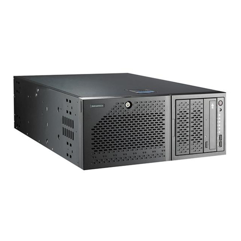
Spirent communications SPT-N11U User manual

SPT-N11U and SPT-N12U Installation Instructions |1
P/N 71-008728 Rev A, August 2019
SPT-N11U and SPT-N12U Chassis
Installation Instructions
This document is intended to guide you to a safe and successful installation of the Spirent
SPT-N11U or SPT-N12U mainframe chassis.
In this document...
• Certifications and Standards . . . . 4
• Introduction . . . . 7
• Site Selection . . . . 7
• Technical Specifications . . . . 8
• Powering the System . . . . 15
•RackMountingtheSPT-N11U/SPT-N12U . . . . 10
• Related Documentation . . . . 17
• How to Contact Us . . . . 18

SPT-N11U and SPT-N12U Chassis Installation Instructions
2|SPT-N11U and SPT-N12U Installation Instructions P/N 71-008728 Rev A, August 2019
Copyright
© 2019 Spirent Communications, Inc. All Rights Reserved.
All of the company names and/or brand names and/or product names referred to in this
document, in particular, the name “Spirent” and its logo device, are either registered
trademarks or trademarks of Spirent plc and its subsidiaries, pending registration in
accordance with relevant national laws. All other registered trademarks or trademarks are
the property of their respective owners. The information contained in this document is
subject to change without notice and does not represent a commitment on the part of
Spirent Communications. The information in this document is believed to be accurate and
reliable, however, Spirent Communications assumes no responsibility or liability for any
errors or inaccuracies that may appear in the document.
Limited Warranty
Spirent Communications, Inc. (“Spirent”) warrants that its Products will conform to the
description on the face of order, that it will convey good title thereto, and that the Product
will be delivered free from any lawful security interest or other lien or encumbrance.
Spirent further warrants to Customer that hardware which it supplies and the tangible
media on which it supplies software will be free from significant defects in materials and
workmanship for a period of twelve (12) months, except as otherwise noted, from the date
of delivery (the “Hardware Warranty Period”), under normal use and conditions.
To the extent the Product is or contains software (“Software”), Spirent also warrants that,
if properly used by Customer in accordance with the Software License Agreement, the
Software which it supplies will operate in material conformity with the specifications
supplied by Spirent for such Software for a period of ninety (90) days from the date of
delivery (the “Software Warranty Period”). The “Product Warranty Period” shall mean the
Hardware Warranty Period or the Software Warranty Period, as applicable. Spirent does
not warrant that the functions contained in the Software will meet a specific requirement
or that the operation will be uninterrupted or error free. Spirent shall have no warranty
obligations whatsoever with respect to any Software which has been modified in any
manner by Customer or any third party.
Defective Products and Software under warranty shall be, at Spirent's discretion, repaired
or replaced or a credit issued to Customer's account for an amount equal to the price paid
for such Product provided that: (a) such Product is returned to Spirent after first obtaining
a return authorization number and shipping instructions, freight prepaid, to Spirent's
location in the United States; (b) Customer provides a written explanation of the defect or
Software failure claimed by Customer; and (c) the claimed defect actually exists and was
not caused by neglect, accident, misuse, improper installation, improper repair, fire, flood,
lightning, power surges, earthquake, or alteration. Spirent will ship repaired Products to
Customer, freight prepaid, based on reasonable best efforts after the receipt of defective
Products. Except as otherwise stated, any claim on account of defective materials or for
any other cause whatsoever will conclusively be deemed waived by Customer unless
written notice thereof is given to Spirent within the Warranty Period. Spirent reserves the
right to change the warranty and service policy set forth above at any time, after
reasonable notice and without liability to Customer.

SPT-N11U and SPT-N12U Chassis Installation Instructions
SPT-N11U and SPT-N12U Installation Instructions |3
P/N 71-008728 Rev A, August 2019
TO THE EXTENT PERMITTED BY APPLICABLE LAW, ALL IMPLIED
WARRANTIES, INCLUDING BUT NOT LIMITED TO IMPLIED WARRANTIES OF
MERCHANTABILITY, NONINFRINGEMENT AND FITNESS FOR A PARTICULAR
PURPOSE, ARE HEREBY EXCLUDED, AND THE LIABILITY OF SPIRENT, IF
ANY, FOR DAMAGE RELATING TO ANY ALLEGEDLY DEFECTIVE PRODUCT
SHALL BE LIMITED TO THE ACTUAL PRICE PAID BY THE CUSTOMER FOR
SUCH PRODUCT. THE PROVISIONS SET FORTH ABOVE STATE SPIRENT'S
ENTIRE RESPONSIBILITY AND CUSTOMER'S SOLE AND EXCLUSIVE REMEDY
WITH RESPECT TO ANY BREACH OF ANY WARRANTY.
Safety Precautions
Warning: Calls attention to operating procedures or practices that should be followed to
avoid bodily injury or damage to equipment.
Caution: Reflects conditions that could cause product damage or data loss.
Note: Describes limitations on the use of the equipment or procedure.
Equipment Noise Level
Warning: The SPT-N11U/SPT-N12U is designed for operation in an unattended room
(e.g., datacom or telecom equipment room). The system can generate noise levels up to
90.7 dB (A-weighted sound power level, LWA as measured per ISO 3741 Sound Power
Noise Measurement), and appropriate ear protection should be worn when working in
proximity to the chassis. Please contact your employer or local health and safety agencies
for specific guidelines for your working environment.
No User-Serviceable Parts
Warning: No user-serviceable parts inside. Do not open.
Waarschuwing: Er zijn geen door de gebruiker te vervangen onderdelen. Niet openen.
Attention: Aucune pièce se trouvant à l'intérieur ne peut être réparée ou remplacée par
l'utilisateur. Ne pas ouvrir.
Calibration
At the time of manufacture, all components manufactured by Spirent Communications are
calibrated in accordance with applicable procedures. Spirent Communications equipment
is calibrated using national standards, consensus standards, and ratio-type measurements
based on self-calibration techniques. By design, the equipment has no user adjustments
and does not require further calibration. Products are calibrated within the published
environmental specifications for the products. At the time of shipment, this Spirent
Communications product met its published operating specifications.
Unpacking
Before opening the product carton, examine it for damage. If damage is not visible,
unpack the carton and check contents for damage. Save all packing materials. If damage is

SPT-N11U and SPT-N12U Chassis Installation Instructions
Certifications and Standards
4|SPT-N11U and SPT-N12U Installation Instructions P/N 71-008728 Rev A, August 2019
noted, forward an immediate request to the delivering carrier to perform an inspection and
prepare a damage report. Save the container and packing material until contents are
verified or in case the equipment will be transported at a later date.
Report the nature and extent of damage to Spirent Communications Customer Support so
that action can be initiated to repair or replace damaged items or instructions can be
provided for returning items.
The responsibility of the manufacturer ends with delivery to the first carrier. All claims for
loss, damage, or nondelivery must be made against the delivering carrier within
10 calendar days of receipt of shipment.
Important: The SPT-N11U/SPT-N12U weighs over 100 lbs and will require at least four
people to move and install it. The preferred method is to install it using an IT equipment
lift designed for heavy network equipment.
Open the packaging carefully and save all packaging materials. Safely shipping the SPT-
N11U/SPT-N12U requires the use of the included pallet, custom-fit foam, and shipping
box. Set these materials aside for future use. Set aside the accessories and power supplies.
These will be needed later. Carefully lift the chassis out of the box using the side and front
handles and securely place it on a level and stable surface.
Damaged or Missing Equipment
If any equipment is damaged or missing, call (800) 774-7368 or (818) 676-2616
(international) for technical support. Registered users may also access the Spirent
Communications support website at https://support.spirent.com. You may also email
Certifications and Standards
FCC
The SPT-N11U/SPT-N12U chassis complies with the limits for a Class A digital device in
accordance with Part 15 of the FCC Rules. These limits are designed to provide
reasonable protection against harmful interference when this equipment is operated in a
commercial environment. Operation is subject to the following two conditions:
•This device may not cause harmful interference.
•This device must accept any interference received, including interference that may
cause undesired operation.
This device generates, uses, and can radiate radio frequency energy if not installed and
used in accordance with the instructions in this manual. Operating this equipment in a
residential area is likely to cause harmful interference, and the customer will be required
to rectify the interference at his or her own expense. This product requires the use of
external shielded cables to maintain compliance pursuant to Part 15 of the FCC Rules.

SPT-N11U and SPT-N12U Chassis Installation Instructions
Certifications and Standards
SPT-N11U and SPT-N12U Installation Instructions |5
P/N 71-008728 Rev A, August 2019
CE
The CE symbol on the product label (on the back of the box) indicates this network
appliance is compliant with the EMC Directive and Low Voltage Directive of the
European Union. This product meets the following technical standards:
•EN 55022 — “Limits and Methods of Measurement of Radio Interference
Characteristics of Information Technology Equipment.”
•EN 55024 — “Limits and methods of measurement of immunity characteristics for
information technology equipment.”
•EN 60950 — “Safety of Information Technology Equipment.”
TUV
This product carries the cTUVus mark.
Key Points of cTUVus Certification:
•The cTUVus mark is accredited by OSHA (NRTL) for the U.S. and SCC for Canada.
•The cTUVus mark is recognized as equivalent to the UL and CSA marks by city,
county and state/provincial regulators throughout the U.S. and Canada.
•Safety testing conducted to applicable U.S. and Canadian standards and in most cases
can be combined with testing for other countries.

SPT-N11U and SPT-N12U Chassis Installation Instructions
Certifications and Standards
6|SPT-N11U and SPT-N12U Installation Instructions P/N 71-008728 Rev A, August 2019
Environmental Considerations
This label is on all Spirent-provided electrical and electronic products that are sold and
shipped.
This label indicates that the product contains material that presents an environmental
concern. Spirent encourages users of Spirent-provided electrical and electronic equipment
to not dispose of the labeled products in waste collection units where the waste is destined
for landfills. Electrical and electronic equipment should be collected separately and
recycled, reused, and processed for recovery and waste treatment in accordance with your
local, regional, and federal laws. If you have any questions regarding this labeling, please
contact your Spirent Communications representative.

SPT-N11U and SPT-N12U Chassis Installation Instructions
Introduction
SPT-N11U and SPT-N12U Installation Instructions |7
P/N 71-008728 Rev A, August 2019
Introduction
The Spirent SPT-N11U/SPT-N12U mainframe chassis is the foundation for Spirent's new
series of test modules. By optimizing the packaging and through the use of the latest
technology, the SPT-N11U/SPT-N12U is designed to lower the cost of testing high-scale
Internet networks and devices.
With its efficient architecture, the SPT-N11U/SPT-N12U supports a variety of
environments from multi-user functional testing to multi-chassis switch fabric and core-
router stress testing.
Site Selection
The Spirent SPT-N11U/SPT-N12U is a high-end network testing device that must be
installed in a dust free and dry environment with adequate airflow, power, and cooling.
•The SPT-N11U/SPT-N12U is designed with front to rear airflow and both ventilation
locations must remain unobstructed for proper operation. Inadequate cooling or
airflow can result in an over-temperature situation that will cause an automatic system
shut-down.
•The inlet air temperature must be in the range of 59° to 95° F (15° to 35° C); 20% to
80% relative humidity
•The SPT-N11U/SPT-N12U is designed to be mounted in a Telecom-style 19" 2- or 4-
post open rack.
• SPT-N11U chassis occupies 11 rack units, SPT-N12U occupies 12 rack units
• The rack must be designed, and adequately secured, to accommodate the fully
loaded weight of the chassis and any other installed equipment.
–SPT-N11U is approximately 232 lb.
–SPT-N12U is approximately 234 lb.
• It is not recommended to install the chassis in an enclosure unless it is specifically
designed to handle the airflow and cooling requirements of the chassis.
•Depending on your ordered configuration, a fully loaded chassis requires seven (7)
115V 15A circuits, or four (4) 230V 15A circuits, with no other connected equipment
and each with its own breaker. See the section on power requirements (page 8) for
more information.

SPT-N11U and SPT-N12U Chassis Installation Instructions
Technical Specifications
8|SPT-N11U and SPT-N12U Installation Instructions P/N 71-008728 Rev A, August 2019
Technical Specifications
•Environmental
• Operating requirements: 59° to 95° F (15° to 35° C); 20% to 80% relative
humidity
• Heat dissipation: SPT-N11U 24,000 BTUs/hr, SPT-N12U 28,000 BTUs/hr
(assumes 80% heat load for air conditioning)
• Sound power level: up to 90.7 dB LWA
Warning: Use appropriate ear protection when working in proximity to an operating
chassis.
•Chassis Design and Form Factor
• EIA 19" rack compatible, 11RU or 12 RU high, front or mid-rack mounting
• 12 test module slots
• Front and side-front to back airflow
• Field replaceable fan trays, system controller, system hard drive, and power
supplies
•Physical
• SPT-N11U:
–Dimensions: 17.5"W x 19.25"H x 33.3"D (44.45 cm x 48.9 cm x 84.6 cm).
30" (76.2 cm) depth measured from front mounting flange
–Installation and shipping weight: 125 lb. (58.6 kg) (3 system and 2 slot PSUs
and fans installed, no test modules installed)
–Approximate weight fully loaded: 232 lb. (105.2 kg)
• SPT-N12U:
–Dimensions: 17.5"W x 21"H x 33.3"D (44.45 cm x 53.34 cm x 84.6 cm).
30" (76.2 cm) depth measured from front mounting flange
–Installation and shipping weight: 127 lb. (57.7 kg) (3 system and 2 slot PSUs
and fans installed, no test modules installed)
–Approximate weight fully loaded: 234 lb. (106.1 kg)
•Power
• Inlet AC for STC-N11U-110: 7 x 115V @ 15A, or 7 x 230V @ 6A; one 15A
circuit dedicated for system operation and one 15A circuit per two test module
slots
• Inlet AC for STC-N11U-220: 4 x 230V @ 15A; one 15A circuit dedicated for
system operation and one 15A circuit per four (4) test module slots
• Peak power requirement: 7kW for fully loaded SPT-N11U, 8.2kW for SPT-N12U
•Administration and Operation
• Up to 32 simultaneous users per chassis
• IPv4 and IPv6 admin network compatible

SPT-N11U and SPT-N12U Chassis Installation Instructions
Technical Specifications
SPT-N11U and SPT-N12U Installation Instructions |9
P/N 71-008728 Rev A, August 2019
• Built-in AndroidTM touchscreen (SPT-N11U only)
• SSH terminal emulation via Ethernet
• Direct via external video connector and USB ports
•Indicators and controls
• System power on/off
• Controller reset
• Built-in LCD touchscreen (SPT-N11U)
• Built-in LCD display (SPT-N12U)
• Front panel LEDs:
–Temperature, fan, admin link, system and system power status
–Test module slot power status
• Rear panel LEDs:
–Admin Ethernet link, speed and activity
–Chassis synchronization Master/Slave and status
•Connectors
• Front panel: 4 x USB 2.0 (keyboard or mouse)
•Rear panel:
–DVI-I video (console)
–2 x USB 2.0 (keyboard or mouse)
–1 PPS and 10 MHz BNCs and DB9 serial DCE (for ETR support)
–10/100/1000M BASE-T RJ-45 Ethernet (admin)
–1588v2 Ethernet (supported on Rev. B controllers only)
–Synch in/out RJ-45 (chassis synch chain)
–System hard drive access panel

SPT-N11U and SPT-N12U Chassis Installation Instructions
Rack Mounting the SPT-N11U/SPT-N12U
10 |SPT-N11U and SPT-N12U Installation Instructions P/N 71-008728 Rev A, August 2019
Rack Mounting the SPT-N11U/SPT-N12U
This section describes the procedure for installing the chassis in an EIA 19" two-post or
four-post equipment rack. The following tools and equipment are required for installing
the equipment:
•#2 Phillips-head screwdriver
•Eight (8) equipment rack screws and nuts (if required) for your chosen rack
•ACC-2021A 4-Post Rack Mount Tray or rack shelf at least 30" deep and capable of
handling a static load of at least 350 lb for each chassis (for four-post rack mounting)
The chassis is shipped standard with a front mounting flange for four-post racks and a
mid-mount flange for two-post racks.
Due to the weight of the system, the power supplies should be installed after properly
securing the chassis. Refer to SPT-N11U/SPT-N12U Chassis Power Supply Installation
Instructions.
Warning: An empty SPT-N11U system weighs approximately 125 lb. An empty SPT-
N12U system weighs approximately 127 lb.
Spirent recommends that an IT equipment lift be used to rack the system. If one is not
available, the system should be lifted by four people onto a secured shelf capable of
handling a static load of at least 350 lb for each chassis, where it can then be secured
safely using the rack screws. The chassis should be completely empty of modules and
power supplies when being moved.

SPT-N11U and SPT-N12U Chassis Installation Instructions
Rack Mounting the SPT-N11U/SPT-N12U
SPT-N11U and SPT-N12U Installation Instructions |11
P/N 71-008728 Rev A, August 2019
Two-Post Rack Mounting
Warning: The chassis should never be installed in a two-post rack using the front rack
ears. There is a risk of equipment damage and personal injury, due to the weight of the
system.
1Attach the center-mount brackets with the supplied screws if they are not already
secured to the chassis. Be sure to use all screws (Figure 1).
Figure 1. Location of Center-mount Brackets
2Lift the chassis into the rack using an equipment lift or with four people to support
and secure the chassis (Figure 2).
Figure 2. Using an Equipment Lift for Installation

SPT-N11U and SPT-N12U Chassis Installation Instructions
Rack Mounting the SPT-N11U/SPT-N12U
12 |SPT-N11U and SPT-N12U Installation Instructions P/N 71-008728 Rev A, August 2019
3With the chassis being supported in the intended installation location, install four (4)
rack mount screws through each rack ear and into the rack; totaling eight (8) rack
mount screws (Figure 3).
Figure 3. Securing the Center-Mount Brackets
With the chassis secured, you can install the power supplies. Refer to SPT-N11U Chassis
Power Supply Installation Instructions.
Approximate locations of 4
rack mount screws to be
used on each side of the
chassis.

SPT-N11U and SPT-N12U Chassis Installation Instructions
Rack Mounting the SPT-N11U/SPT-N12U
SPT-N11U and SPT-N12U Installation Instructions |13
P/N 71-008728 Rev A, August 2019
Four-Post Rack Mounting
1Remove the center-mount brackets with a screwdriver if they are secured to the
chassis (Figure 4).
Figure 4. Remove the Center-Mount Brackets
2Install the ACC-2021A tray or a shelf with a depth of at least 30" and with a static
loading capacity of at least 350 lb per chassis (Figure 5).
Figure 5. Shelf Installed for Four-Post Rack Mounting
3Lift the chassis onto the shelf using an equipment lift or with four people to support
and secure the chassis (Figure 6 on page 14).

SPT-N11U and SPT-N12U Chassis Installation Instructions
Rack Mounting the SPT-N11U/SPT-N12U
14 |SPT-N11U and SPT-N12U Installation Instructions P/N 71-008728 Rev A, August 2019
Figure 6. Using an Equipment Lift for Installation

SPT-N11U and SPT-N12U Chassis Installation Instructions
Powering the System
SPT-N11U and SPT-N12U Installation Instructions |15
P/N 71-008728 Rev A, August 2019
4With the chassis being supported in the intended installation location, install a
minimum of four (4) (recommended 8) rack mount screws through each front rack ear
and into the rack (Figure 7).
Figure 7. Securing the Front-Mount Brackets to a Four-Post Shelf
5With the chassis secured, you can install the power supplies. Refer to SPT-N11U
Chassis Power Supply Installation Instructions.
Powering the System
Important: Each power cord must be connected to a 15A circuit with no other connected
equipment and each with its own breaker. Installation of this chassis must comply with
local and national electrical codes. If necessary, consult with the appropriate agencies to
ensure compliance.
The Spirent SPT-N11U/SPT-N12U mainframe requires multiple circuits that require 100-
120 VAC or 200-240 VAC, 50 or 60 Hz, and 15A. These circuits are used to power fifteen
(15) power supplies (three system and twelve slot power supplies). The number of circuits
and voltage varies by system type:
•SPT-N11U/SPT-N12U-220: Four (4) 200-240 VAC, 50 or 60 Hz, and 15A
•SPT-N11U/SPT-N12U-110: Seven (7) 100-120 VAC, 50 or 60 Hz, and 15A; or, Seven
(7) 200-240 VAC, 50 or 60 Hz, and 6A.
Minimum 4 screw locations
shown here (recommended
8 locations are shown in
Figure 3 on page 12).

SPT-N11U and SPT-N12U Chassis Installation Instructions
Powering the System
16 |SPT-N11U and SPT-N12U Installation Instructions P/N 71-008728 Rev A, August 2019
Note: The SPT-N11U/SPT-N12U does not support redundant power supply
configurations.
Each of the power inputs are used to power specific areas of the system and are labeled
accordingly (Figure 8). For the SPT-N11U/SPT-N12U-110 configuration, the rightmost
power socket is for the system (the system controller and fans); moving to the left, the
next socket powers module slots 1 and 2, then 3 and 4, etc., with the leftmost socket
powering slots 11 and 12.
Figure 8. Power Supply Sockets for SPT-N11U/SPT-N12U-110 Configuration
For the SPT-N11U/SPT-N12U-220 configuration, the rightmost power socket is also for
the system (the system controller and fans); moving to the left, the next socket powers
module slots 1 - 4, then 5 - 8, etc., with the leftmost socket powering slots 9 - 12.
For either chassis configuration, if all the slots for a particular power socket are not in use,
the socket does not have to be powered. The status of the slot power is indicated by the
LEDs on the front panel above each slot. Please refer to the Spirent TestCenter Hardware
Reference for information about the LEDs. The system power socket must always be
powered to run any of the module slots.
Note: 2-slot cards require both occupied slots to be powered.
The power sockets are a C20 type, and your system ships with the appropriate number of
C19 power cables that fit into the C20 receptor for the configuration and region of
intended use. You must use these cables. Optionally, for connection to a PDU with the
appropriate number and sized circuits, ACC-2020A C20 to C19 power cords can be used.
Powers the System
Controller and Fans
Six (6) Labeled Power Sockets for Module Slots

SPT-N11U and SPT-N12U Chassis Installation Instructions
Related Documentation
SPT-N11U and SPT-N12U Installation Instructions |17
P/N 71-008728 Rev A, August 2019
To insert the power cables:
1Slide out the power cord retaining clip located above the socket.
2Angle the retaining clip up and plug the power cord into the socket.
3Slide the retaining clip to the location appropriate for your cord.
4Push the retaining clip down over the cable.
The unit is now ready to be powered on and set up for operation. Refer to Getting Started
with Spirent TestCenter for information on operating your chassis for the first time.
Related Documentation
•SPT-N11U/SPT-N12U Chassis Power Supply Installation Instructions – Describes the
procedure to install and remove power supplies
•Getting Started with Spirent TestCenter – Provides hardware set up, software
installation, licensing, and software upgrade and downgrade instructions.
•Using the ACC-2017 Hypermetrics Single-slot Card Carrier – Describes the
procedure for installing and removing test modules that require card carriers for use in
the SPT-N11U, SPT-N12U, and SPT-N4U chassis.
•Using the ACC-2018 Hypermetrics Dual-slot Card Carrier – Describes the procedure
for installing and removing test modules that require card carriers for use in the SPT-
N11U, SPT-N12U, and SPT-N4U chassis.
•SPT-N11U and SPT-N12U Fan Tray Replacement Instructions – Describes the
procedure to replace the fan tray.
•Spirent Hardware Reference – Describes Spirent chassis, modules, and accessories.
Information is provided on module LEDs, multiple chassis connections, cables, and
chassis commands. Basic information is provided on system administration functions
and diagnostics.
•Release Notes – Contain information that may affect product installation, test
configuration, or test results, including last-minute requirements or product changes.
It is highly recommended that you review all Release Notes before you install or use
the SPT-N11U/SPT-N12U chassis.
Spirent Customer Service Center
The Spirent Customer Service Center (https://support.spirent.com) includes a powerful
Knowledge Base. The Knowledge Base offers an easy-to-use browse mode and an
intelligent search. Log in with your user ID and password to gain access to additional
content that is available only to customers - user manuals, help files, release notes,
technical bulletins, and more. When you log in, you also gain access to software and
firmware downloads.

SPT-N11U and SPT-N12U Chassis Installation Instructions
How to Contact Us
18 |SPT-N11U and SPT-N12U Installation Instructions P/N 71-008728 Rev A, August 2019
How to Contact Us
To obtain technical support for any Spirent Communications product, please contact our
Support Services department using any of the following methods:
Americas
E-mail: support@spirent.com
Web: https://support.spirent.com
Toll Free: +1 800-SPIRENT (+1 800-774-7368) (North America)
Phone: +1 818-676-2616
Hours: Monday through Friday, 05:00 to 17:00, Pacific Time
Europe, Middle East, Africa
E-mail: support@spirent.com
Web: https://support.spirent.com
Phone: +33 (1) 6137 2270 (France)
Phone: +44 1803 546333 (UK)
Hours: Monday through Thursday, 09:00 to 18:00, Friday, 09:00 to 17:00, Paris Time
Asia Pacific
E-mail: support@spirent.com
Web: https://support.spirent.com
Phone: +86 (400) 810-9529 (toll-free mainland China only)
Phone: +86 (10) 8233 0033 (China)
Hours: Monday through Friday, 09:00 to 18:00, Beijing Time
Information about Spirent Communications and its products and services can be found on
the main company website at https://www.spirent.com.
Company Address
Spirent Communications, Inc.
27349 Agoura Road
Calabasas, CA 91301
USA
© 2019 Spirent Communications, Inc. All Rights Reserved.
This manual suits for next models
1
Table of contents
Other Spirent communications Chassis manuals