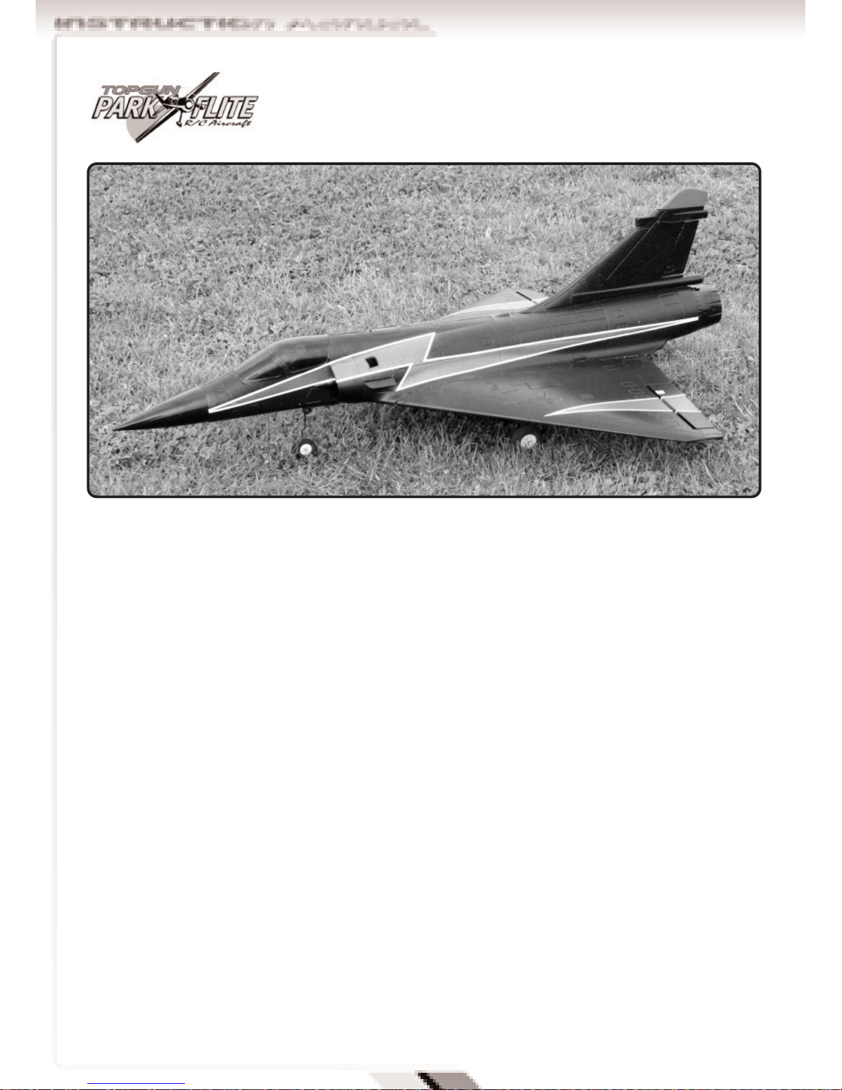
Park Flite Mirage 2000 User manual


2
Mirage 2000
RTF Model
INSTRUCTION MANUAL
Top Gun Park Flite are proud to present this high
performance ducted fan sport scale model of the
Mirage 2000 We feel that this model emulates the
style, performance and character of its full size
counterpart.
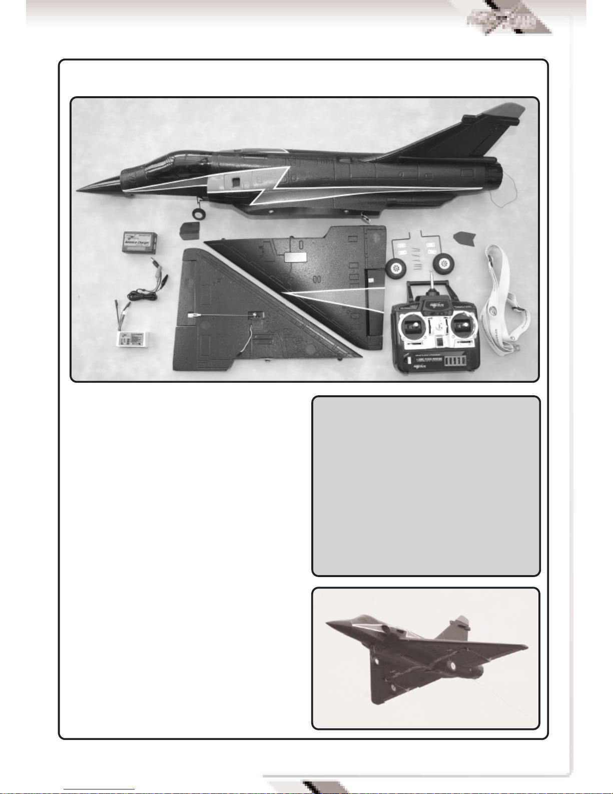
Supplied as a Ready to Fly package with transmitter,
LiPo flight battery and charger, ARTF or Airframe
only, this model has been designed with the utmost
care and attention to detail to produce a light
weight, strong, and realistic looking model
aeroplane with excellent flying characteristics.
This model is a high performance miniature aircraft
that allows intermediate to advanced model pilots to
perform both scale and aerobatic manoeuvers. The
light weight, large wing area and delta wing design
allow the model to fly both fast and slow, with high
speed rolls and tight turns while maintaining full
control.
These instructions assume a reasonable level of
competence for both building and flying and we
recommend that the model is flown at a recognised
club with frequency control measures and suitable
third party insurance.
The owner – pilot of this model should take note of
regulations, and local bylaws before flying this
aircraft.
Please take time to read through these instructions
before commencing assembly. We list operations in
order of works to reduce the risk of damage during
assembly.
Please read through the warnings before use.
A 11.1V 1300 mAh lithium polymer (LiPo) battery and
charger is included as part of this package and
these cells must be operated with care to prevent
the risk of fire.
LiPo Batteries are soft cased and can be easily
damaged by sharp items, puncturing of the soft
casing can cause fires and we recommend that they
are stored and handled carefully.
Use only a LiPo rated charger, set to a maximum of 3
cells (11.1v) and no more than 1 amp charge
current.
Remove battery from the aircraft and charge on a
non flammable, non conductive surface
Due to continual and ongoing product development
the parts shown in the manual may differ from those
supplied.
Congratulations on purchasing the Mirage 2000 RTF

3
Fuselage with ducted fan, motor, Electronic
Speed Control (ESC) receiver, rudder- steering
servo, pushrods and nose wheel.
Two delta wing panels with ailerons connected to
factory installed servos
Forward stabiliser canards (2 off)
Rear fin strake/ ECM Antennae
2 Main undercarriage assemblies with wheels
and mounting hardware
4 function fully proportional 35Mhz transmitter
Adjustable quick release neck strap for
transmitter
Tube of adhesive
LiPo Battery 3 cell 11.1V 1300 mAh (15c)
2- 3 cell balance type 800mAh LiPo charger and
12v power lead
KIT CONTENTS AND DESCRIPTION
SPECIFICATIONS
Wing span: 680mm (26.75”)
Length: 980mm (38.5”)
Wing Area: 13 Dm2(200 sq inches)
Weight: 565 g (20 Ounces)
Radio: 4 function 35Mhz PPM
3 Qty micro servos
25 Amp brushless ESC
Motor: Brushless in runner
5 blade ducted fan
11.1v 1300mAh LiPo battery

4
FUSELAGE ASSEMBLY.
Supplied complete and ready for use with ducted
fan unit using high performance brushless in
runner motor.
25Amp Electronic Speed Control (ESC) prewired to
motor with extended leads to forward battery box
and hinged cover.
Sprung steerable nose wheel assembly.
35mhz 8 channel receiver pre-wired to ESC and
rudder-steering servo with extension leads to each
wing.
Smoked canopy
over cockpit with
profile pilot.
Nose cone
supplied loose.
WING ASSEMBLY.
Supplied as two halves.
Each wing half includes undercarriage fixing plates
and hinged aileron control surfaces.
Wing mounted aileron servos connect to control
horn with pushrods and snap link clevis connector.
MAIN UNDERCARRIAGE ASSEMBLIES.
Two sets of lightweight wheels fixed onto wire
torque rod undercarriage.
Four clamp plates and 8 fixing screws for securing
to wing plates.
Steerable nose gear is pre fitted to fuselage.
Two forward canard surfaces for sides of intake
ducts.
One Fin strake / ECM antennae for mounting near
top of fin.

5
BATTERY AND CHARGER
11.1V (3 cell) 1300mAh (C) LiPo Battery rated at
15C max discharge.
12v DC input 0.8 A output balancing type fast
charger for 2 and 3 cell packs.
12v crocodile clip connecting lead
ADHESIVE
5ml tube of foam safe adhesive.
Note pierce end of tube with pin in screw on lid.
SECTION 2: BATTERY AND CHARGER
BATTERY AND CHARGER
The kit includes a high performance 11.1V (3 cell)
1300mAh LiPo Battery rated at 15C (19.5 amp) max
discharge.
This must be charged using the dedicated 12v DC
input 0.8 Amp output fast charger and connecting
lead
Connect the crocodile lead connectors to a 12V DC
power source (a 12V car battery is ideal), ensuring
that correct polarity is observed. Red is positive (+)
and Black is Negative (-).
Connect the lead into the matching socket of the
battery charger and the Red LED will illuminate.
WARNING:
A lithium polymer (LiPo) battery rated at 15C
(19.5A) discharge and fast charger is included as
part of this package, these cells must be
operated with care to prevent the risk of fire.
LiPo Batteries are soft cased and can be easily
damaged by sharp items, puncturing of the soft
casing can cause fires and we recommend that
they are stored and handled carefully.
Use only the supplied balance charger or a LiPo
rated charger set to a maximum of 3 cells (11.1v)
and less than 1 amp charge current.
Remove battery from the aircraft and charge on a
non flammable, non conductive surface

6
Push the white balance plug of the battery into the
matching charger output socket to commence
charging.
The green LED illuminates to confirm charging and
switches off when the charge is complete
A full charge will take between 1 and 2 hours.
TRANSMITTER
The RIR 4EXA is a fully proportional 4 function
35Mhz transmitter
The transmitter is supplied in a Mode 2
configuration. Mode 2 is also known as Throttle
Left.
The left stick controls Throttle and rudder
movement.
The right stick controls aileron and elevator
movement.
Battery state is indicated by a bank of coloured
LED’s. With green for full and red for empty.
As soon as the indicator changes to amber the
model should be landed to allow battery
replacement.
A red LED indicates dangerously low voltage. The
model should be landed immediately to replace
batteries before all control is lost.
Frequency control is by removable crystal, The
transmitter frequency is identified on the crystal
holder located on the front of the transmitter.
8 off AA size dry cells or high capacity Nimh
batteries must be inserted before operation.
Remove the rear cover and install batteries into the
battery tray as directed by the moulded in polarity
(+ & -) markings.
A small panel of five small slide switches is set on
the front panel of the transmitter.

7
Switches 1 to 4 are electronic servo reversing
switches and should be adjusted to give the correct
control surface deflections relative to stick
movements.
The mix switch activates a ch1-ch2 mix to give
elevon (2 servos both functioning as ailerons and
elevators) for delta winged aircraft
For the Mirage the switch must be in the ‘Mix’
position
SECTION 3: ASSEMBLY
Locate the wing halves and fuselage assembly
Remove the protective tape from the wings and
fuselage and dry fit the wings and fuselage
together.
Apply adhesive on one wing panel and the mating
fuselage. Press into position and use tape or bands
to hold in place.
Wipe off any excess adhesive and allow to dry.
Repeat the procedure to the other wing.
Apply adhesive to the remaining wing root and
fuselage side. Press wing into position and use tape
or bands to hold in place.
Wipe off any excess adhesive and allow to dry.
Connect the aileron servo leads to the extensions
located in the fuselage matching black to black and
white to white.
Tuck wires into slot and apply self adhesive tape
over slot.
Repeat on opposite wing panel
Locate the main undercarriage assemblies, clamp
plates and fixing screws.
Insert undercarriage into mounting plate and fix in
place with saddles and four self tapping screws.
Repeat on opposite wing panel

8
SECTION 3: ASSEMBLY CONTINUED
Locate the plastic nose cone and apply a bead of
adhesive to its inside edge.
Push onto the fuselage, wipe off excess adhesive
and allow to dry.
Locate the two plastic forward canards and
fuselage.
Use a sharp modelling knife to cut a narrow slot in
the side of the fuselage behind the air intake.
A moulded in line gives the position.
Apply adhesive to the canard and insert into the
slot.
Be sure to fit canard with its top face sloping down.
Locate the Fin strake / ECM antennae and
fuselage.
Use a sharp modelling knife to cut a narrow slot in
the side of the fin.
A moulded in line gives the position.
Apply adhesive to the middle of the Fin strake / ECM
antennae and insert into the slot.

9
Be sure to fit with pointed face forward.
Construction is now complete and the following
steps can be considered as part of the daily
assembly and rigging of the model.
SECTION 4: FINAL SET UP
Open the hinged battery bay door by turning the
catches.
Insert into the battery and ensure that battery and
ESC leads project out of the aperture.
Ensure that transmitter is switched on with throttle
down.
Connect the battery and ESC leads together Red-red
and Black-Black and close the battery cover using
the catches to lock it in place.
Uncoil the receiver aerial and fully extend to hang
off the rear of the aircraft.
Check that all controls operate in the correct
manner and that surfaces for elevons (Combined
aileron and elevator) are level.
Adjust surfaces if required by unclipping the
pushrod clevis connectors and winding in or out to
suit.
To adjust the rudder and nose wheel steering it is
necessary to remove the cover plate just behind the
cockpit.
Loosen the clamp connector before adjusting the
pushrod location.
With the trims and wheel central re-tighten the
clamp connector.
Move transmitter sticks to ensure free movement of
the control surfaces.
WARNING:
With the battery connected and the model
switched on the motor is now live. The
Electronic speed controller (ESC) will go through
its start up procedure and will emit a series of
beeps while it configures throttle positions. The
motor could start unexpectedly and we
recommend that the model is restrained during
handling.

10
CHECK THE BALANCE.
The model should sit level or slightly nose down
when supported upside down from a point 260 mm
from the wing trailing edge. This corresponds to a
point midway along the top surface air brakes panel
line.
DO NOT ATTEMPT TO FLY WITH A REARWARD
BALANCE POINT
SECTION 5: FIRST FLIGHT
BEFORE THE TEST FLIGHT
On completion of the model take time to test the
model in the workshop.
Switch on the transmitter, connect the battery and
double check that all surfaces operate in the correct
manner without stalled servos.
Check for adequate range with and without motor
running.
If everything is okay, take it to the flying field and
rig it up again.
Always follow the frequency control procedures of
your local flying site and ensure that you have
adequate third party insurance cover.
Repeat the full pre flight inspection before flying.
FLYING
The Mirage 2000 is capable of 5 to 10 minute flight
times and can R.O.G (Rise Off Ground) from smooth
metalled runways. A hand launch will be required If
flying from grass. It is aerobatic and able to
perform loops and rolls.
Due to its light weight it should not be flown in wind
greater than 10mph.
WARNING:
Do not advance the throttle unless the model is
restrained. With the powerful motor-fan
combination, the model will accelerate across a
smooth surface very quickly.
570 mm
CENTRE OF GRAVITY POINT

11
Control throws set during assembly will produce a
model capable of flying smooth scale like
performance and medium to high speed aerobatic
manoeuvers.
The control surface movements can be increased by
moving the clevis connectors nearer to the control
surfaces.
To reduce movements move the pushrod
connections nearer to the servo on the output arms
and further out along the control surfaces horns.
ENJOY YOURSELF BUT ALWAYS FLY SAFE!

12
TGP0180 Mirage 2000 EDF EP Fuselage
TGP0181 Mirage 2000 EDF EP Main Wing Set
TGP0182 Mirage 2000 EDF EP Nose, Canopy,
Plastic Covers
TGP0183 Mirage 2000 EDF EP Plastic Parts
TGP0184 Mirage 2000 EDF EP Front Landing Gear
TGP0185 Mirage 2000 EDF EP Landing Gear
TGP0186 Mirage 2000 EDF EP Ducted Fan
w/o Motor
TGP0535 TGPF Outrunner Motor (Mirage)
TGP0526 TGPF 1300mAh 12c 11.1v Lipo Battery
(Mirage)
TGE0001 Etronix 8.4G Micro Servo
TGE0051 Etronix 25A Brushless Speed Control
DISTRIBUTORS OF QUALITY MODEL & HOBBY PRODUCTS
Saxon House, Saxon Business Park, Hanbury Road, Bromsgrove, Worcestershire. B60 4AD. England
Tel: +44 (0) 1527 575349 Fax: + 44 (0) 1527 570536
E-mail: [email protected]
Web site: www.cmldistribution.co.uk
TOP GUN PARKFLITE MIRAGE 2000 SPARE PARTS LIST
Table of contents
Other Park Flite Toy manuals
Popular Toy manuals by other brands

Eduard
Eduard Mi-26 Halo exterior quick start guide

Fisher-Price
Fisher-Price X1464 instructions

NINCOAIR
NINCOAIR 265 ALUTWIN 2,4G Handbook

Mega Construx
Mega Construx DYG89 Assembly instructions

Mattel
Mattel Tyco RC Disney Pixar Toy Story N9119 Assembly instructions

MGA Entertainment
MGA Entertainment Bratz Featherageous manual

Modellbau Lindinger
Modellbau Lindinger A 18E instruction manual

Eduard
Eduard Zoom P-40B Tomahawk quick start guide

Faller
Faller RAINBOW MILLENIUM AMUSEMENT PARK RIDE manual

MODSTER
MODSTER Spit Fire MK II user manual

Fisher-Price
Fisher-Price W9758 manual

TA HORIZONS
TA HORIZONS MIGHTY EDGE 33 Assembly & instruction manual