Spirit Halloween Spirit Brackets Kit User manual

Introduction
Congratulations on purchasing the Spirit Brackets Kit that allows very secure attachment of an A.L.I.C.E. pack
frame to your Spirit Halloween Proton Pack.
The Spirit Brackets Kit is designed to work with the Spirit Halloween Deluxe Proton Pack and can be used with
the existing Spirit motherboard (cardboard, foam and fabric back side covering). Some minor cutting of the
cardboard motherboard and drilling of two mounting holes in the Proton pack and 3 mounting holes in the
A.L.I.C.E. frame is required for installation. All mounting hardware is included, but you must supply your own
Spirit Proton pack, A.L.I.C.E. frame and tools.
The brackets have been tested on the 2017 and 2018 versions of the Spirit Proton pack and also with two
separate A.L.I.C.E. frames:
1) Rothco Alice Pack Frame with Attachments
https://www.rothco.com/product/rothco-alice-pack-frame-with-attachments
2) Fox Outdoor Products LC-1 A.L.I.C.E. Field Pack Frame
https://www.foxoutdoor.com/ItemDetails.aspx?win=&cid=3&ccid=23&cscid=175
If you use some other A.L.I.C.E. frame, there could be fitment issues since the brackets are specifically sized to
work with the above two A.L.I.C.E. frames.
Here is the Spirit Pack with the frame attached:
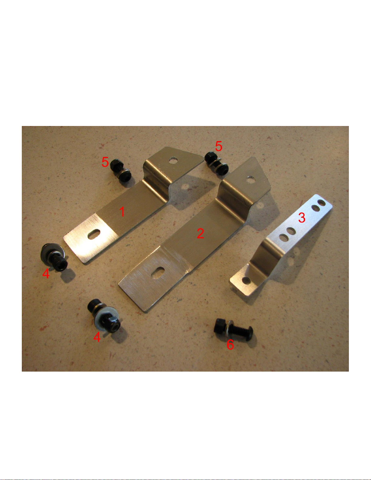
Spirit Brackets Kit Contents
Brackets:
1) Right hand side (facing the front of the pack) bumper bracket
2) Left hand side (facing the front of the pack) bumper bracket
3) Center replacement mounting bracket
Bolts:
4) 2x Socket Head Bolt for attachment to the bumper. (3/16” Hex Key, 10mm open end wrench)
5) 2x Button Head Bolt for attachment to the frame sides. (5/32” Hex Key, 10mm open end wrench)
6) Button Head Bolt for attachment to the frame center. (5/32” Hex Key, 10mm open end wrench)

Installation of main parts in the Spirit Pack
Getting started:
The first step is to remove the back of the Spirit Pack so we can access the inside of the pack shell.
Flip the pack over and we need to locate the screws that hold the fabric covered cardboard “motherboard” to the
back of the pack.
You have two main choices here, 1) remove the fabric to expose the cardboard and then glue the fabric back on
when done, or 2) make small cuts in the fabric above each screw and leave the fabric attached to the cardboard.
I liked option #2 as I expect to open up the pack again (for new wand and sound electronics, hint hint!)
Open the battery cover and then stick your hand between the cardboard and the fabric that is glued to the
cardboard around the edges. You can feel around and locate 4 of the 5 screws that are holding the cardboard to
the plastic pack.
When located, use the X-acto knife or razor blade to make a small cut in the fabric to expose the head of the
tiny Philips head screw. I could reach 4 of the screws, but the 5th I could not feel from inside, so pressed around
the material from above and located the screw. Knowing where they are would have helped, so here I pulled
the material around the screw and washer so you could easily see where you _should_ find these screws:
After re-installing the back cover, the screws can still be essentially hidden and only small cuts in the material
above them allow easy access for the next time you want access in to the pack.
The screws aren’t the only thing holding the cardboard onto the pack, and the cardboard is not very stiff, so
great care should be taken removing the cardboard backing from the pack. Near the straps, the loom and some
random spots along the edge, glue to hold those items of the fabric also oozed out enough to connect the
cardboard to something else in the pack. I used a flat screwdriver to carefully separate the cardboard and the
pack plastic, frame or loom while slightly lifting the cardboard. I worked my way all around the edge before
lifting the cardboard fully from the pack. I did not have any places in the middle of the pack have glue, it was
only around the outside edges.
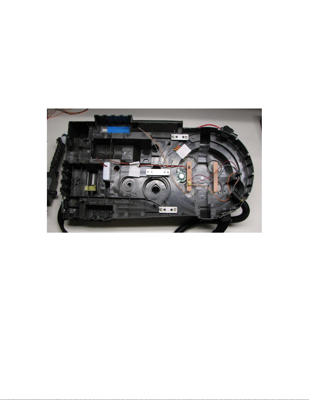
Once you get the back removed, here is the view inside the pack:
You can leave the screws in the cardboard or remove them and put them in the posts they come from so they
don’t get lost.

Replacing the center bracket:
There is a center structural bracket that needs to be replaced
with the center mounting bracket (item #3):
To replace the existing bracket, just remove the four screws and the bracket can be lifted out. Place the Spirit
Center bracket (item #3) over the 4 posts that the screws were removed from and screw in the four screws. The
bent portion of the new bracket should be pointing toward the top of the proton pack away from the Cyclotron
section.
The next step is to cut out a rectangular hole in the motherboard cardboard/foam/fabric to let the top piece of the
bracket be exposed. Just place the motherboard back on the pack and position it as it was before it was
removed. Press down around where the bracket interferes with the motherboard so you get an indent in the
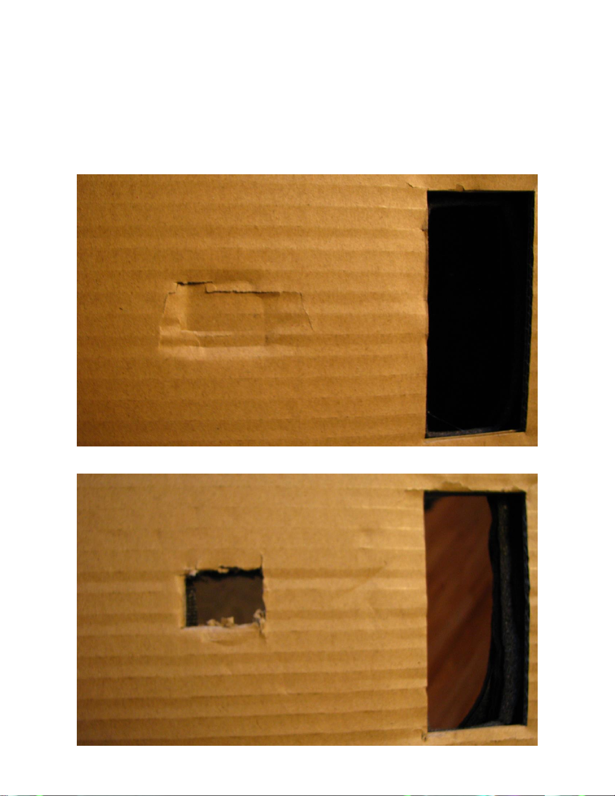
carboard and will have that show you exactly where to cut. I pushed a bit too hard trying to get a better picture
and dented the cardboard more than needed:
Then I used a razor blade to cut out the rectangular hole:
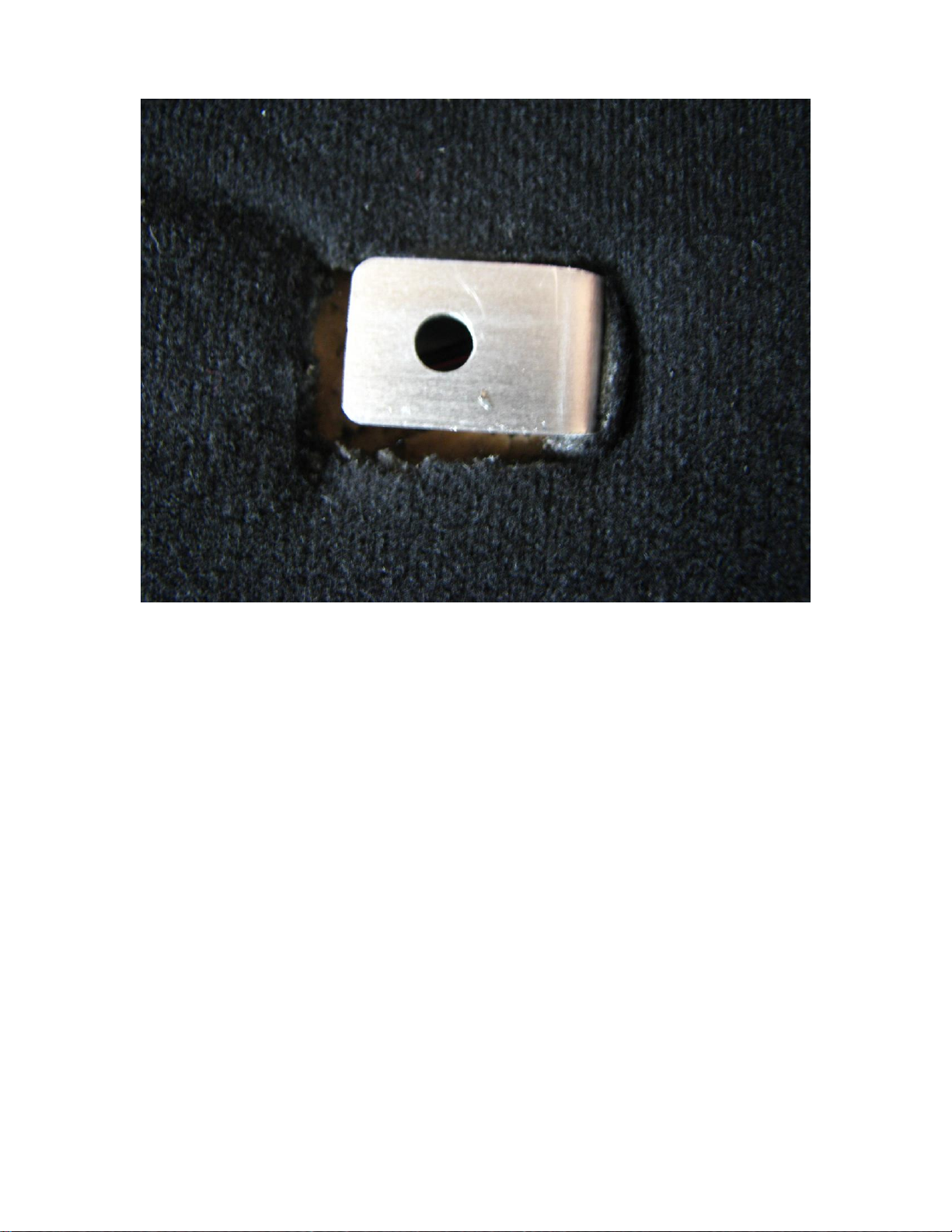
When the Motherboard is placed back on the Proton pack, the bracket should now be flush with fabric on the
motherboard:

Adding side brackets:
The two side brackets mount inside the bumper that goes across the center of the Cyclotron portion of the Spirit
Pack. There are already molded in plastic screw heads and we will use those to center the holes that need to be
drilled into the pack.
Use a 1/8”drill bit and drill a hole into the center of the screw heads (one on each side of the pack):
Before After
The hole we really need is a 15/64”hole, but it is easier for me to start with a smaller hole and make sure it is
centered before I drill the larger hole. If you are comfortable with just drilling the 15/64”hole that should also
be fine.
You may wish to grind down the fake screw head or can leave it as is. Even if you decide to grind down the
screw head, drill the holes first since once you grind it down it is harder to find where the center of the hole
should be drilled.

Here is a picture of the side after I ground down the screw head:
Finished look:
As shown above, use the Socket head bolts to mount the two side brackets (item #1 and #2) to the holes that you
just drilled with the Bolts #4. Hex head goes on the outside along with the smaller washer, through the pack,
through the slotted mounting bracket hole, then the larger washer and the locking nut. Do not completely
tighten the bolt so that the bracket can still be adjusted up and down. The bent portion of the brackets stick out
away from the pack.
After all of the brackets have been attached (the side brackets are still a bit loose) and the motherboard is still
off of the pack, it is time to test fit the A.L.I.C.E frame and then tighten the side brackets. Set the frame on the
pack by holding one side of the frame a few inches from the pack and making sure the other side slides into one
of the side brackets. Rotate the frame towards the pack on the other side and pull the unused side bracket
towards the center of the pack. This should give enough to allow the frame to snap into place.
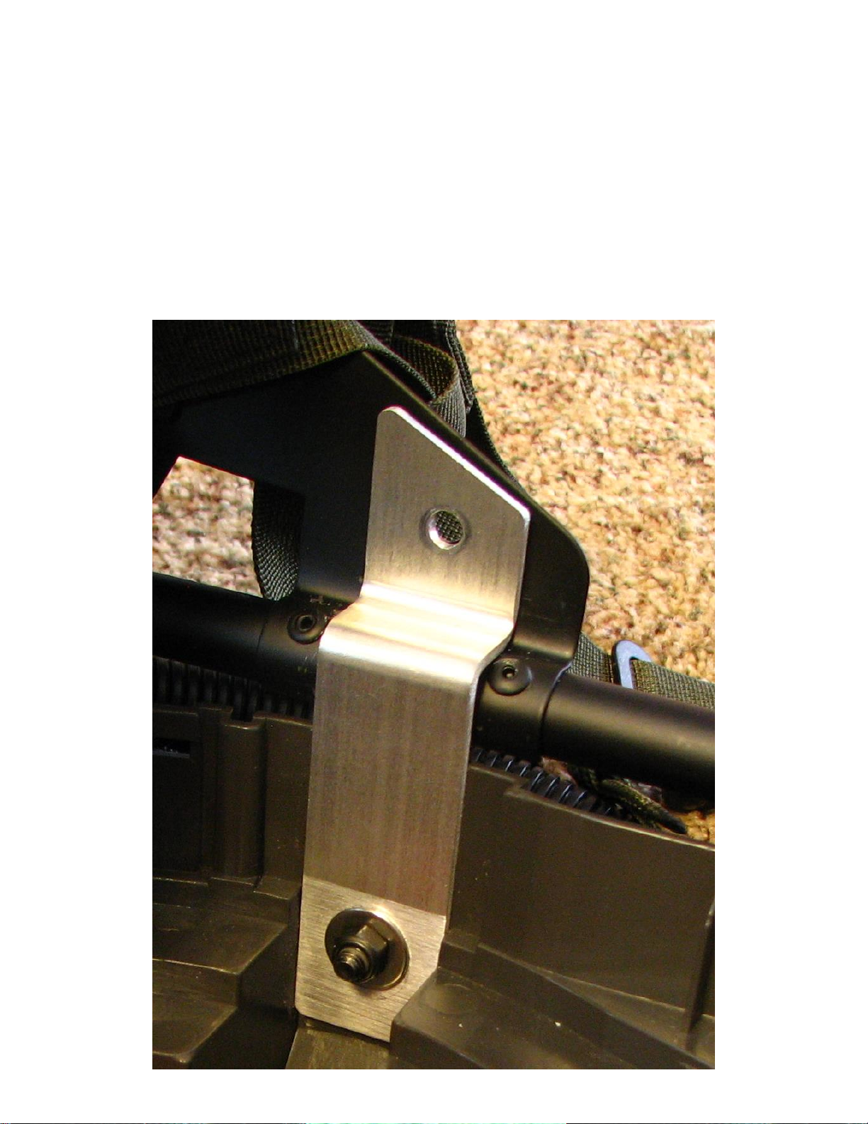
The side brackets should be centered between the rivets on the side braces of the A.L.I.C.E. frame:

Adjust the bracket so that it captures the frame tube without too much play. Make sure both sides are aligned
(and the center brace of the frame is over the center bracket that was added to the pack) and then tighten down
the two bolts (item #4) with a 3/16”hex key and a 10mm open end wrench (or socket).
Drilling the A.L.I.C.E frame:
The frame needs three 15/64”holes for the button head screws to go through to attach the frame to the newly
installed brackets.
Clamp the two side frames to the brackets while making sure the center brace was aligned with the raised
portion of the center bracket. Now mark the center hole (yes it is somewhat of a pain to do that) on the brace so
you can drill out the first hole. Use a center punch to make an indent and then use your 15/64”drill bit to drill
the hole. I drilled it on the pack and it made a mess of metal shavings so my next pack I drilled after I removed
the frame!
After the center hole is drilled, remount the frame and attach bolt #6 to hold the center of the frame in place
while you mark the two side holes to drill into the A.L.I.C.E. frame. I drilled through the bracket hole rather
than marking and drilling later and this worked fine and the shaving did not pile up inside the pack like with the
center bracket.
Finishing up:
Time to remove the old straps (I didn’t do this in the pictures –the old straps were still attached to the pack).
After the old straps are removed, remount the cardboard/foam/material motherboard with the five original
screws. Your pack should look like this:

I also left the five screws holding the motherboard to the pack visible for this picture. You will probably want
to move the material around so that they are very well hidden.
Time to place the frame on the pack. Same method as before: get one side in the bracket and then pull the other
bracket toward the middle of the pack to allow the frame to slide over the bracket and snap in place.
Now use the two Bolts #5 to attach the sides of the A.L.I.C.E frame (use a 5/32”hex key and 10mm wrench or
socket) and Bolt #6 (use a 5/32”hex key and a 10mm open ended wrench –not much else fits) to firmly attach
the frame to the brackets.
You do have to remove the frame to get access to the battery, but it is fairly quick and only requires removing
those three bolts.
Have fun!
Other Spirit Halloween Toy manuals


Popular Toy manuals by other brands

evolution models
evolution models FUSION3 instruction manual

4M
4M Bottle Catamaran Assembly instructions

LEGO
LEGO 10665 Juniors instructions

Hasbro
Hasbro Spiderman 3 Bump and Go Spiderman 4 Wheeler... instruction manual

Flex innovations
Flex innovations FV-31 Cypher instruction manual

REVELL
REVELL KIT 8341 Assembly manual

Horizon Hobby
Horizon Hobby Ultimate 2 instruction manual

Carrera RC
Carrera RC Power Wave?300001 Assembly and operating instructions

GREAT PLANES
GREAT PLANES Extra 300S ARF instruction manual

Lionel
Lionel Bay Window owner's manual

LEGO
LEGO LUDO 40198 manual

Martha Stewart
Martha Stewart G78102 Assembly and care instructions


