Spirit system Spirit User manual

User Guide
Version 1.0.22
1

CONTENTS
1. Safety
2. Introduction
3. Installation
4. Wiring
5. Configuration
6. First flight
7. Problems and solutions
8. Thanks
2

1. SAFETY
R/C models such as helicopters are not toys! It is necessary to check all
instructions of the manufacturer of the model, comply with local laws, carry
out preventive checking of the model and repair all deficiencies
immediately.
Rotor blades and propellers rotate at high speed and, if used incorrectly,
can lead to serious injury to persons or damage to the model.
If you encounter any problems, contact your model shop or experienced
modelers.
Especially, pay attention to your own safety and the safety of others. Never
fly among humans, or animals, or on private property without authorized
access.
Fly only in safe places where no additional damage is possible to other
objects, because the model can become unmanageable for various
reasons, such as failure of electronics or wear parts, pilot error or
interference.
Do not try to control crashed models nor repair the damaged parts, replace
them with new ones.
Never fly the model with vibrations, it may be even uncontrollable. Also,
flight characteristics can be much worse. Find the source of the vibrations
and fix the problem.
Spirit is not an autopilot, it is necessary to have knowledge of flying R/C
models. The system is only designed to improve flight performance.
We recommend using R/C simulators designed for training before the first
flight.
User takes full responsibility for any damage or injury, because the
manufacturer is not able to guarantee correct conditions in which the unit is
being used.
3

2. INTRODUCTION
Spirit is a device for stabilizing R/C models such as flybarless helicopters,
which features an electronic paddle simulation and a rudder gyro.
Thanks to flybarless mechanics, the system improves the efficiency and
maneuverability of the helicopter, while also extending flight time.
Flight characteristics are easily customizable according to your preference
from stable flight for beginners to demanding acrobatics with maximum
agility for experts.
Because the Spirit uses the most advanced technology, the model can be
controlled very precisely even under harsh conditions such as strong wind
while maintaining a constant pirouette.
This user guide will help you to properly mount the unit on a model and carry
out configurations step by step to prepare it for the first flight. It is very
important to carefully adjust everything to make your flight as pleasant as
possible.
Please check our website spirit-system.com for downloading new firmware
and software updates.
You can also raise your questions in our forum.
4
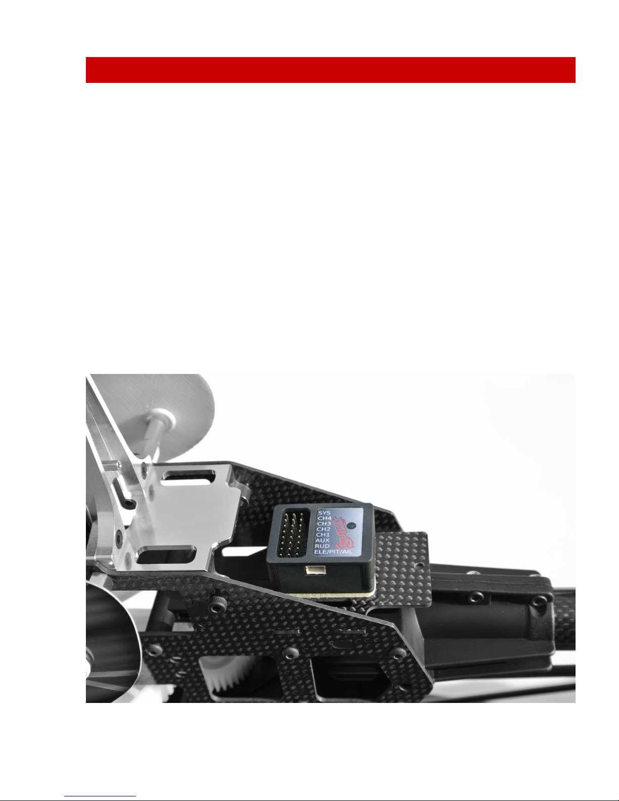
3. INSTALLATION
The mounting of Spirit plays an important role for the correct operation of
your model.
Find a suitable location where vibration is as low as possible - that location is
usually given by the manufacturer for mounting the gyro.
A very significant factor is that the unit should be positioned exactly
perpendicular to each rotational axis.
The unit can be mounted in two different positions. Depending on your
preferences it can be:
Horizontal
The unit is attached to its lower part so the connectors face upwards. It can
be rotated by 180°in yaw axis so that the connectors can be closer to the
front or rear of the model.
The unit is always positioned parallel to the longitudinal axis of the model.
5

Vertical
The unit is located on the side so the connectors are also at one of the sides.
It can be rotated by 180°in yaw axis so that the connectors can be closer to
the front or rear of the model.
The unit is always parallel to the longitudinal axis of the model.
In order to better avoid vibrations on the model, it is necessary to choose the
right double-sided tape. It should prevent the transmission of vibrations from
the model, which are undesirable for the unit.
Vibrations may be not only created by incorrectly balanced blades or
propellers, but also by damaged bearings, bent shafts and other
mechanical issues.
6

4. WIRING
Wiring to the unit depends on the type of used receiver.
Spirit can be connected as a standalone tail gyro or flybarless system.
WARNING
Spirit is pre-programmed to 1520us servo neutral impulse and 50 Hz
frequency – get servo parameters from the manufacturer.
If the neutral impulse is different such as 760us, do not connect this servo yet,
it could be destroyed!
Some connectors have non-standard dimensions. They could interfere with
neighboring positions after plugging in the unit. As a solution, we
recommend to replace it for JR or Futaba connector.
Never plug a connector for powering the unit to SYS or ELE/PIT/AIL positions!
4.1. STANDALONE GYRO
Owners of a flybared helicopter can take advantage of the head-lock gyro,
which keeps the tail in the direction given by the transmitter irrespective of
effects from wind or any unwanted forces.
It is required to connect rudder servo into position CH4 of Spirit unit.
In case you use a standard receiver, you will need to connect GEAR (or AUX)
from receiver with AUX position on the unit.
Secondly, connect cable from receiver position RUD to position RUD on the
unit.
4.2. FLYBARLESS
Owners of a flybarless helicopter can take advantage of the head-lock gyro
and also cyclic stabilization. This will stabilize the model in all axes; moreover,
it should be less prone to wind, extend flight time and make the model more
agile.
Flight characteristics should be more pleasant which allows the pilot to carry
out even the most challenging maneuvers.
7

Rotor blades are directly linked to the cyclic servos, so demands for servos
are significantly higher. They should be faster and stronger to respond as
quickly as possible to any change.
Even flybarless rotor blades are different in some aspects. For better flight
characteristics it is recommended to use them.
In case you intend to use Spirit as flybarless system all servos should be
connected in the corresponding positions:
CH1 (aileron), CH2 (elevator), CH3 (aileron/pitch), CH4 (rudder).
For standard receivers it is necessary to use two normal and one special
cable. Three connectors should be plugged into the receiver and the end of
this cable to the unit.
4.3. CONNECTION OF STANDARD RECEIVER (PWM)
The unit is powered by two cables from the receiver connected to AUX and
RUD positions.
Never plug a connector for powering the unit to SYS or ELE/PIT/AIL positions!
8
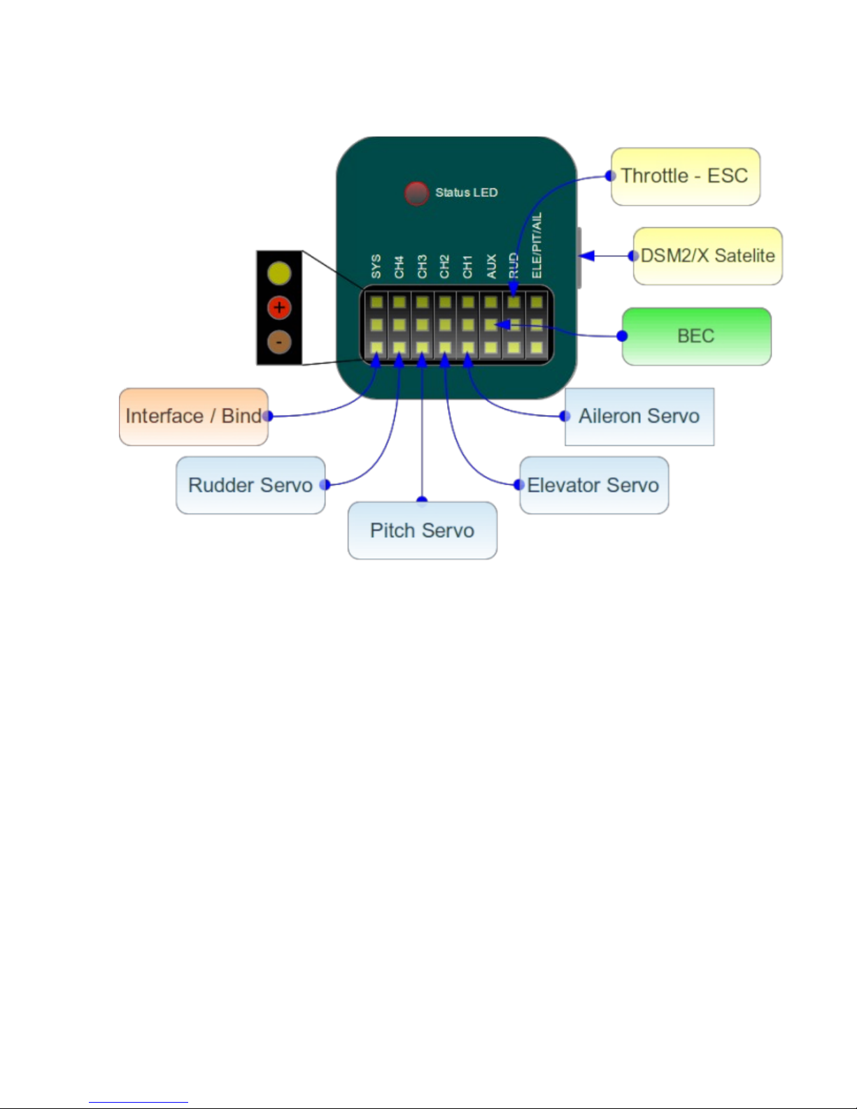
4.4. CONNECTION OF SPEKTRUM DSM2/X SATELLITE
Connection to BEC is optional. In case that the model is powered by an
external power supply (other than internal BEC) BEC must be connected to
AUX position.
Never plug a connector for powering the unit to SYS or ELE/PIT/AIL positions!
9
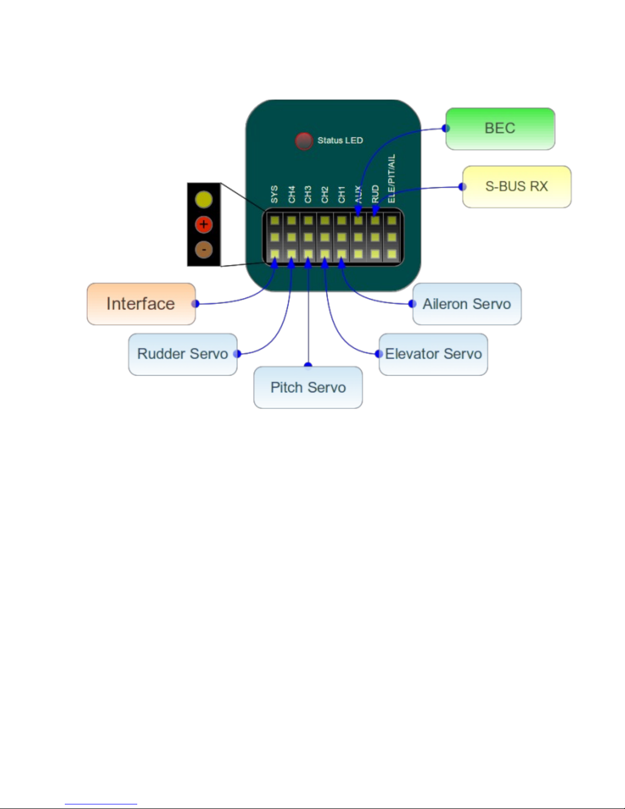
4.5. CONNECTION OF FUTABA S-BUS RECEIVER
WARNING
When using S-BUS it is necessary to have an INVERTER which can be
purchased separately. Inverter replaces cable between receiver and unit in
RUD position.
Connection to BEC is optional. For models of class 500 and larger it is
recommended to use dual power supply cables due to increased power
consumption. That means besides the inverter, additional power supply
cable should be connected to AUX position.
Never plug a connector for powering the unit to SYS or ELE/PIT/AIL positions!
4.6. UNIT
All cables connected to the unit must be oriented so that the signal wire
(orange) is closer to the connector pin labels, respectively to center of the
unit.
10

5. CONFIGURATION
Configuration is one of the next important steps for correct operation of the
system.
Configuration is performed using the software, which combines efficiency
and simplicity, while offering a set of adjustable parameters, including
advanced options.
5.1. CONNECTION WITH PC
Before you begin the actual configuration it is necessary to connect the
system to a computer.
This connection allows so-called USB interface comprising a serial converter
and interface cable.
Depending on the operating system a driver must be installed after
connecting the converter to USB port.
In case a driver is installed successfully a new virtual COM port should be
visible in the software and device manager.
MS WINDOWS
Install a driver from software installer. This process will be described in
following section.
APPLE MAC OS X
Download and install a driver from following URL:
http://spirit-system.com/dl/driver/SiLabsUSBDriverDisk.dmg
GNU/LINUX
Nothing has to be installed.
11

5.2. CONNECTION WITH UNIT
If you already have attached a USB interface to your computer, it is
necessary to also connect the interface cable to SYS position in Spirit.
To establish a connection, connect a battery to the model first. To power the
unit a BEC, battery, or receiver's power supply can be used.
Mostly RUD and AUX connector pins are used to power the unit.
The middle wire must be positive voltage potential of the voltage supply, so-
called Plus (3 – 15V voltage range supported).
WARNING
If the unit is not configured yet (e.g. new unit) it is advised to not connect a
servo.
5.3. CONFIGURATION SOFTWARE INSTALLATION
Software is capable of running on MS Windows, Apple Mac OS X, GNU/Linux
and Android platforms. If it is not installed yet, you can download it from the
Spirit web site:
spirit-system.com .
Please download software for your platform, then you should proceed with
following guidelines.
MS WINDOWS
Start the downloaded software – installer and go through wizard.
If the driver is not installed yet, please select it in installer to be installed.
Installer should go through all necessary steps to state that your computer is
prepared for the first start of the configuration software. Configuration
software can be launched from your desktop or program list, called „Spirit
Settings”.
APPLE MAC OS X
Install the downloaded software with opening DMG file. Then move the content to
Applications. Configuration software can be launched from Applications menu
with „settings“.
GNU/LINUX
Extract all files from downloaded archive to, for example, home directory.
Configuration software can be launched from the newly created directory
with file „settings.sh“.
12

5.4. CONFIGURATION SOFTWARE START
If the previous guidelines are met and unit is turned on and initialized (LED
lights), you can start the software on your computer.
Please start the software; you can do so from e.g. desktop or directory
where it was installed.
WARNING
Configuration software should be started after unit initialization process!
Whenever it is connected and the unit is initialized (status LED is on) you can
perform any settings.
Configuration during flight is forbidden for safety reasons.
PROBLEMS WITH WINDOWS 7/8
In case configuration software is not able to detect valid COM port, start the
software as administrator.
13
5.5. SOFTWARE USAGE
After successful connection with the unit, all possibilities should be
accessible, otherwise try to either choose another communication port
(Device) or try to restart the software, disconnect the unit from the power
supply and repeat the procedure. Make sure the software is launched after
initialization is done.
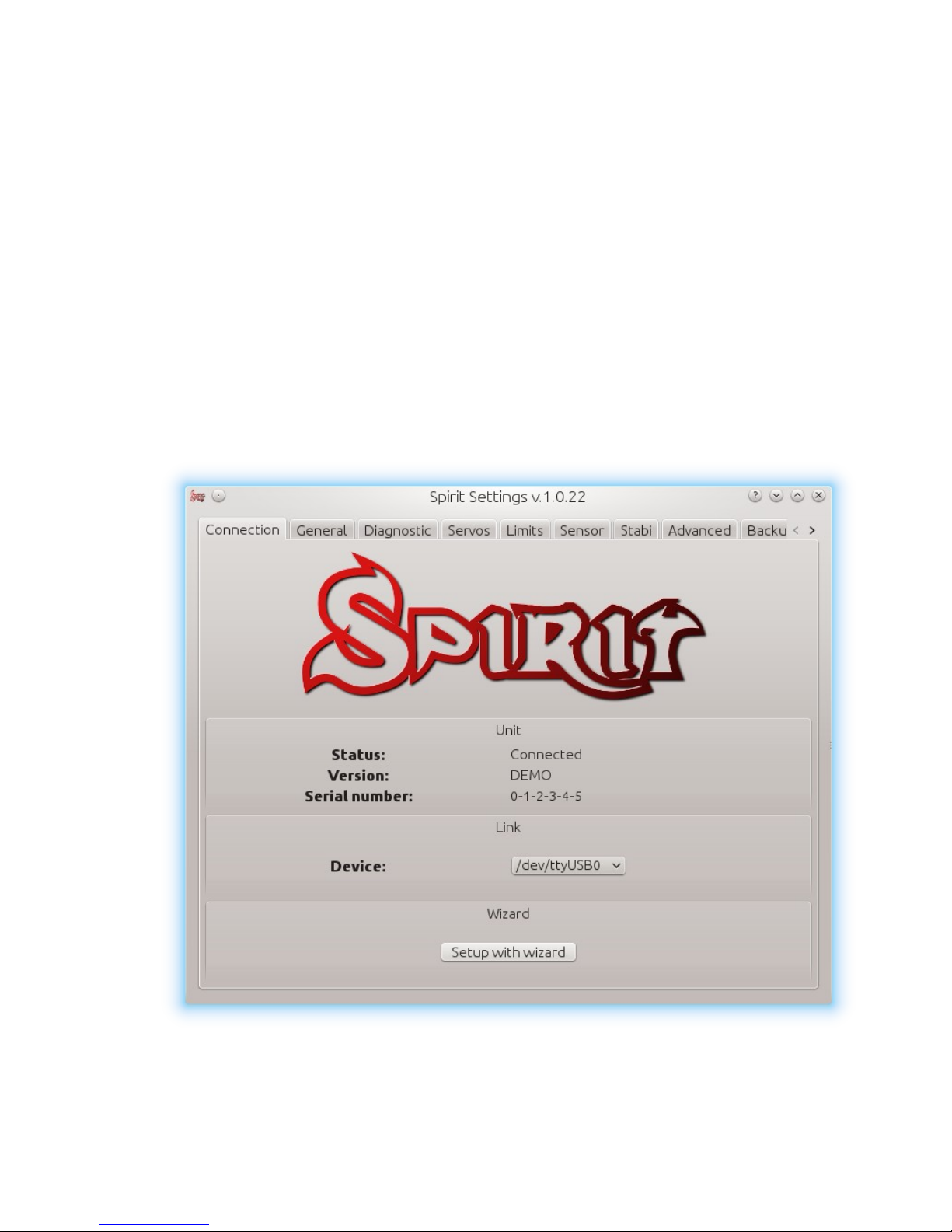
5.5.1 CONNECTION TAB
This tab indicates the current status of connection, informs about the current
version of the firmware, displays the serial number of the unit and allows you
to change communication port. In addition it features a wizard for a first
setup.
We recommend using this wizard, as it guides you through a basic setup in
the easiest way.
14
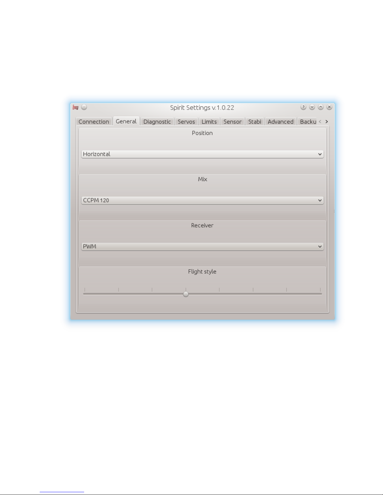
5.5.2. GENERAL
In case you have already set up the unit using the wizard, you can make
additional adjustments. All values here are the same as the ones you have
selected in the wizard and vice versa.
WARNING
Whenever parameters are changed, new value is immediately applied.
Unless settings are saved, after disconnecting the power supply all unsaved
changes are lost, see Backup tab.
15

Position
Select a position in which the unit is attached to the model.
See section 3. Installation.
Mix
Select a swash type mixing of your model. In most cases it is CCPM 120°.
Mixing in the transmitter must be turned off. It is necessary to set H1 type.
Receiver
Select the type of receiver you want to use:
PWM – standard receiver.
PPM - single line connection.
Spektrum DSM2/DSMX - DSM2/DSMX satellite.
Futaba S-BUS - receiver connected via S-BUS.
Flight style
Sets how the model will behave in flight.
This parameter is used to control and adapt behavior according to the
requirements of the pilot.
Lower value means that the model will behave more consistently, more
controlled by the unit.
Higher value means more natural behavioral. The response of stick
movements are more flybar-like.
This parameter does not affect how the model will be stable.
Most pilots prefer default value - 4.
16
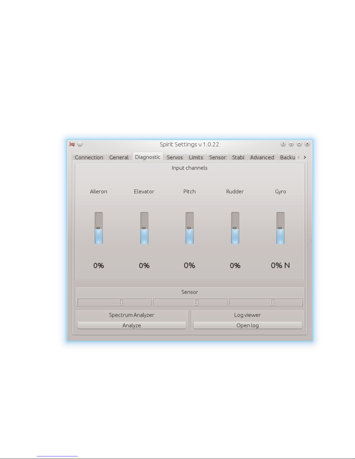
5.5.3 DIAGNOSTIC TAB
If the settings in the previous tab are done it is recommended to do
adjustments in the transmitter at this time.
Each transmitter is different and the center of the channel impulse is never
exactly the same. Even with increasing wear or due to environmental
influences, center of channels can move slightly.
Another factor is the maximum and minimum value of each channel.
Also, there may be greater deviations. Therefore, this software displays these
values. So basically you can unify all transmitters to fulfill requirements.
WARNING
For proper operation of the unit, it is necessary to check values of aileron,
elevator and rudder channels. These three channels must be in neutral stick
deflections at approximately 0%!
17

The unit automatically detects the neutral position during each initialization.
Do not ever use subtrim and trim functions on your transmitter for these three
channels, otherwise it will be considered as a command to move.
So make sure all subtrims and trims are zeroed.
It is also recommended to set the maximum and minimum values.
Test the minimum and maximum deviation for all channels.
If these values are not equal to -100% respectively 100% in the diagnostic tab
it is necessary to compensate this difference.
You will need to set this with dual rate or travel adjust function for both
directions.
Besides channels such as aileron, elevator and rudder, it is necessary to
check pitch channel, too. For this channel it is allowed to use subtrim
function to achieve the center value as precisely as possible
When collective pitch curve is in range between -100 and 100%, the middle
of the stick should be equal to 0%.
After these settings, everything should be configured with regards to the
transmitter.
But if some channel oscillates around the center too much,it may mean
wear of the transmitter, respectively potentiometers. This can be
compensated by increasing stick deadband, described later in Advanced
tab.
If you see that values in channel aileron, elevator, or rudder are marked in
bold, it is recognized as a command to move/rotate the axis.
18

5.5.4 SERVOS TAB
This tab is used for servo configuration, you should be especially careful here.
Type
In this section, set values according to servo specifications for neutral pulse
and frequency.
For analog servo frequency is usually max. 60Hz.
Subtrim (tuning)
Ideally, without rotor head, use cyclic leveler to align servo horns so the
swashplate will be in horizontal position as accurately as possible,
respectively perpendicular to main shaft while servo horns are
perpendicular, too.
19

This is done by ticking item Subtrim (tuning). Then the unit should be switched
into a special mode where the collective position should be neutral all the
time. In addition, stabilization will be turned off.
Servos can be easily adjusted at this time. When all is completed, a
swashplate should be exactly perpendicular to the main shaft and in
addition collective pitch must be at 0°(it is possible to measure the angle
with a pitch gauge with rotor head and blades now).
There is also requirement for servo horns – they should be perpendicular to
servo cases, too.
All servos, i.e., CH1, CH2, CH3 and CH4, are set separately on individual
sliders. CH1 and CH3 are the aileron servos. CH2 controls the elevator and
CH4 controls the rudder.
It is also recommended to set subtrim and mechanics of rudder so that servo
horn is perpendicular to its case and simultaneously rudder pitch is at 0°.
This setting will affect rudder stop performance.
If all is set up, it is necessary to untick the Subtrim (tuning) item to turn off the
special mode.
WARNING
After exiting the special mode stabilization, steering should work again.
Be sure your collective pitch channel is configured correctly in the
transmitter.
That means you should see -100% to 100% in the diagnostic tab.
Double check that 0% in diagnostic tab corresponds with neutral position of
a collective/throttle stick (with linear -100% - 100% collective pitch curve).
Cyclic servos reverse
Choose which servos should be reversed – reversed direction of motion.
While changing the collective pitch all servos should move in same direction.
It is possible to set correct direction of collective travel in the transmitter.
Without reverse - all servos without reversing
CH3 - CH3 servo reversed
CH2 - CH2 servo reversed
CH2 & CH3 – CH2 and CH3 are reversed
20
Table of contents
Popular Toy manuals by other brands

Trix
Trix BR 420 manual

VMI
VMI Micro CAP 232 Assembly instructions

PARKZONE
PARKZONE Ultra-Micro Sukhoi Su-26m BNF instruction manual

Eduard
Eduard Brassin Bf 109E fuselage guns quick start guide

Fisher-Price
Fisher-Price nickelodeon BLAZE AND THE MONSTER MACHINES Blaze to Victory... Assembly instructions

Fisher-Price
Fisher-Price CAR-NIVORES M1803 user manual

Estarmodels
Estarmodels AERONCA C3 instructions

REVELL
REVELL T-34/85 Tank & Siberian Rifleman Assembly manual

Tamiya
Tamiya NEO Fighter Buggy GREEN METALLIC quick start guide

REVELL
REVELL M60A3 & M9 Raumschild Assembly manual

BLOTZ
BLOTZ B20-MD-004 quick start guide

Kid Trax Toys
Kid Trax Toys SRT Viper KT1101WM owner's manual


