Spitznas 2 1362 0010 User manual

Original-Betriebsanleitung, erstellt: 13.07.18
213620010_BA_en_Version_01.doc
Pneumatic
Drill
Type 2 1362 0010
ATEX Tool
Illustration can differ from the original
Translation of the original manual,
compiled: 01.09.21
Techn. Doc. No. 251
Operation
and Maintenance Manual
B.V.Technisch Bureau Duspra Amersfoortseweg 24-14 3951 LB Maarn The Netherlands

Pneumatic Drill
2 1362 0010
Translation of the original manual,
compiled: 01.09.21
213620010_BA_en_Version_01.doc
Page 1 of 30
Directory
Page
Signal Word and Symbol Definition
2
Technical Specification
3
Use
3
Product Description
4
Scope of delivery
4
Identification
5
Installation
6
Startup
7-13
Operation
14-16
Accessoires
17-20
Basic Safety Instructions
21
Employer‘s Obligations
21
Operator‘s Obligations
21
Explanation of Symbols for Protective Equipment and for Accident Prevention
22
Safety Instructions for avoiding Safety Hazards
23-26
Service and Maintenance
27-28
Disassembly –Re-assembly
28
Storage
28
Disposal
28
Environmental Regulations
28
Troubleshooting
29
Warranty and Liability
29
Declaration of Conformity
30
B.V.Technisch Bureau Duspra Amersfoortseweg 24-14 3951 LB Maarn The Netherlands

Pneumatic Drill
2 1362 0010
Translation of the original manual,
compiled: 01.09.21
213620010_BA_en_Version_01.doc
Page 2 of 30
Signal Word and Symbol Definition
The signal words and symbols used in the technical documentation (safety instructions, operating booklet,
etc.) have the following meaning:
WARNING –Read the operation and maintenance manual
It is imperative to familiarize with this operation and maintenance manual and its safety
instructions before starting your SPITZNAS machine. Stick to the operating processes and
avoid accidents due to improper use of the machine.
This symbol has
the following
meaning:
DANGER –Indicates an immediate danger, which causes serious injuries to any person
or even death, if not avoided.
WARNING –Indicates a threatening danger, which can cause serious injuries to any
person or even death, if not avoided.
CAUTION –Indicates a danger or unsafe procedure which can cause injuries to any
person or material damages, if not avoided.
NOTICE –Indicates a potentially dangerous situation which can cause damage to the
product or its surroundings, if not avoided.
WARNING –explosive atmosphere
Air and flammable substances can mix and result in an explosive atmosphere. In areas
exposed to explosion hazards, supplementary instructions and directives apply. Observe
the safety instructions of the employer as well.
WARNING –explosive material
Caution should be exercised when working with explosive material or in its surrounding
area.
PROHIBITION –No naked flame, fire, or ignition source and no smoking
Prevent from fire and explosion hazards, which can be caused by naked flame, open
ignition source or by smoking.
Eating and drinking forbidden –The prohibition sign forbids the consumption of food.
REQUIREMENT –Observe the instruction
Ensure that the operation process is adhered to and avoid accidents and expensive break
down times due to improper use of machines, devices and tools.
By using the mandatory sign you refer to the adherence of operation instructions.
This symbol has
the following
meaning:
NOTICE –Gives recommendations and important hints for handling the product
IMPORTANT –Indicates application advice and other particularly useful information.
REMARK:
In each case the used symbol does not replace the safety text. The text must always be read fully. In some
cases other symbols will be used with the signal words.
WARNING
B.V.Technisch Bureau Duspra Amersfoortseweg 24-14 3951 LB Maarn The Netherlands

Pneumatic Drill
2 1362 0010
Translation of the original manual,
compiled: 01.09.21
213620010_BA_en_Version_01.doc
Page 3 of 30
Technical Specification
Operating pressure
6 bar
Power
1 kW
Free speed step 1, 2, 3, 4
450, 650, 850, 1000 1/min
Rotation direction
reversible
Drill chuck
up to 13 mm
Drilling in steel
max. 30 mm
Thread cutting
max. M12
Air consumption
1.15 m3/min
Air connection
R ¼" female
Weight
3.7 kg
Length with drill chuck
approx. 230 mm
Sound pressure level LpA(1)
84 dB (A)
Sound power level LWA
95 dB (A)
Vibration (2)
< 2.5 m/s²
ATEX Classification
II 2G Ex h IIB T5 Gb
(1) Remark: Measurement acc. to DIN EN ISO 15744
(2) Remark: Measurement acc. to DIN EN ISO 28927-5
Measurement uncertainty K: 3 dB (A)
Measurement uncertainty K: 1.5 m/s2
The performance specifications are guide values only, they depend basically on the application, the
working pressure and the accessories used.
Intended Use
SPITZNAS machines are designed for industrial use only.
Only trained, skilled personnel are allowed to operate the machine. The drill serves for drilling:
Wood, plastic, non-ferrous metal, cast iron, steel and stainless steel
It can be applied for:
Chemical industry / refineries, nuclear industry, body construction and ship building industry, construction.
Improper Use
Any use deviating from the intended use as described is considered to be improper use.
Working without personal protection equipment.
Using the machine in an inadmissible area.
Drilling self-flammable material.
B.V.Technisch Bureau Duspra Amersfoortseweg 24-14 3951 LB Maarn The Netherlands

Pneumatic Drill
2 1362 0010
Translation of the original manual,
compiled: 01.09.21
213620010_BA_en_Version_01.doc
Page 4 of 30
Product Description
Fig. 1
1 Reverse slide
2 Valve trigger
3 Air connection
4 Exhaust
5 Speed regulator
6 Motor housing with pistol grip
7 Drill chuck key
8 Drill chuck
9 Gear housing
10 Second Handle
Scope of Delivery
Check, if the scope of delivery is complete:
1 Pneumatic Drill, 1 Operation and Maintenance Manual, 1 Carrying case and accessories, if applicable
4
6
2
3
5
7
8
9
1
10
B.V.Technisch Bureau Duspra Amersfoortseweg 24-14 3951 LB Maarn The Netherlands

Pneumatic Drill
2 1362 0010
Translation of the original manual,
compiled: 01.09.21
213620010_BA_en_Version_01.doc
Page 5 of 30
Identification
Type sign Explanation of ATEX Identification
CE specification
Specification
acc. to 2014/34/EU
Address
Technical specification
ATEX Identification
Company name and Logo
Serial number (1. and 2. figure refer to the
year of manufacture/ following figures refer
to the series)
Type description
Machine group II
Explosive atmospheres
e. g. Industry
Category 2
Very high level of safety
High level of safety
Normal level of safety
1
2
3
Ex-Atmosphere G
Gas, vapor and mist
Marking according to
standard - Ex-Symbol
Ignition protection category h
Code letter h for all
non-electrical equipment
Explosion group IIB
e.g. Methane, Propane
e.g. Ethylene, Town gas
e.g. Hydrogene, Acethylene
IIA
IIB
IIC
Temperature class T
Surface limit temperature
450°C
300°C
200°C
135°C
100°C
85°C
T1
T2
T3
T4
T5
T6
Equipment Protection Level
Group II EPL Gb
Category 2 (usable in category 3 as well) explosion group IIB usable in explosion group IIA as well.
B.V.Technisch Bureau Duspra Amersfoortseweg 24-14 3951 LB Maarn The Netherlands

Pneumatic Drill
2 1362 0010
Translation of the original manual,
compiled: 01.09.21
213620010_BA_en_Version_01.doc
Page 6 of 30
Installation
Requirements to the air supply
The pneumatic drill works optimally at an operating pressure of 6 bar, measured at the air inlet. The distance
from the air supply to the machine has to be adjusted to the application conditions on site.
We recommend installing an oiler or a maintenance unit upstream the machine for compressed air
preparation. Use acid and resin-free lubricating oil, like SAE 5W - SAE 10W.
Attention! Do not use viscous oil.
Use an antifreeze lubricant during winter time or when the compressed air is very moist, e.g.:
“Kilfrost”
or “Kompranol N74”.
The supplied compressed air has to be free of:
Foreign particles,
humidity.
Pay attention that all hoses:
Have a cross section being large enough,
do not have any restrictions or kinks,
are designed for a minimum operating pressure of 6 bar,
are replaced regularly at preventative maintenance,
have an oil resistant inner surface and an abrasion-resistant outer surface,
are proved and specified to be non-conductive when being used next to electric conductors.
Always use hoses, lubricating oil and antifreeze lubricants, which meet the local safety requirements for use
in areas exposed to explosion hazards.
Connecting the air supply to the pneumatic drill
Remove the locking cap from the air connection 3. Connect the pneumatic hose (not contained in the scope
of delivery).
Exhaust Air inlet
Fig.2
3
4
B.V.Technisch Bureau Duspra Amersfoortseweg 24-14 3951 LB Maarn The Netherlands

Pneumatic Drill
2 1362 0010
Translation of the original manual,
compiled: 01.09.21
213620010_BA_en_Version_01.doc
Page 7 of 30
Startup
Assembly of the handle
Fix the second handle item 10 at the side (see fig. 3 and 4).
Fig. 3
Fig.4
Turn
10
B.V.Technisch Bureau Duspra Amersfoortseweg 24-14 3951 LB Maarn The Netherlands

Pneumatic Drill
2 1362 0010
Translation of the original manual,
compiled: 01.09.21
213620010_BA_en_Version_01.doc
Page 8 of 30
Connection of the air supply
Sample application: Quick-coupling for the air connection
Screw-in nipple (not contained in the scope of delivery) (see fig. 5 and 6).
Fig. 5
Fig.6
B.V.Technisch Bureau Duspra Amersfoortseweg 24-14 3951 LB Maarn The Netherlands
Pneumatic Drill
2 1362 0010
Translation of the original manual,
compiled: 01.09.21
213620010_BA_en_Version_01.doc
Page 9 of 30
Blow out the pneumatic hose before connecting the machine.
Never connect a pneumatic hose being under pressure (see safety instructions for prevention of hazards
caused by compressed air).
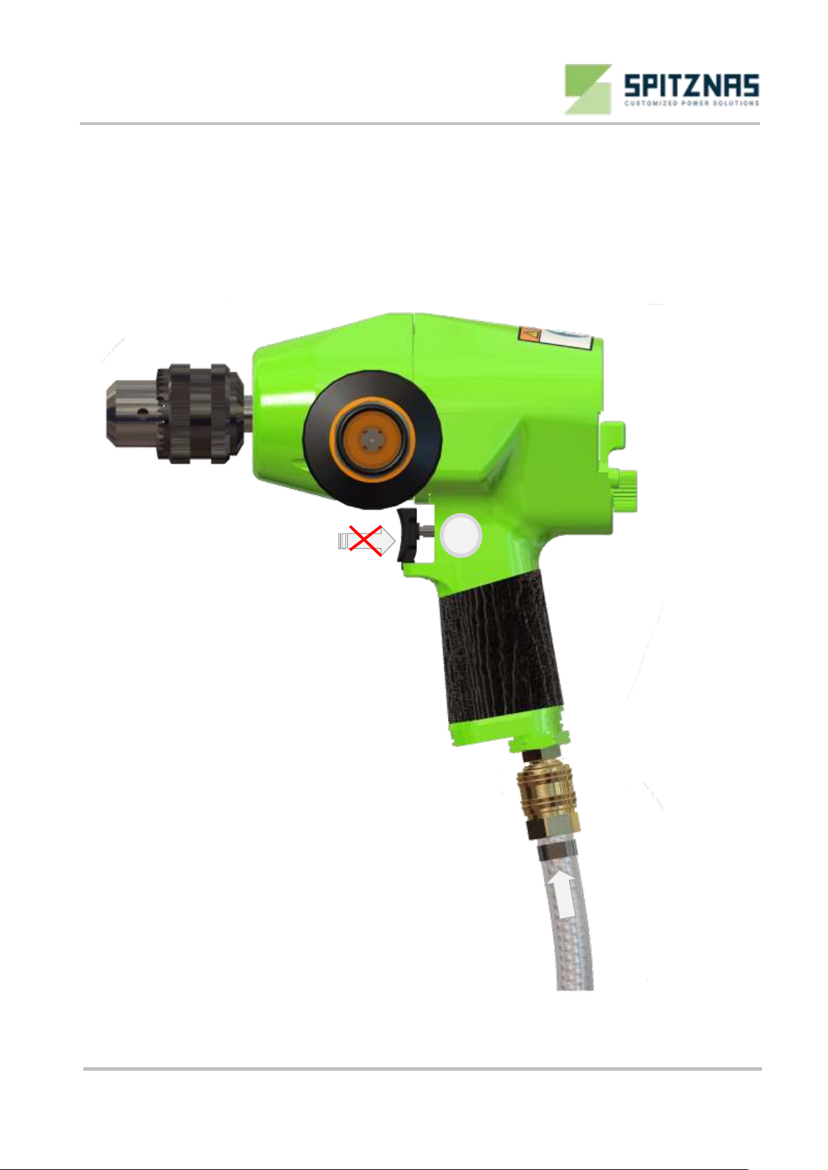
When connecting the machine, pay attention that the valve trigger 2 (see fig.7) is not actuated.
First connect the machine and then connect the compressed air supply.
Make a test run.
Fig. 7
2
B.V.Technisch Bureau Duspra Amersfoortseweg 24-14 3951 LB Maarn The Netherlands

Pneumatic Drill
2 1362 0010
Translation of the original manual,
compiled: 01.09.21
213620010_BA_en_Version_01.doc
Page 10 of 30
Mounting the drill bit
When mounting the drill bit, ensure that the pneumatic hose ist not connected, respectively that the
pneumatic supply is deactivated. Depressurize the pneumatic drill and disconnect the pneumatic hose
(see fig. 8).
Fig. 8
B.V.Technisch Bureau Duspra Amersfoortseweg 24-14 3951 LB Maarn The Netherlands
Pneumatic Drill
2 1362 0010
Translation of the original manual,
compiled: 01.09.21
213620010_BA_en_Version_01.doc
Page 11 of 30
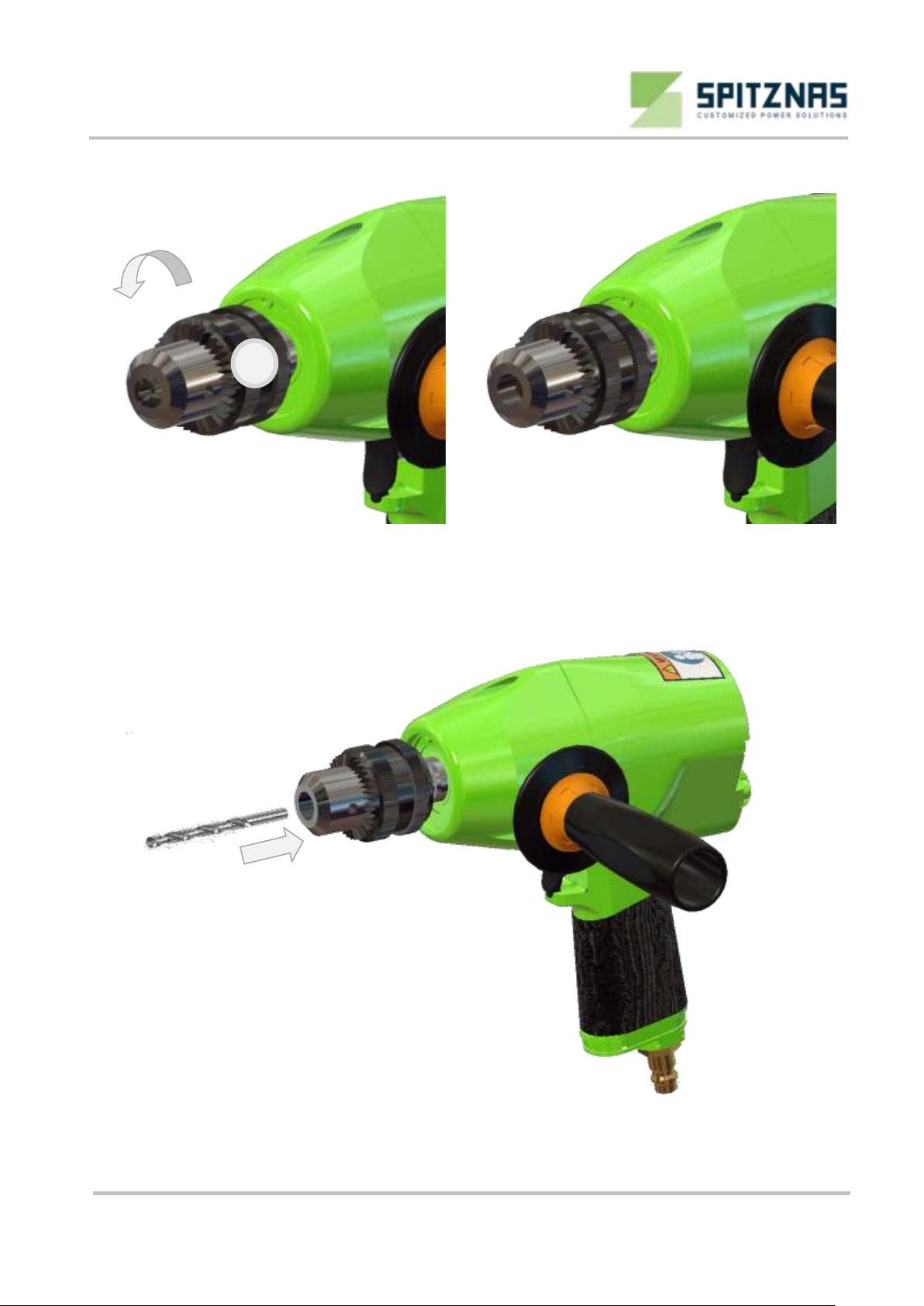
Open the drill chuck item 8 by turning until the drill bit can be mounted. (see fig. 9 and 10).
Fig. 9 Fig. 10
Mount the drill bit (see fig.11).
Fig. 11
Turn to open
8
B.V.Technisch Bureau Duspra Amersfoortseweg 24-14 3951 LB Maarn The Netherlands
Pneumatic Drill
2 1362 0010
Translation of the original manual,
compiled: 01.09.21
213620010_BA_en_Version_01.doc
Page 12 of 30
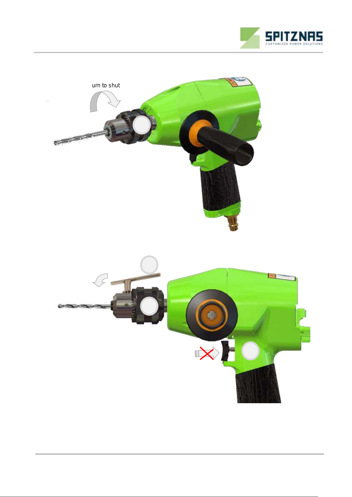
Turn the drill chuck item 8 against the opening direction (see fig.12).
Fig. 12
Put the drill chuck key item 7 (see fig. 13) in the corresponding drillings of the drill chuck item 8 and tighten
the drill bit evenly.
Tighten
Fig. 13
When connecting the machine, ensure that the valve trigger item 2 (see fig. 13) is not actuated.
Never connect a pressurized pneumatic hose (see safety instructions for prevention of hazards caused by
pneumatic). First connect the machine and then the pneumatic supply.
Turn to shut
2
8
7
8
B.V.Technisch Bureau Duspra Amersfoortseweg 24-14 3951 LB Maarn The Netherlands
Pneumatic Drill
2 1362 0010
Translation of the original manual,
compiled: 01.09.21
213620010_BA_en_Version_01.doc
Page 13 of 30
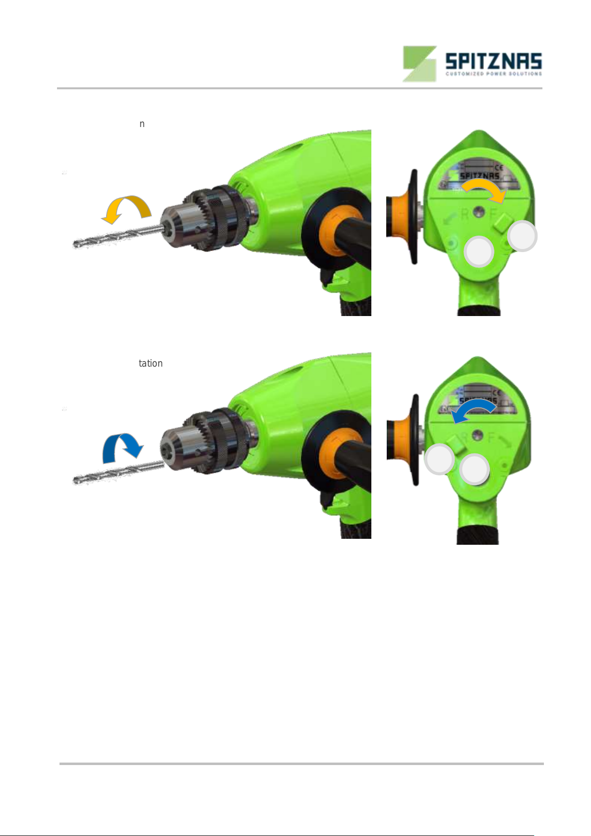
Adjusting the rotation direction
Clockwise rotation
Fig. 14 F„Forward“ for clockwise
rotation
Anti-clockwise rotation
Fig. 15 R „Reverse“ for anti-clockwise
rotation.
Prior to starting work
Check:
That the drill bit is properly tightened in the drill chuck,
That the pneumatic hose is properly connected,
That the rotation direction is adjusted with the reverse slide item 1 and the speed stage is correctly
adjusted with the speed regulator item 5 (see fig. 14 and 15).
Start the machine by actuating the valve trigger item 2 and start operating. The drill bit has to be cooled with
water in order to avoid sparks.
After finishing the work
Release valve trigger.
Shut the pneumatic supply, disconnect the pneumatic hose.
Dismount the drill bit, if necessary.
1
1
5
5
B.V.Technisch Bureau Duspra Amersfoortseweg 24-14 3951 LB Maarn The Netherlands

Pneumatic Drill
2 1362 0010
Translation of the original manual,
compiled: 01.09.21
213620010_BA_en_Version_01.doc
Page 14 of 30
Operation
Replacing the drill bit
Shut the pneumatic supply and secure against unintentional starting. Depressurize the pneumatic drill and
disconnect the pneumatic hose. Wear protective gloves when replacing the drill bit, as the drill bit and the
drill chuck can strongly heat up during longer operation. Put the drill chuck key item 7 (see fig. 16) in the
corresponding drillings of the drill chuck item 8 and undo the drill bit.
Undo
Fig. 16
Open the drill chuck item 8 by turning and take the drill bit out of the drill chuck (see fig. 17 and 18).
Fig. 17 Fig. 18
Mount the drill bit (see fig. 19).
Fig. 19
Turn to open
8
2
7
8
B.V.Technisch Bureau Duspra Amersfoortseweg 24-14 3951 LB Maarn The Netherlands

Pneumatic Drill
2 1362 0010
Translation of the original manual,
compiled: 01.09.21
213620010_BA_en_Version_01.doc
Page 15 of 30
Turn the drill chuck item 8 against the opening direction (see fig. 20).
Fig. 20
Put the drill chuck key item 7 (see fig. 21) in the corresponding drillings of the drill chuck key item 8 and
tighten the drill bit evenly.
Tighten
Fig. 21
Actuate the pneumatic supply.
Adjust the rotation direction (see „Adjusting the rotation direction“ on page 13) and start drilling.
Turn to shut
2
8
7
8
B.V.Technisch Bureau Duspra Amersfoortseweg 24-14 3951 LB Maarn The Netherlands

Pneumatic Drill
2 1362 0010
Translation of the original manual,
compiled: 01.09.21
213620010_BA_en_Version_01.doc
Page 16 of 30
Second handle
The second handle item 10 can be mounted at two positions.
Undo the second handle item 10 (see fig. 22 and 23) .
Fig. 22 Fig. 23
Mount the second handle item 9 at the opposite side (see fig. 24 and 25).
Fig. 24 Fig. 25
10
10
B.V.Technisch Bureau Duspra Amersfoortseweg 24-14 3951 LB Maarn The Netherlands

Pneumatic Drill
2 1362 0010
Translation of the original manual,
compiled: 01.09.21
213620010_BA_en_Version_01.doc
Page 17 of 30
Accessories
Mount the quick-release chuck
SPITZNAS part no.: 9 2902 0040
Shut the pneumatic supply and disconnect the pneumatic hose from the pneumatic drill. Wear protective
gloves when replacing the drill chuck to avoid injuries.
Open the drill chuck item 8 by turning. (see fig. 26).
Fig. 26
Put the hexagon screw driver SW 5 through the drill chuck item 8 on the socket head
screw (see fig. 27 and 28).
Fig. 27 Fig. 28
Turn the hexagon screw driver SW 5 until the drill chuck item 8 becomes loose and pull it from the shaft
(see fig. 29 and 30) .
Fig. 29 Fig. 30
Turn to open
8
Undo by turning
8
8
B.V.Technisch Bureau Duspra Amersfoortseweg 24-14 3951 LB Maarn The Netherlands

Pneumatic Drill
2 1362 0010
Translation of the original manual,
compiled: 01.09.21
213620010_BA_en_Version_01.doc
Page 18 of 30
Tighten the socket head screw and put the quick-release chuck onto the shaft (see fig. 31 and 32).
Fig. 31 Fig. 32
Disassembling the quick-release chuck
SPITZNAS part no. 9 2902 0040
Put a wedge with the pneumatic drill on a support. Put a second wedge on the top and drive the quick-
release chuck off the shaft by slightly hammering. (see fig 33 to 36).
Fig. 33 Fig. 34
Fig. 35 Fig. 36
B.V.Technisch Bureau Duspra Amersfoortseweg 24-14 3951 LB Maarn The Netherlands

Pneumatic Drill
2 1362 0010
Translation of the original manual,
compiled: 01.09.21
213620010_BA_en_Version_01.doc
Page 19 of 30
Mounting the exhaust connection
SPITZNAS part no.: 6 1034 9100
Fig. 37
A Exhaust connection with hose nozzle
B Hose nozzle for air supply
A
B
B.V.Technisch Bureau Duspra Amersfoortseweg 24-14 3951 LB Maarn The Netherlands
Table of contents
Other Spitznas Drill manuals


